1. Introduction
The first electric vehicles were built in the 19th century, but due to technical limitations, they lost their place to combustion vehicles, which pushed them out of the market almost completely for nearly 150 years. Hope for the development of electromobility was given by the work of Henney Kilowatt, who in the late 1950s produced the first electric car based on transistor technology. Although this project was not successful and the production of these cars was discontinued after two years, the same use of transistors to build electric drives laid the foundations for the development of the propulsion systems used in electric vehicles [
1].
In addition to the development of technology, the factors that are conducive to the development and spread of electromobility are the finite stocks of mineral resources, the climate policy of European Union countries, and the growing awareness of people of their impact on climate change. Electric vehicles are seen as an opportunity to provide environmentally friendly means of transport that do not emit greenhouse gases into the atmosphere or cause smog [
2]. From an energy policy point of view, electromobility offers the opportunity to achieve the objectives of decarbonization and decentralization of electricity sources [
3,
4] and can be used in the future to integrate renewable energy sources into the electricity grid by using electric vehicles as mobile electricity storage facilities [
5]. By 2040, it is predicted that the number of such vehicles will be around 500 million [
6], which will directly contribute to the creation of an extensive infrastructure of charging points for electric cars [
7,
8,
9]. For distribution network operators, this means a dynamic increase in the number of converter systems supplying and releasing electricity to the networks owned by them [
10,
11]. At present, there is a lack of measurement data that can clearly show how electric vehicle charging systems will affect the quality of electricity, and the results of simulation studies presented in various research studies are often contradictory—some of them present an almost catastrophic impact of electric vehicle chargers on the distribution network, while others prove that electromobility (apart from the increase in electricity demand) will remain indifferent to this network.
Considering the above issues, the authors of the present study conducted their own simulation studies and based on the results of the conducted measurements, they presented their own approach on how to conduct these studies. The present study aimed to demonstrate that the appropriate development of models of electric vehicle charging systems enables to assess the impact of these systems on electricity quality by using computer simulations [
12,
13]. The authors of the present study also wish to draw attention to the risks and opportunities that will arise from the installation of electric vehicle chargers in power supply networks and present recommendations that can be used to develop appropriate technical standards and introduce changes to the instructions for the operation and use of distribution networks.
2. Related Work
As mentioned above, many analyses and simulations showing the potential impact of electromobility on electricity quality have been published. The results of these analyses are often divergent, which may result from different assumptions for building simulation models, different number and type of chargers to be modeled, and the parameters of the electricity grid adopted for the simulation [
6,
7,
8,
9,
10,
11,
12,
13,
14,
15,
16,
17,
18,
19].
An example of simulation tests, whose purpose was to determine whether electric vehicle chargers will deteriorate the quality parameters of electric energy, is the tests described in [
17,
19,
20]. Although assumptions and approaches to the research itself were quite similar, different results were obtained.
In [
17], a 13-node low-voltage network supplied unilaterally from the transformer station was modeled. The network was 80% loaded. A total of 65 charging points for electric vehicles of 3.7 kW each were connected to this network; the charging point load was modeled on the basis of the results of other tests from which the distribution of higher harmonics generated by electric vehicle chargers was taken. For these assumptions, three scenarios for the operation of this network were developed depending on the number of electric vehicles charging (share of charging points in the total load of the network: 5%, 15%, and 23%). The worst-case scenario had a 23% share of charging points and a 90% load on the grid. The total harmonic distortion of voltage (THD
U) value did not exceed 1.2%. The total harmonic distortion of current (THD
I) value was also low—just over 3%. Therefore, no negative impact on the quality of electricity was observed, even though 23% of the network load at a given time was made up of converter systems.
For comparison, [
19] also modeled a low-voltage network powered from one transformer station and, as before, presented three scenarios of charging the network by electric vehicle charging points, which was also based on previous publications and models of charging systems built as a combination of passive elements and current harmonic sources. Importantly, these simulations address the issue of coordinated and uncoordinated charging of electric vehicles. Uncoordinated charging is assumed to occur when electric car users have charged their cars according to their needs without paying attention to the current load on the grid, e.g., during the evening peak hours. The idea of coordinated charging, on the other hand, was that electric car users consciously used the time outside the peak hours of the mains load to smoothen the daily load curve. The main conclusion of this study, from the point of view of the impact of electromobility on electricity quality, was to prove that saturation with converter systems such as chargers would have negative effects on the grid. The THD
U was less than 8% only for the two cases of coordinated charging with the lowest proportion of charging points in the total grid load. For all other situations, the assumptions of the standard [
21] were not met. It was observed that power take-offs can be as high as 15% and voltage drops can be as high as 20%.
The obtained results and conclusions in [
19] are extremely different from those presented in [
17] despite similar initial assumptions. An interesting approach to the study of the impact of charging systems on electricity quality was presented in [
22]. It presents a model of a real low-voltage grid near Salzburg, to which electric vehicle charging points are connected. The simulations were performed for two scenarios: controlled and uncontrolled charging. For controlled charging, each charger checked the load on the mains and adapted the charging power to it. If the mains were not overloaded, the cars were charged at full power. In contrast, uncontrolled charging, as in [
19], consisted simply of connecting the car to the mains charge at the moment convenient for the user, without checking whether the mains were overloaded. The results obtained indicated that for uncontrolled charging, voltage drops greater than the permitted ones may occur and the cables feeding the charger may be overloaded. These tests considered the state of charge (SoC) of the battery of the electric vehicle. It has been noted that the most unfavorable situation may occur when electric vehicles are charging at the same time, e.g., during the morning or evening peak hours.
A very interesting approach to verify the potential impact of electromobility on the quality of electricity was adopted in [
20]. Similar to earlier simulations, a low-voltage network powered from one transformer station was used for testing. It was assumed that 108 single-phase loads are supplied from this network, and various scenarios of operation of this network were developed depending on the number of electric vehicle charging systems and photovoltaic installations. To assess whether there is a seasonal difference in the impact of electric vehicle charging on the quality of electricity, the study was conducted for selected days during the summer and winter. Two charging scenarios were also assumed: coordinated and uncoordinated charging.
For uncoordinated charging at 30% and 70% of the mains load of electric vehicle charging systems, it has been proven that the impact of charging electric vehicles is highly dependent on the base load of the network under consideration, as for both cases, the exceeding of the allowable current load of the power cable was recorded. According to the results obtained, the most critical situations occur during high mains load in winter and summer when 70% of the mains is saturated by charging systems. As reported in previous publications, uncoordinated charging has increased the peak of evening electricity demand, and when electric cars are charged in a planned manner (coordinated charging), the daily load curve becomes flattened (peak shaving) and power losses decrease. A very interesting conclusion was to draw attention to the possible occurrence of voltage asymmetry for a large number of single-phase chargers installed in the network, because in real power systems, it is not possible to control to which phase a charger will be connected.
None of the above publications reported simulation models built on the basis of measurements carried out, and models developed on the basis of other studies were used. It has not been analyzed how charging systems of electric vehicles due to their structure and power can affect the quality of electricity.
The authors of the present study have developed their own models of electric vehicle chargers on the basis of measurements carried out, technical standards, data provided by equipment manufacturers, and analysis of the available literature. To develop a model of the power supply network, the parameters of the actual distribution network were used. The authors aimed to develop as faithful simulation models as possible, which will allow to answer the question of whether and for which conditions electric vehicle charging systems will have a negative impact on electricity quality.
3. Methodology
3.1. Modeling of Charging Stations
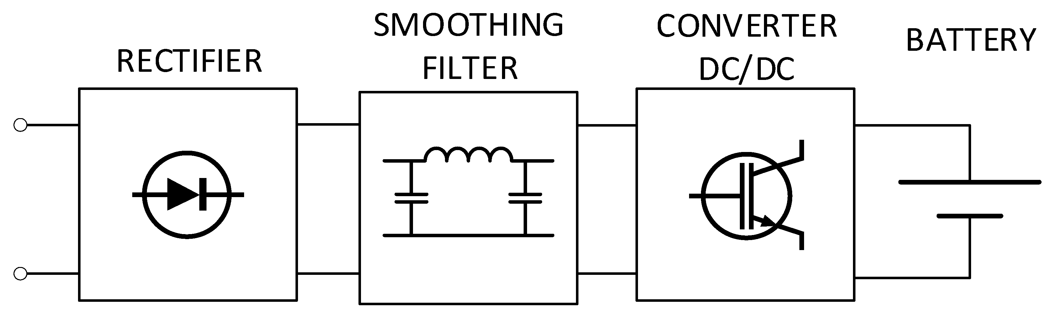
Simplifying the description of the charger’s operation, it can be stated that the task of the charger is to straighten and adjust the voltage to a level that ensures safe charging of the batteries inside the vehicle. Each charger consists of two basic parts: a charger and a DC/DC converter [
23]. The charger converts the alternating current from the distribution network into a direct current, which can be used to charge the battery in the electric car. The DC/DC converter, on the other hand, is responsible for adjusting the DC voltage to the current SoC of the battery and controls the charging process.
There are chargers with a one-way grid-to-vehicle (G2V) energy flow: they are powered from the mains, and their design does not allow energy to be fed back into the mains, where the two halves straightening is provided by a diode bridge system [
24]. The systems that enable bidirectional flow of electricity between the mains and the charger are becoming increasingly popular: these include V2G charging systems, in which two-headed rectification is carried out by a transistor–diode system [
25].
For the purpose of this work, models of both unidirectional and bidirectional chargers were developed.
Figure 1 shows a simplified block diagram of an electric vehicle charger.
3.1.1. G2V Charger Model
The selection of individual elements of the G2V charger was preceded by a detailed analysis of the available literature and an analysis of the measurements carried out, during which the characteristics of the current and voltage course were excluded and the distribution of higher harmonics of current and voltage was recorded, as described in [
26,
27,
28].
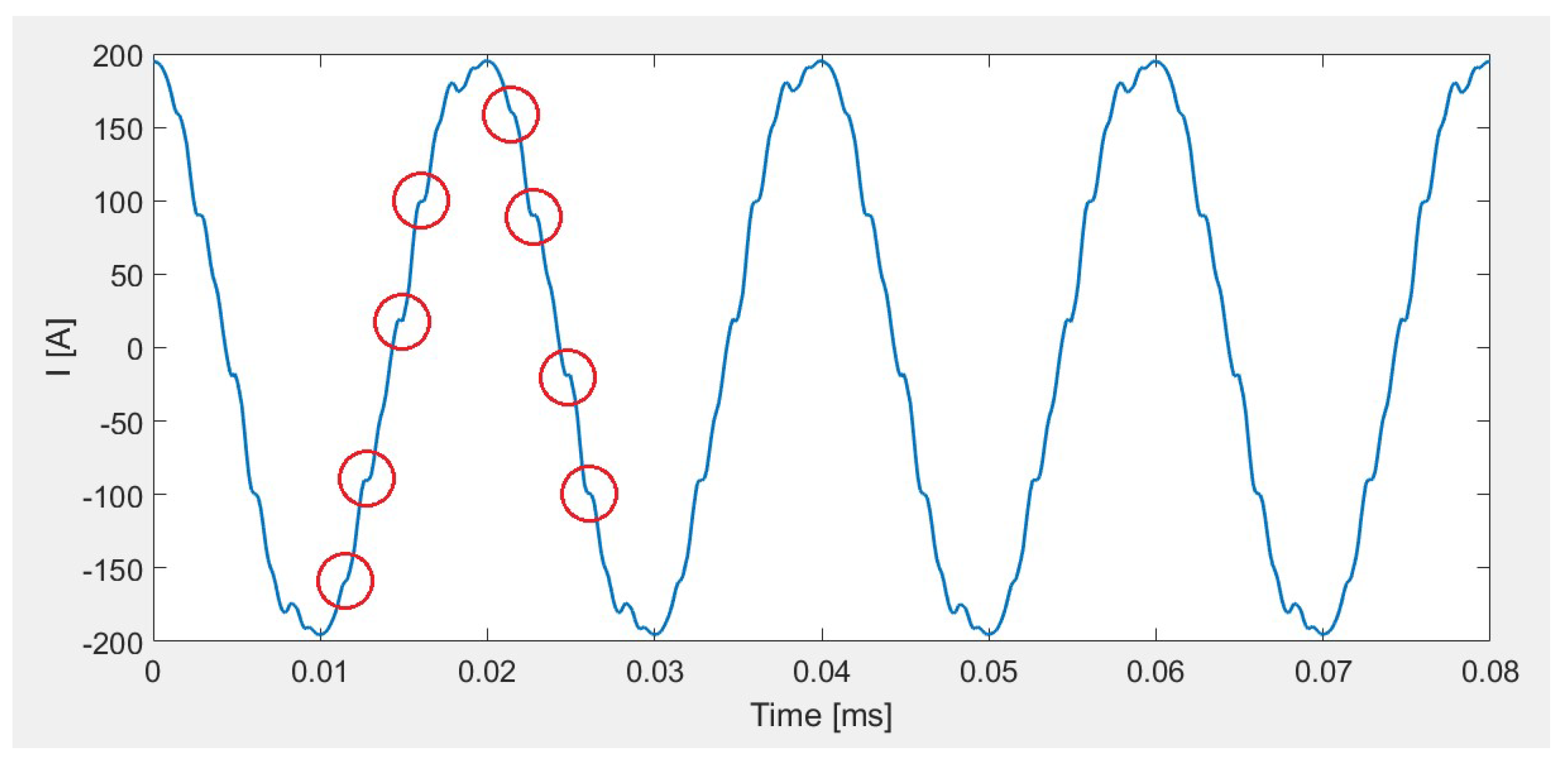
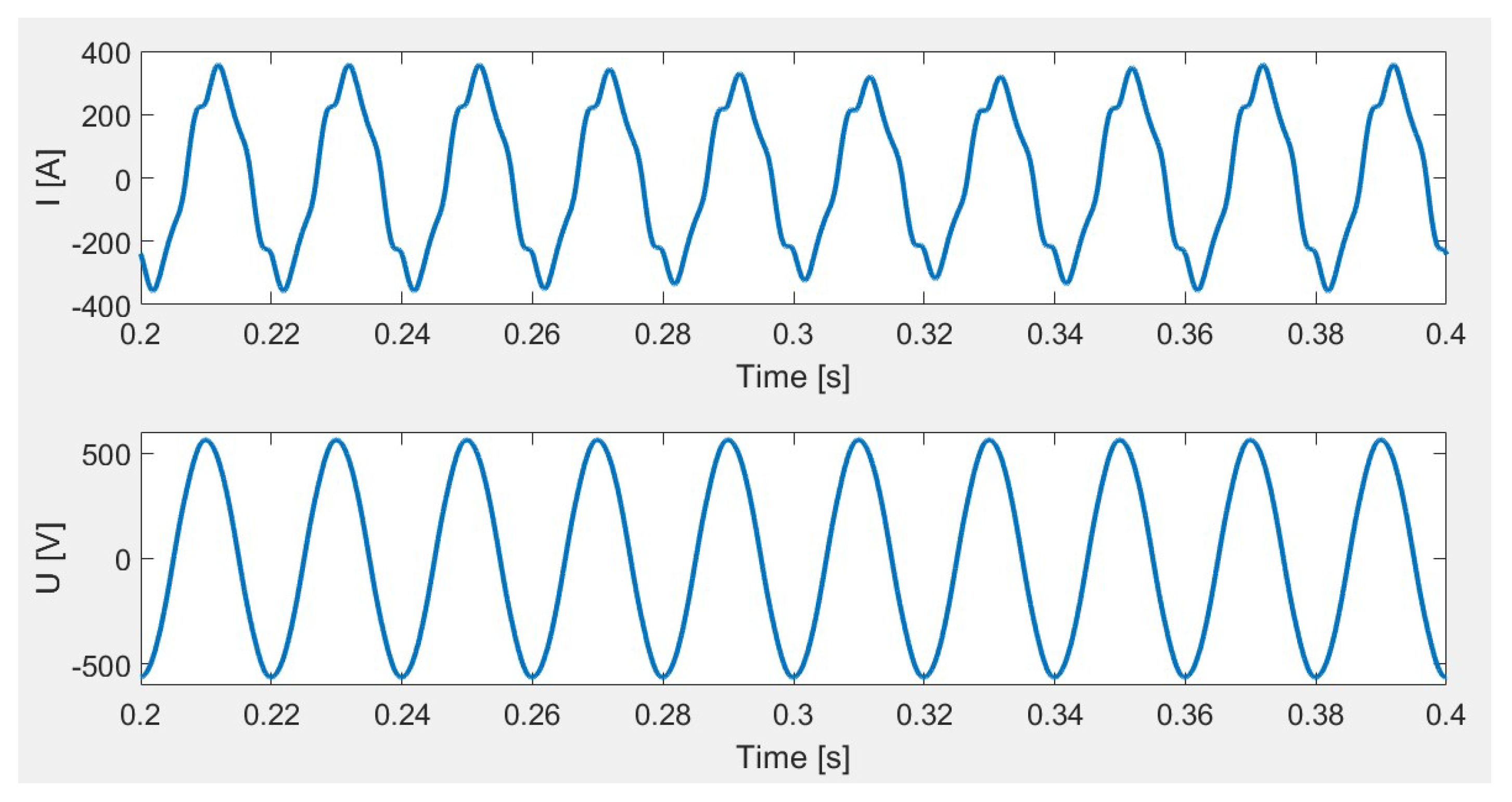
The type of rectifier was chosen on the basis of comparison of the simulated current with the measurements registered with the system for which the type of rectifier used was known (
Figure 2).
Current shown in
Figure 2 exhibits characteristic “stairs” (marked with red circles), betraying the use of an uncontrolled 12-pulse rectifier as an input system [
29]. To obtain more data necessary for investigation, the higher harmonic spectra were recorded during the measurements and compared with the theoretical distribution of higher harmonics assumed for different types of rectifiers.
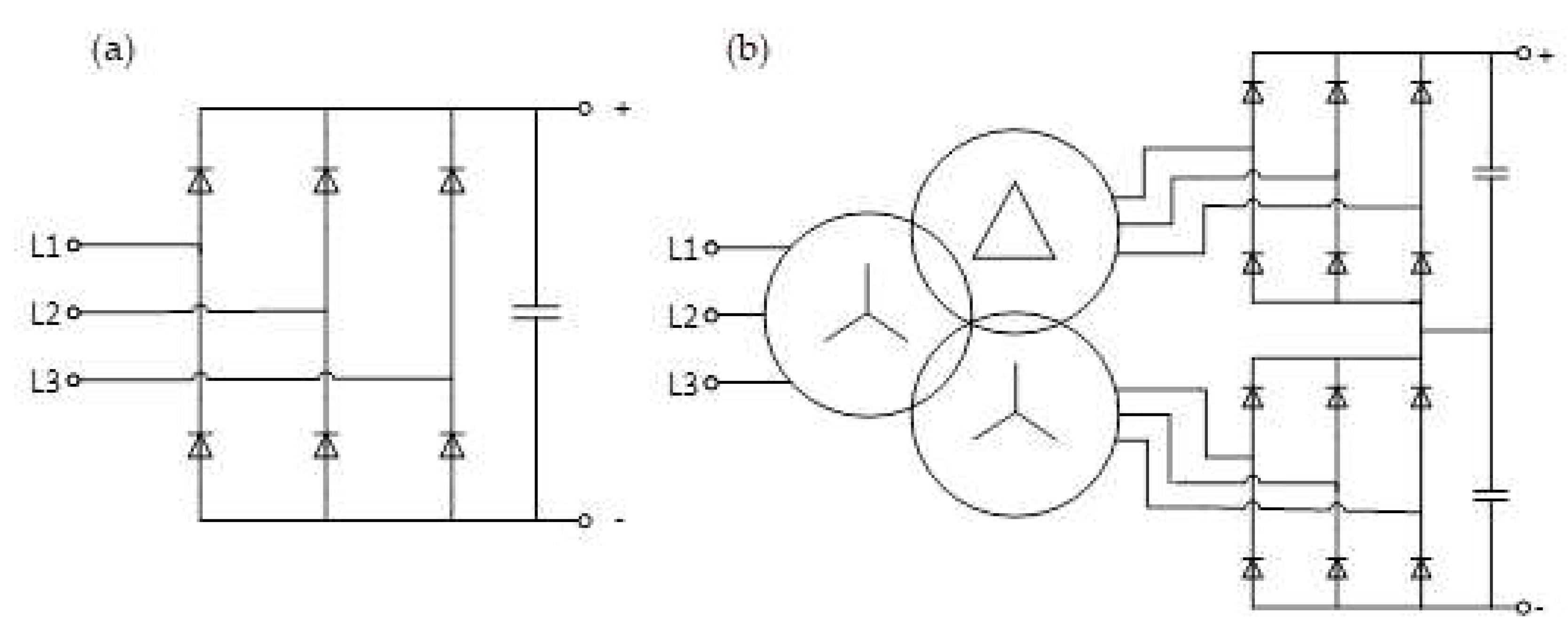
Using the presented reasoning, a 200 kW charger model was developed that included a 12-pulse rectifier. In models of 22 and 40 kW chargers, 6-pulse rectifiers were used—they are justified by the lower rated power. The rectifier models are shown in
Figure 3.
For damping of higher harmonics in high-power systems (above 10 kW) with converter rectifiers, LC filters in T-system, Γ-system, or electromagnetic interference filters (EMI filters) [
30] are most commonly used. The use of these filters has a positive effect on the current and voltage supply—their characteristics become smoother, which translates into a reduction in the potential negative impact of charging systems on the quality of electricity. If the filters are used well, the type of charger, the value of the charger supply voltage, and the maximum value of the load current should be considered [
31].
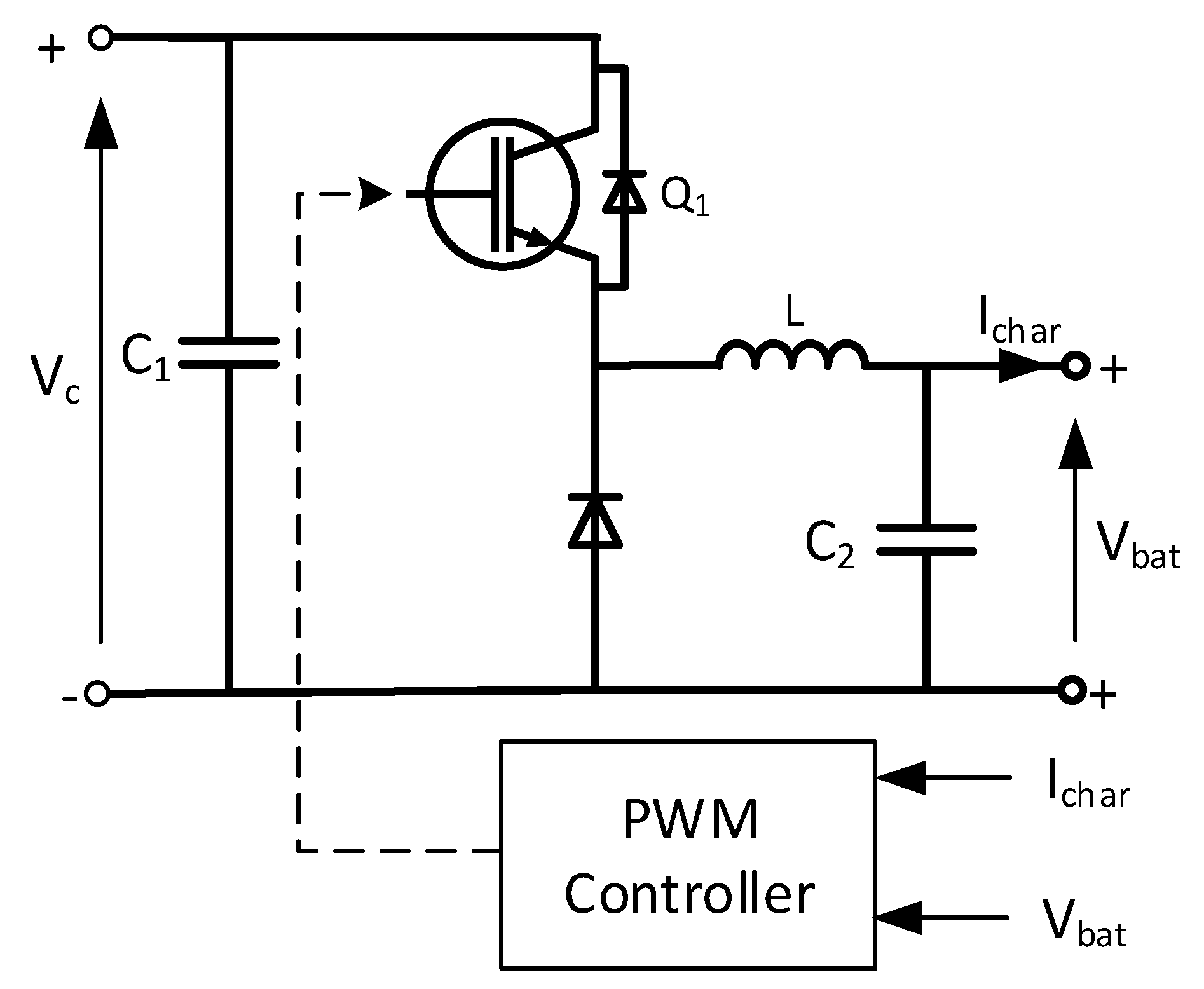
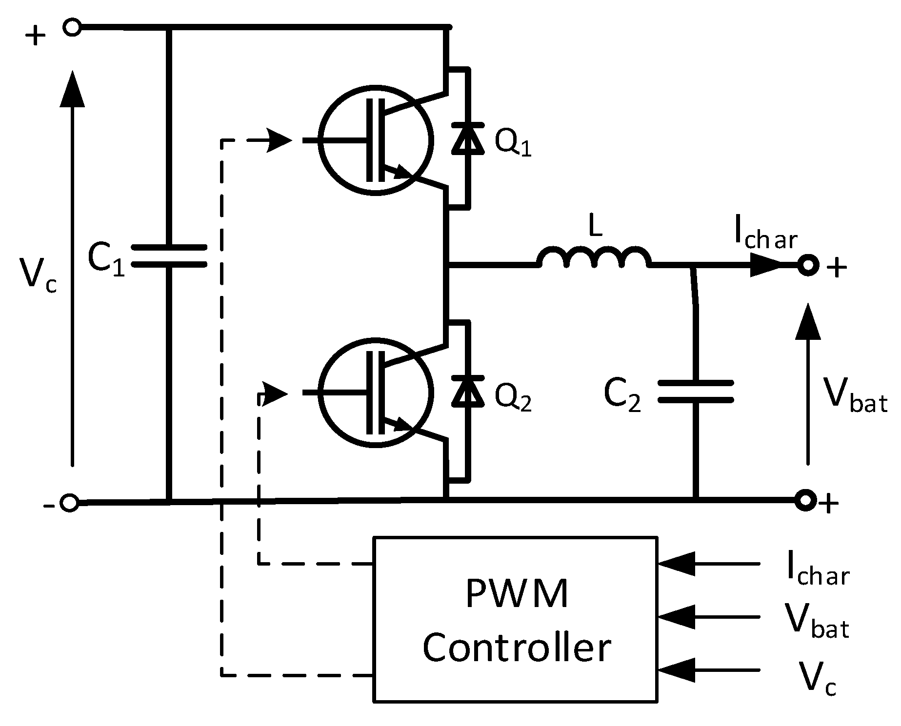
A DC/DC converter built with one of the available topologies can be used, e.g., full-bridge or half-bridge transformer and transformer-less buck, boost, or buck–boost type [
32]. In all topologies, the battery charging current is regulated by changing the transistor duty cycle. This frequency is very high in relation to the distribution network frequency and ranges from tens of kHz to several MHz. The developed models of electric vehicle chargers use a DC/DC converter in buck topology. A diagram of this converter model is shown in
Figure 4.
This topology was chosen mainly because of its numerous applications in simulations of electric vehicle charging systems [
32,
33,
34]. The popularity of this solution is mainly due to its simplicity and the associated low cost of converter construction. Proper operation of the DC/DC converter model is ensured by properly selected elements, which was done in accordance with the guidelines of the Richtek company [
35].
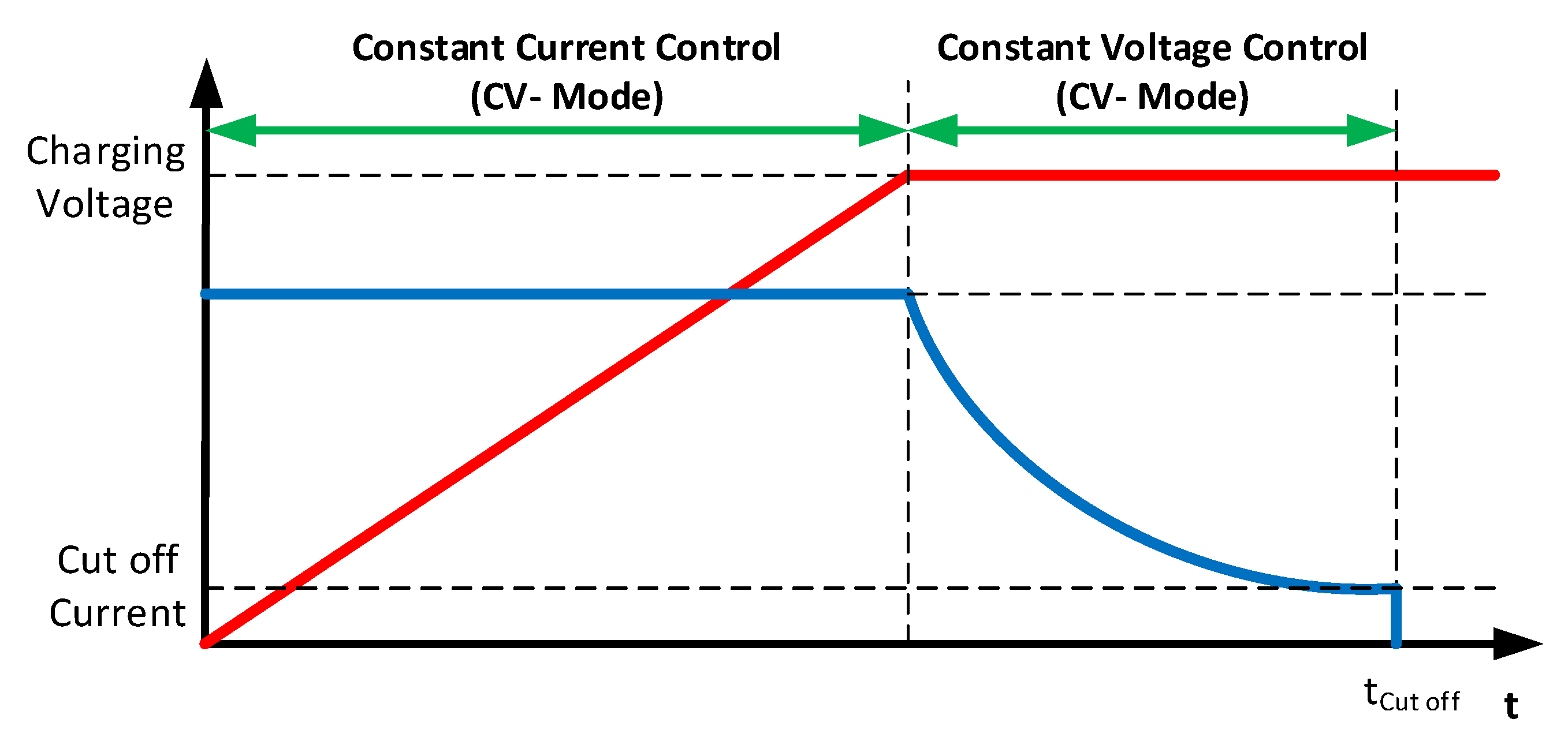
To control the converter, an automatic pulse-width modulation (PWM) control system model was developed which generates a rectangular signal to control the switching on and off of the transistor. This system ensures the best charging conditions by controlling the duty cycle of the transistor control signal. The maximum charging current and the maximum charging voltage are given as reference values. When the charging current value is lower than the present value, the system will increase the PWM duty cycle until the desired value—the maximum charging current—is reached. If the charging current is too high, the duty cycle is reduced.
This process is maintained until the battery voltage reaches a preset value—the maximum charging voltage. At this point, the system switches to the charging voltage stabilization mode. In addition, the automatic control system monitors the battery charge status (SoC). The process described above is performed by the most commonly used battery charging algorithm, constant current mode (CC-Mode)/constant voltage mode (CV-Mode) [
36,
37], which is shown in
Figure 5.
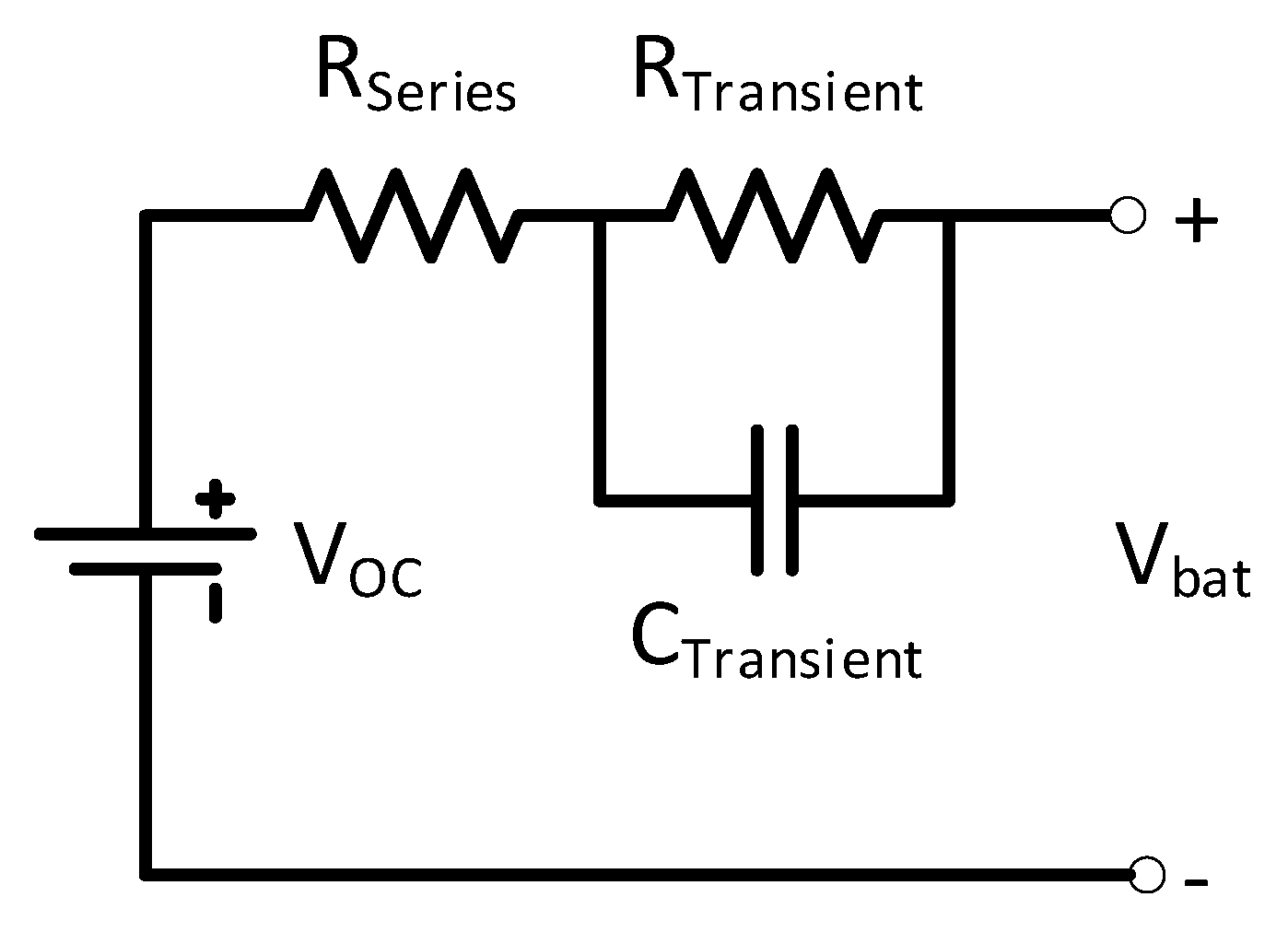
By using the approach presented in [
32,
33,
34], the model of the battery was developed on the basis of Thevenin’s battery replacement scheme (
Figure 6).
3.1.2. V2G Charger Model
The previously developed buck-type inverter model was modified to model a charger that allows the bidirectional flow of electricity between the mains and the battery in the electric vehicle.
An important property that enables the charger in the V2G mode is that the DC voltage is higher than the maximum value of the line voltage supplying the charger. Hence, a buck–boost topology converter is used, which enables operation in a step-up mode (
Figure 7). This topology is the most commonly used in V2G charger designs [
32,
38,
39,
40,
41].
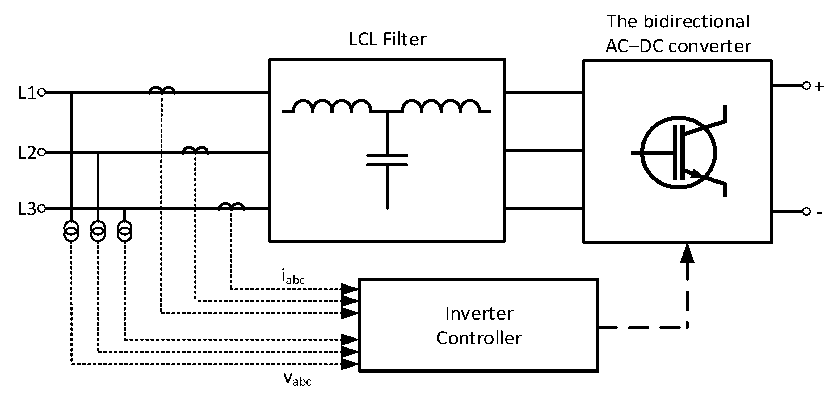
The model shown in
Figure 8 uses an active rectifier with a MOSFET transistor bridge. This ensures a two-way electricity flow. In G2V mode, the bidirectional AC-DC converter can rectify the three-phase supply voltage to DC [
42]. When the rectifier works in V2G mode, it can convert the DC voltage to AC and transfer the power back to the mains [
43].
3.2. Modeling of Low-Voltage Grids
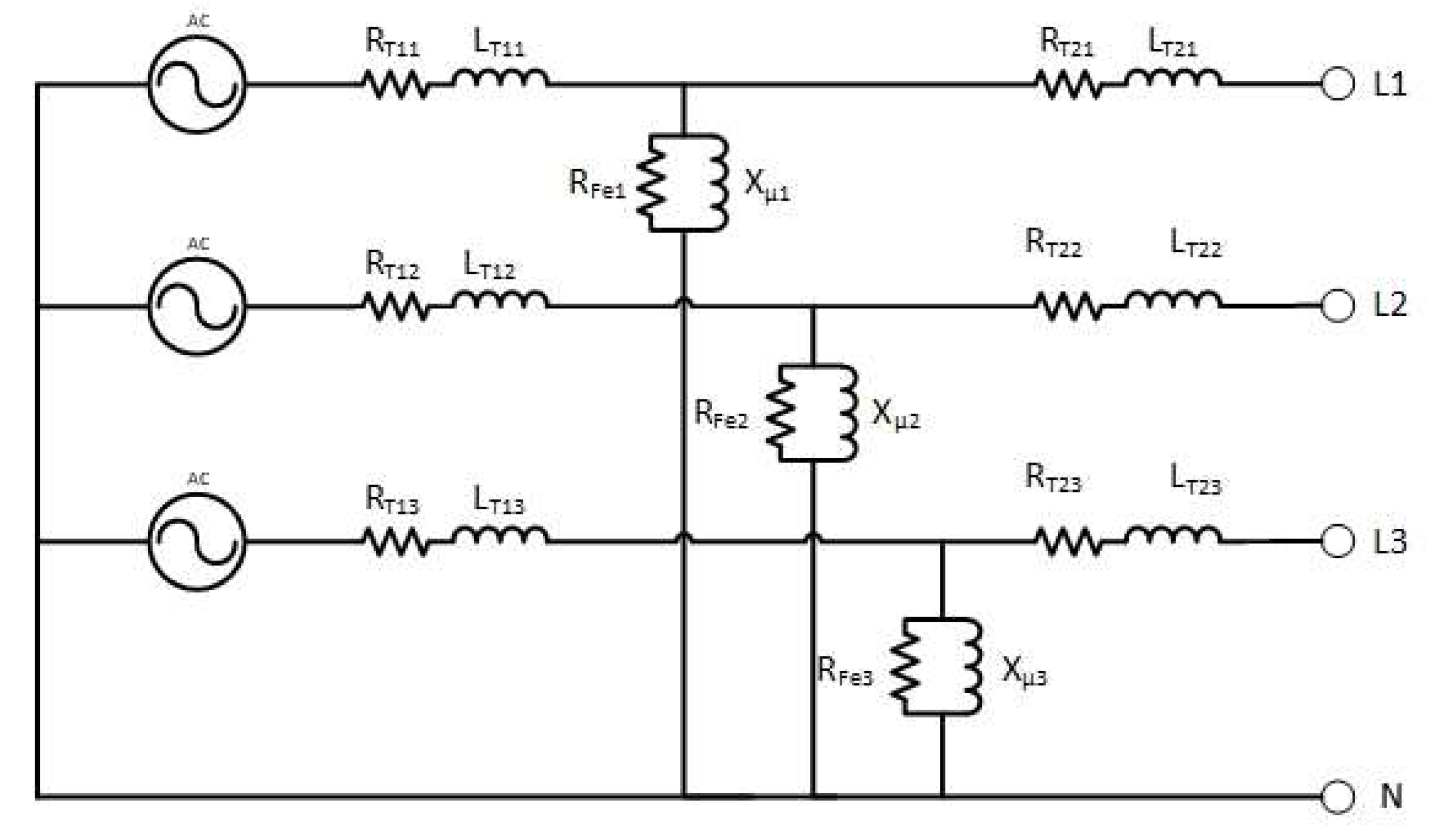
In the simulation model, the actual distribution network supplied from the medium-voltage/low-voltage transformer (MV/LV transformer) station was used. The parameters of the power supply transformer, such as rated power, rated frequency, core starts, winding losses, magnetization reactance, winding dispersion, and primary and secondary voltage, were considered.
Figure 9 shows the diagram of the transformer model.
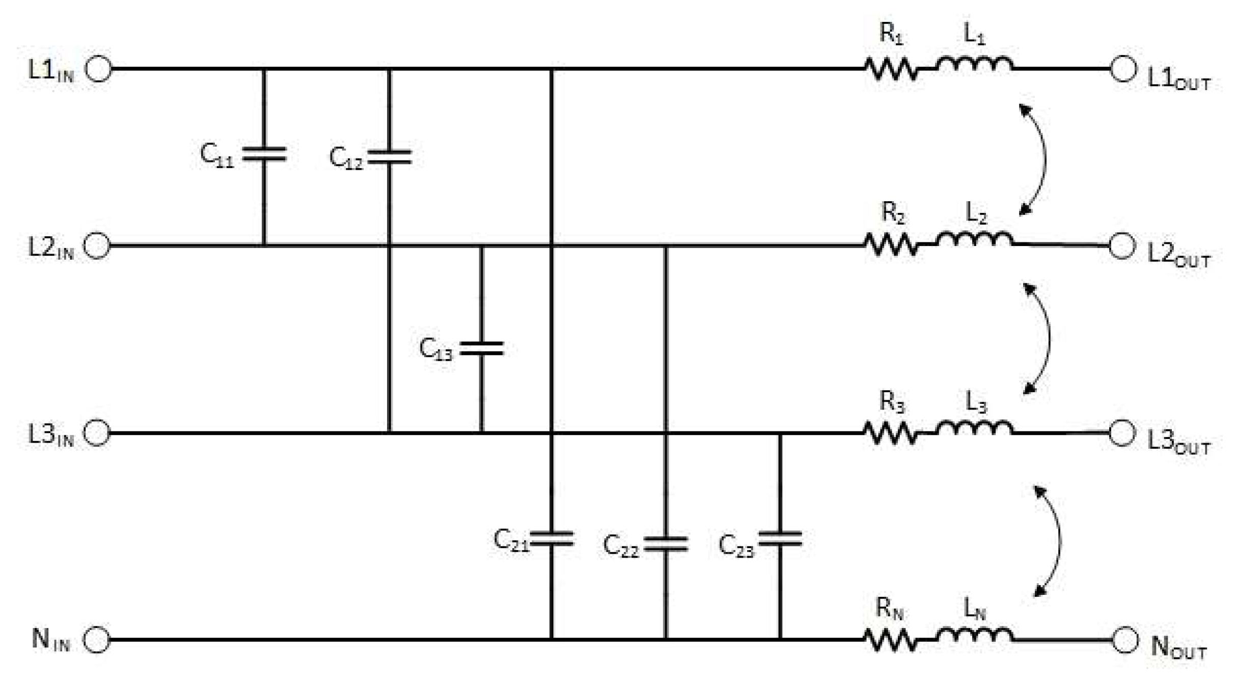
Cable line models used in simulations (
Figure 10) were developed using data provided by cable manufacturers. The transverse and longitudinal parameters of low-voltage cable lines (capacitive and inductive reactance and resistance) were considered.
The selection of the cable model considered the power of individual loads, acceptable voltage drops, long-term current-carrying capacity, and the requirements for protection against electric shock, which directly contributed to the construction of networks with specific parameters and lengths of power supply lines dictated by design calculations. Due to these procedures, the network was not overloaded even once during the simulation, and the manufacturer’s recommendations and general technical knowledge in the field of power equipment selection were followed.
Technical data of aluminum cables with polyvinyl insulation were taken from the manufacturer’s catalogue [
44]:
YAKY 4 × 240 mm2 − R = 0.125 Ω/km, L = 0.223 mH/km;
YAKY 4 × 150 mm2 − R = 0.206 Ω/km, L = 0.23 mH/km;
YAKY 4 × 240 mm2 − C = 1.32 μF/km;
YAKY 4 × 150 mm2 − C = 1.25 μF/km.
According to the manufacturer information [
44], the mutual capacitance of any pair of wires is roughly 60% of the value given for the whole cable.
4. Results
Simulation studies were conducted for the developed models of chargers and networks, and the results are presented in this chapter. In each case, a low-voltage network powered by a 630 kVA transformer station was modeled. For chargers with smaller power (22 and 40 kW), the power line was a reproduction of an aluminum cable with a cross-section of 150 mm2. On the other hand, the 200 kW charger was modeled on a 240 mm2 aluminum cable due to the higher rated current.
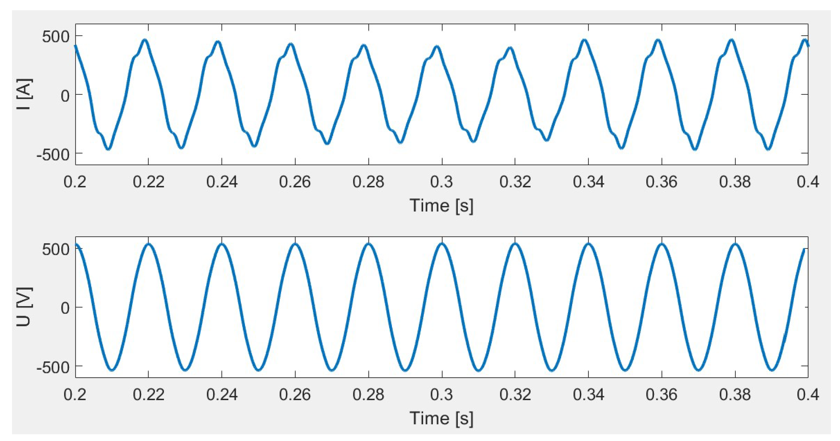
4.1. Simulation of 22 kW and 40 kW Chargers
Two cases where the low-voltage grid has been loaded with several chargers operating in one circuit were investigated. For both situations, the worst conditions for the network were modeled in terms of load. It was calculated that a 200 m long line made with a 150 mm
2 aluminum cable can be loaded with up to seven 22 kW chargers or four 40 kW chargers. As the standards do not currently provide for a simultaneity factor to be considered when making the calculations, it was assumed that all the chargers work simultaneously. The simulation results are shown in
Figure 11 and
Figure 12.
In both cases, the voltage is not substantially deformed; the THD
U coefficient reached a value of less than 1% for a situation in which four chargers with a power of 40 kW operate simultaneously on a given network and is slightly lower than that in the case of seven chargers with a power of 22 kW operating simultaneously. The THD
I value in both tests was approximately 10%. The conditions given in the standard [
21] were met.
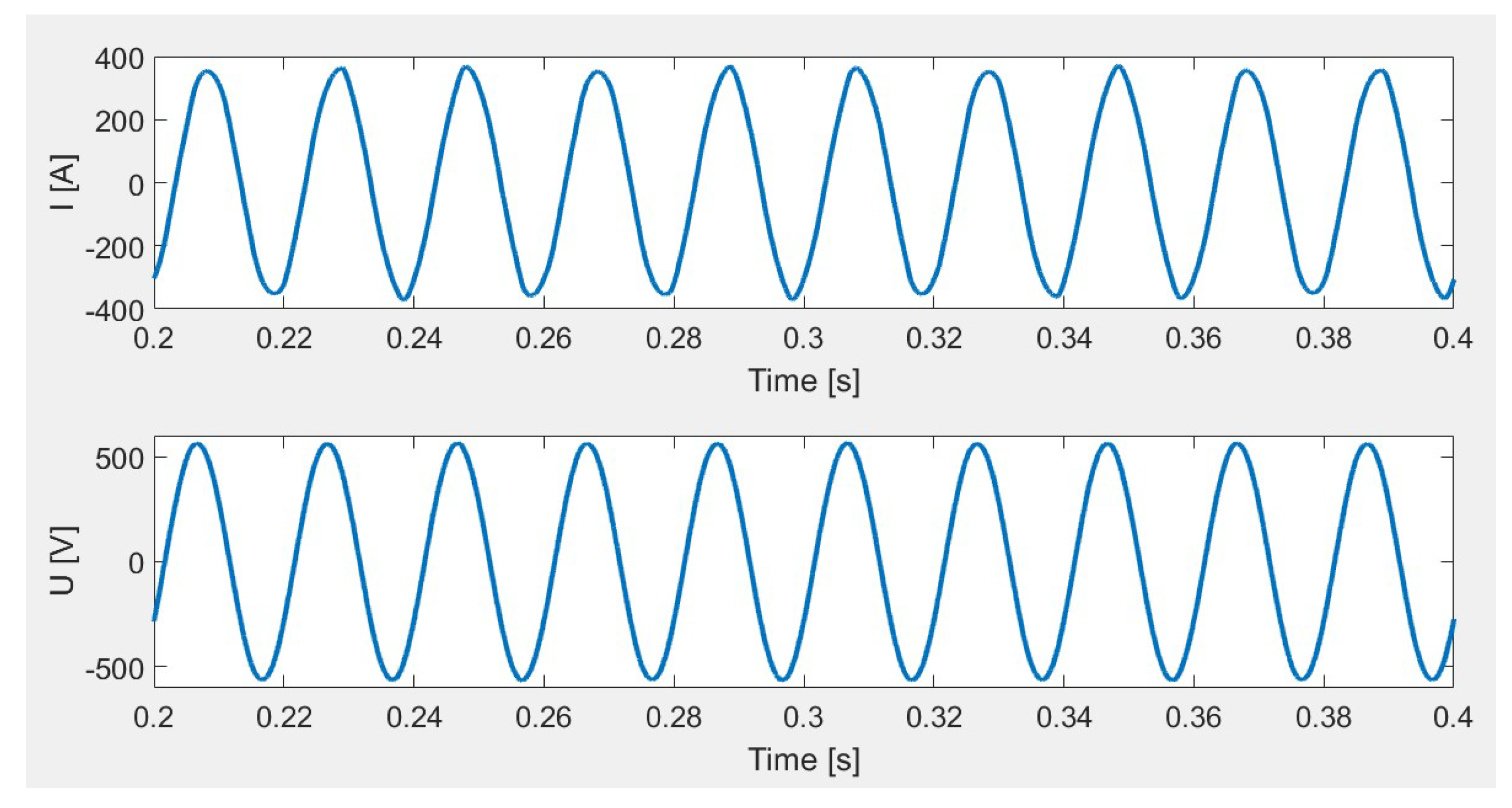
4.2. Simulation of 200 kW Chargers
Due to the value of the rated current, for 200 kW chargers, the line made with a 240 mm
2 aluminum cable is used in the model of the mains supply. It is assumed that the maximum length of the line is 250 m. In all the simulations, the following elements were taken into account: loads, current-carrying capacity, permissible voltage drops, requirements for protection against electric shock, and network typology. The worst case was when the length of the cable reached 250 m and yet the requirements of technical standards were met. As mentioned in the previous experiment, the most unfavorable conditions of network operation in terms of load and line length were modeled. The results of the simulation tests are presented in
Figure 13.
As in previous cases, for a high-power charger, the current and voltage waveforms are not deformed. The THDU and THDI values of 2.3% and 5.45%, respectively, are also satisfactory.
4.3. Simulation of 40 kW V2G Chargers
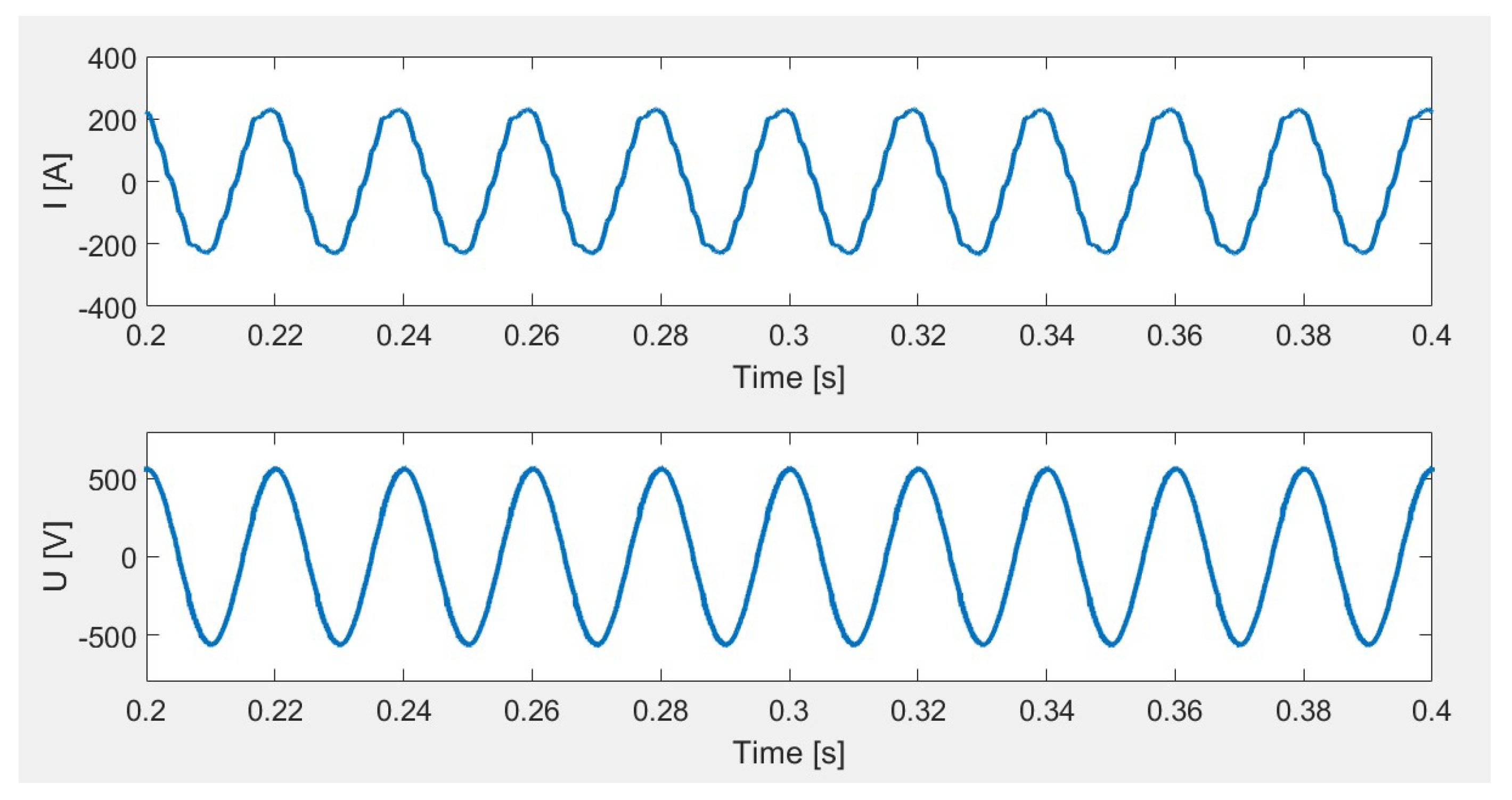
The following simulations show a case in which four 40 kW chargers worked in a V2G configuration and transferred energy from batteries in electric vehicles charged to 80% to the mains. The grid model was additionally loaded with a load of 10 kvar. The results of the simulation tests are shown in
Figure 14.
The simulations showed that the maximum load on the mains with chargers operating in the V2G mode also had no negative impact on the voltage deformation. The THD
U coefficient did not exceed the values required by the standard [
21]. However, the current drawn from the transformer is significantly deformed, and the THD
I coefficient is 31.7%.
5. Discussion
On the basis of the developed models, simulation tests were carried out to assess the impact of electric vehicle charging systems on electricity quality. The development of faithful simulation models of charging stations and the assessment of their impact on electricity quality is possible, but at the same time, because of the multitude of solutions that can be adopted, it is also difficult and complicated. Furthermore, to assess the impact of electric vehicle charging systems on electricity quality by using simulations, it is necessary to model in detail not only the charging stations themselves but also the individual elements of the electricity grid, i.e., the transformer and power lines. Other connected loads and their possible impact on the grid should be considered.
As expected, the experiments have shown that the more converter systems are in one circuit, the greater the deformation is in the course of the current and voltage.
The design of a reliable model of a charger needs proper identification of the topology of the rectifier system, the filters used on the AC and DC side, the power of the charger, but above all, the type of charger. These data are not readily available from charger manufacturers but can be obtained from recording the current and voltage waveforms of a charger operating in the idle mode and, above all, in the charging mode. The rectifier used in the charger has a decisive influence on the shape of the current drawn from the distribution network by the charger. This hypothesis has been proven by the presented simulations.
The experiments showed that there are cases where the THDI coefficient exceeds 10%, which may indicate that the charging stations will have a negative impact on other devices operating in a given network, and that there may be an increase in the temperature of cables and supply lines. Bearing in mind that for distribution and transmission networks, power losses are important and may affect the efficiency of the entire power system, it is necessary to review and evaluate the existing standards defining the content of higher harmonics of current generated by devices in an era of an increasing number of converter systems in power supply networks. This is important because, contrary to the THDU value, the permissible THDI values are not defined by any regulations or laws. Cables and transformers act as low-pass filters, which affects the shape of the current drawn by chargers and voltage deformations. The standards, which currently define the principles of designing power networks, considered only the parameters of power supply lines and the power required by a given reception. They do not give the rules of selection of, for example, cables or transformers, in case several chargers of electric vehicles are to operate in one circuit. It should be clearly stated how the saturation of the network with electric vehicle chargers will affect the operation of this network. The consequence of such an analysis should be the development of new technical regulations that determine the principles of the selection of cables and wires by considering their heating under the influence of higher harmonic currents generated by electric vehicle charging systems and possible voltage deformations resulting from non-sinusoidal currents drawn by chargers.
Chargers operating in the V2G mode may be used in the future as one of the elements of the smart grid, as such systems will be able to act as reservoirs of electricity, which may be returned to the grid at a given time. With the relevant legislation, market model, and awareness of electric car users, this will have a direct impact on shaping the daily electricity demand curve.
6. Conclusions and Future Work
The simulations performed show that there is some influence of electric car charging systems on the quality of electricity. However, while maintaining appropriate design standards for this type of devices, this impact may be insignificant. Taking into account the large number of solutions that can be used by producers, it is recommended to revise the currently used norms and technical standards and develop new ones aimed directly at this branch of the power industry. Particular attention should be paid to the fact that despite correctly selected power cables and transformers, voltage and current distortions may occur. Therefore, it is recommended to develop network models and perform simulation tests in addition to electrical calculations based on technical standards.
Further work of the authors will focus on the development of assumptions clarifying the manner of cooperation between chargers and the distribution network. Authors will focus their research on chargers with the V2G service, which can be used in the future as mobile energy storage and can be used to smooth the daily load curve. The main target is to describe rules and requirements for connection V2G chargers to the distribution grid. The authors see many advantages and opportunities offered by chargers with the V2G service. They will prepare analyses for the implementation of V2G chargers as mobile energy storage for microgrids.


