Abstract
Focusing on the transitional depth offshore area from 50 m to 75 m, types of articulated foundations are proposed for supporting the NREL 5 MW offshore wind turbine. To investigate the dynamic behaviors under various water depths, three articulated foundations were adopted and numerical simulations were conducted in the time domain. An in-house code was chosen to simulate the dynamic response of the articulated offshore wind turbine. The aerodynamic load on rotating blades and the wind pressure load on tower are calculated based on the blade element momentum theory and the empirical formula, respectively. The hydrodynamic load is simulated by 3D potential flow theory. The motions of foundation, the aerodynamic performance of the wind turbine, and the loads on the articulated joint are documented and compared in different cases. According to the simulation, all three articulated offshore wind turbines show great dynamic performance and totally meet the requirement of power generation under the rated operational condition. Moreover, the comparison is based on time histories and spectra among these responses. The result shows that dynamic responses of the shallower one oscillate more severely compared to the other designs.
1. Introduction
As a clean energy resource, wind power presents an attractive and competitive source among different renewable energies, including wave, tidal, solar, biomass, and others. Compared with onshore wind resources, the strength and steadiness of offshore wind is much better. It is estimated that the offshore wind energy resources are nearly three times higher than onshore. Therefore, more and more attention has been paid to the research of offshore wind turbines (OWTs), and they have been fully developed in the past decades [1]. Besides, due to the mature installation technologies and relatively low construction cost, offshore wind energy development was expanded rapidly in the past years [2,3]. According to statistic data, the installed offshore wind power capacity in 2017 was 4.33 GW all over the world, and the cumulative installed capacity was 18.81 GW, which was 17 times more than in 2007 [4].
Typically, when we talk about offshore wind turbines, there are two main types of foundation to support them. One kind are fixed foundations, including gravity base, monopile, tripod, and jacket foundations [5]. These fixed foundations are usually installed in the sea area less than 50 m. In fact, the fixed foundation should bear the environmental and operational loads. When the water depth increases, the bending moment at the seabed increases greatly. In order to resist this large moment, the scale of the structure needs to be increased, causing a substantial increase in the construction and installation cost.
To overcome this issue in the deep-water area, the other kind of offshore wind turbine supported by a floating foundation was proposed. Generally, floating foundations employ customized technology from the deep-water oil and gas industry [6]. Spar, TLP (Tension Leg Platform), and Semi are typical foundations that have been widely used at different levels of the deep-water field. At present, the water depths of most European offshore wind farms are over 100 m, as shown in Table 1. According to experimental and numerical investigations, their stability and dynamic performance have been validated [7,8,9,10,11,12].

Table 1.
Offshore wind farms in Europe.
Specifically, the mooring line is one of the essential parts in order to limit the drift displacement of floating offshore wind turbines (FOWTs). However, its effect is dependent on the water depth. In other words, the deeper the water, the better the restoring performance. Nevertheless, the offshore scenario in China is totally different from Europe. The overall water depth of the southeastern coastal area is about 50 to 80 m, even in offshore areas which are about 20 km from the coastal line. It is a great challenge to establish a floating or fixed OWT in these areas both economically and safely.
Therefore, in order to meet the development needs for offshore wind energy in the southeastern coastal area, a new wind turbine foundation that is suitable for water depths less than 100 m becomes a big strategic demand in China. Many efforts have been made to invent new types of FOWTs in order to reduce the draft [13,14,15,16,17]. According to numerical simulations and experimental tests, the dynamic performance of these designs has been validated, but their feasibilities in shallow water are not fully investigated.
As one kind of classic offshore platform, both single-hinge and multi-leg articulated towers have been validated for numerous applications, including crude production, single-point-mooring system foundations, and so on [18,19,20]. In recent years, the hydrodynamic response study of this classic structure has attracted some scholars’ attention. Gavassoni et al. [21] established a two-degree-of-freedom (DOF) discrete numerical model to study nonlinear oscillations of an articulated tower platform. They observed complex nonlinear features in the dynamic response, such as multiplicity of modes, stable and unstable free vibration modes, bifurcations, etc.
Meanwhile, much more research has been conducted on dynamic behaviors under complex sea conditions. Zaheer and Islam [22] established a two-DOF analytical model to investigate the motion of a double-hinged articulated tower under combined wind and wave. On the other hand, Javed [23] carried out a series of numerical simulations aiming at studying the seismic influence on the hydrodynamic performance of a single-hinged articulated tower. They found that these extreme environmental loads would significantly change the dynamic response of the articulated tower, including motion oscillation, shear, axial force. In some particular cases, nonlinear vibrations, such as subharmonic and superharmonic responses, were also observed.
In recent decades, articulated foundations are gradually adopted to support offshore wind turbines. Wu et al. [24] proposed a single-articulated-hinge offshore wind turbine, which was applicable to 90 m water depth. They established a single-DOF model to calculate its dynamic response under the regular wave. The results proved that the structure showed good hydrodynamic performance. Similarly, Philip et al. [25] conceptually designed a three-leg-hinged supporting foundation for 5 MW offshore wind turbine in a 150 m depth area. They studied the motion response of the whole system under different wind and wave scenarios. Joy et al. [26] conducted a group of experiments on the three-leg hinged 5 MW wind turbine with a scale ratio of 1:60. According to the results, they found that the natural frequency was far away from the wave frequency. Based on their work, Navin et al. [27] simulated the environmental load on this wind turbine, observing the dynamic responses in the time domain. Furthermore, they also analyzed the fatigue strength of the structure. All the above works show that this articulated tower foundation is feasible to support the offshore wind turbines.
In this study, we proposed an articulated offshore wind turbine (AOWT) based on the articulated tower platform. It is hinged at the seafloor, rather than fixed at the bottom of the sea. Therefore, the torque caused by the environment load is unleashed to avoid increasing structure size. Hereby, it could greatly cut the construction material by adopting this supporting foundation. Besides, based on the current structure of the articulated wind turbine, we made some improvements. The ballast tank is set on the lower position, while the buoyancy tank is set near the water surface. At present, we have finished the preliminary design of the whole structure and conducted the feasibility verifications for 50 m, 70 m, and 75 m water depth, respectively. Their dynamic responses, including the tilt motion of the articulated foundation, the aerodynamic performance of the rotor, and the tensions on the hinge are further compared in future works.
The AOWTs proposed in this work provide a new type of offshore wind turbine foundation corresponding to a water depth from 50 m to 100 m, which fills the technical gap in such water depth range and greatly solves the technical limitation due to the special landform in the sea area of the South China Sea. Specifically, on one hand, compared with the fixed foundation wind turbine, the AOWTs are smaller in size, and their construction cost will be lower. This is because the total structure rotates around the hinged point. According to this approach, the overall structure can effectively avoid the huge bending moment on the seabed and reduce the failure probability. On the other hand, when they are compared with FOWTs, AOWTs have benefits such as a simpler structure and shorter construction cycle. Furthermore, the establishment and installation cost will be reduced because the mooring system is no longer necessary, under the help of the restoring moment provided by both main body and tanks.
In the following study, an in-house coupled model of AOWT is developed. Based on the potential flow theory, the wave–body interaction is calculated with stochastic waves. The aero loads on the rotating blades are calculated by the blade element momentum theory. The hydrostatic restoring load is calculated by the geometry relationship. Besides, the friction damping of the articulated hinge is also taken into consideration according to the empirical formula.
In the following sections, the configuration and physical parameters of the AOWT system will be defined first. Afterwards, the numerical models (including the restoring model, the joint hinge friction model, the aerodynamics model, and the hydrodynamics model) are briefly described. Numerical results, including predictions of dynamic responses under wave, wind, and current loads, are then presented and discussed. Finally, conclusions are drawn.
2. Physical Problem Description
As shown in Figure 1a, the AOWT mainly consists of the NREL 5 MW baseline wind turbine [28] and an articulated-tower support foundation. Detailed parameters of the upper wind turbine could be easily found from previous work or other, similar research [28,29]. On the other hand, the support platform consists of a perforated column, a buoyancy tank, and a ballast tank. The vertical configuration of the articulated foundations is shown in Figure 2. To investigate the dynamic responses of the AOWTs under different water depths, these three main parameters are optimized based on the algorithm from the perspective of motion stability and economy. The main parameters for each foundation are listed in Table 2. More details about this optimization progress could be found in our previous works [30,31]. Besides, considering the welding of the main structure, subdivision bulkhead, and reinforced aggregate, the equivalent thickness of the foundation is 0.07 m. Hereby, (x, y) is a two-dimensional Cartesian coordinate system with its origin at the bottom of the hinged joint and y pointing upward (see Figure 1b). The x-axis coincides with the direction of the incoming wind and wave.
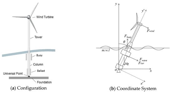
Figure 1.
Articulated offshore wind turbine.
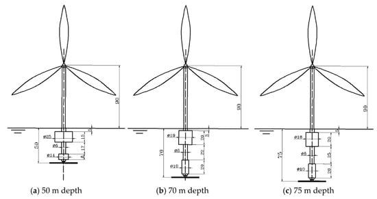
Figure 2.
Articulated offshore wind turbine.
Table 2.
Main design parameters of the articulated offshore wind turbine (AOWT).
3. Methodology
3.1. Governing Equation
According to the design of the articulated tower platform and related numerical theories, the analysis model of AOWT can be mainly divided into three categories: single-DOF rigid model, two-DOF rigid model, or multi-DOF elastic model. During the initial design progress, the first model is usually adopted for simplification. Hereby, we adopted this model in the following simulation.
Different from typical fixed or floating offshore wind turbines, the AOWT is hinged at the seabed. In other words, the translational motions, including surge, heave and sway are limited, while the rotational motions are allowed. In this study, we consider the wind and wave are in the same inflow direction, applying consistent environmental forces on the structure. Thus, the equation of rotation in this direction, which we called pitch motion, is first established. Then we calculate its amplitude-frequency response in the frequency domain. Damping effects, including radiation damping, viscous damping, and friction damping of the articulated joint; hydrostatic restoring force; and wave excitation force are all taken into consideration. Therefore, the frequency domain equation is given as
where is the system moment of inertia, is the added moment of inertia, and are radiation damping coefficient and viscous friction damping coefficient respectively. The former term is calculated based on the potential theory, and the determination algorithm of the parameters in the latter term could be found in the following subsection. is the restoring stiffness of the system, is the wave force in frequency domain, is wave frequency, and is the phase angle. Hereby, the motion response of the articulated offshore wind turbine in the frequency domain can be obtained by solving Equation (1).
Furthermore, to study the dynamic performance under the combined action of wind and wave, the dynamic governing equation is developed to calculate the displacement, velocity, and acceleration of the AOWT. The Cummins Equation and convolutional method are adopted to establish the time-domain equation. Thus, the governing equation can be written as
where is the retardation function, and is the added mass when the frequency approaches infinity. Both of these two terms are determined by the convolutional approach of the frequency-dependent added mass and potential damping. and denote the damping and restoring coefficients, respectively. represent the pitch angle, angular speed, and angular acceleration, respectively. are the external environmental loads, including the wave and current loads on the articulated foundation, the aerodynamic loads on the rotor, and the wind pressure on the tower. This approach is demonstrated to be sufficiently accurate for predicting the nonlinear motion of the articulated offshore oil and gas platform [32].
3.2. Friction Damping
For spherical articulated joints, the friction damping moment can be obtained from the following formula [29].
where is the friction coefficient, for which we take the empirical value 0.1. denotes the normal force, is the radius of the spherical articulated joint for which 1.5 m is adopted. represents the unit vectors in the same direction as the angular velocity vectors.
In the numerical model, the overall damping, including the viscous damping on the articulated foundation and the friction damping on the articulated joint, is assumed as the percentage of the critical damping in the following expression [33].
where, denotes the dimensionless damping ratio; in the following simulations, the value of 0.055 is adopted. It consists of a 5% viscous damping term [34] and a 0.5% articulated joint friction term [35]. These damping coefficient values are adopted in both frequency and time domain simulations.
3.3. Restoring Force
The restoring moment is calculated by the following formula,
where is the buoyancy of the articulated foundation, is the moment arm of buoyancy to the hinged joint, is the total mass of the whole structure, and is the moment arm of gravity to the hinged joint.
Specifically, according to the previous simulation, we found that the hydrostatic restoring force of the articulated tower was nonlinear [30]. Nevertheless, from the stability curve, the restoring moment curve could be approximately linear when the inclination angle is less than 20 degrees. When conducting the frequency domain analysis, we assumed that the restoring moment term is linear and the restoring stiffness is defined by the slope at the origin of the stability curve.
3.4. Environmental Loads
There are three kinds of environmental loads included in the following simulation. They are wind loads on the turbine, wave, and current loads on the articulated foundation, respectively. Detailed theoretical methodologies for corresponding loads are described.
3.4.1. Wind Load
The wind load on the wind turbine includes the aerodynamic load on the rotor and the wind pressure load on the tower. The aerodynamic load is calculated based on the blade element momentum theory [36]. The axial thrust and torque on each blade element are
where is air density. To be specific, according to the metocean data of the South China Sea, the temperature can hardly decrease to the average level in the cold climate. Here, the standard air density is adopted in the simulations. is the resultant wind speed, is the number of blades, is the chord length of the blade element, and are the lift and drag coefficients, respectively, is the inflow angle, is the distance from the local element to the hub, is the length of the blade element, and is the Prandtl loss factor, calculated by the following formula.
where is the radius of the entire impeller, and is the hub radius.
Another component of wind load is the pressure on the tower. It is calculated based on the classical empirical formula [37],
where is the total number of components. We divided the tower into 10 pieces in the direction of altitude; hence, is 10. is the height coefficient, is the shape coefficient, is the projection area of the corresponding part when the wind direction angle is , and is the relative wind speed corresponding to different heights.
Hereby, the total wind moment is achieved from the following equation,
where is the moment arm of aerodynamic thrust to the hinged joint, and is the moment arm of wind pressure on tower to the hinged joint.
When the wind turbine has a large tilt angle motion, there are two main cases. One case is due to the large average pitch angle, but the oscillation is relatively small. This case usually occurs when the wind speed gets large. In this case, the Boundary Element Momentum (BEM) approach is fairly accurate which was validated in our previous study on the Spar-type FOWT [38]. Its accuracy was validated with both model tests and full-scale tests [39,40], and the numerical module has been proven by comparing with Aerodyn [30]. Meanwhile, when the wave height gets large, the oscillation increases significantly. We believe that this quasi-static approach should be further improved or even replaced by other methods, such as the Computational Fluid Dynamics (CFD) approach, to enhance the simulation accuracy.
3.4.2. Hydrodynamic Loads
The wave load on AOWT is calculated by three-dimensional potential flow theory, which is a classic but widely used approach in the dynamic simulation of offshore structures. The velocity potential is decomposed into incident potential , diffraction potential , and radiation potential . All components will meet the requirement of the Laplace equation. Thereby, they could be solved according to the theory of Airy wave under free surface conditions as well as the boundary conditions. The water pressure of the fluid is solved according to the Bernoulli equation, and the wave load of the floating body is integrated along the wet surface of the submerged body.
In the present work, the wave–body interaction is calculated based on the 3D potential theory in the frequency domain by using the DNVGL software WADAM. As a primary design, the linear wave load is taken into account. Specifically, to perform the dynamic simulation in the time domain, the random wave forces are transferred into time series by multiplying these hydrodynamic parameters and the specified wave spectrum in the complex domain. In other words, the wave load is calculated based on the following equation,
where , , and φj denote the wave amplitude, the circular wave frequency, and the initial phase angle corresponding to the j-th wave component. represents the hydrodynamic transfer function that contains a linear transfer function (LTF).
The wave load calculation module has been validated under different wave scenarios, including normal, survival, and freak wave conditions. The validation is conducted among the results of other established numerical models (e.g., FAST, SESAM), other published works, and model tests, and the accuracy is demonstrated. More details can be found in [41,42,43].
3.4.3. Current Load
Current loads on the supporting foundation are calculated in accordance with the China Classification Society (CCS) standard [44], as per the following formula.
where means the drag coefficient, is the seawater density, is the projection area of the component on the plane perpendicular to the velocity of current, and denotes the relative velocity of the current. As the major body of the articulated foundation is a cylinder, the value of the drag coefficient is assumed as 0.7 in the following simulations, based on the recommendation of the CCS [45]. Moreover, the simulation accuracy of the current load module has been validated in our previous publication by comparing it with the model test of a Spar-type FOWT [38].
3.5. Flow Chart of Simulation
Based on the algorithms above, a coupled aero–hydro dynamic simulation tool for AWOT is developed in the time domain. The basic procedure of this coupled numerical simulation is shown in Figure 3.
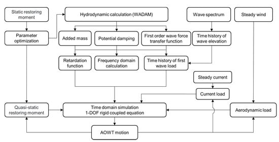
Figure 3.
Flow Chart.
In fact, this simulation tool was further developed from our previous code for the Spar-type FOWT [30]. The modules in this paper were validated in our previous study [31]. The BEM and 3D potential flow approaches we used are well established, and their accuracy has been tested in these publications. Therefore, most of the modules, such as the hydrodynamic coefficients transformation, wave and wind generation, retardation function calculation, fourth-order Runge–Kutta numerical solution, and so on, were validated in our previous work. Although the simulation tool was first adopted to calculate the dynamic response of an AOWT, it was validated by FAST and other experimental results of FOWTs. However, there are few studies about the articulated wind turbine; hence, we can hardly compare our results with other works.
4. Results
We established the numerical model to simulate the dynamic response of AOWT, considering the combined effect of wind, wave, and current. Firstly, the hydrostatic model is adopted to calculate the restoring moment via different trim angles. Then the hydrodynamic results are shown to describe the natural features of AOWTs. The rated operational sea state is considered (see Table 3). This scenario is adopted from the recommendation of an international standard IEC 61400 [46]. Moreover, according to the metocean statistics of the joint probability distribution in the South China Sea [47], the values of wind and wave parameters are determined corresponding to the operation status and safety of the wind turbine. Specifically, the JONSWAP spectrum is adopted to generate the irregular wave elevations in the simulation. Among the results, we focus on the pitch motions of structure, as well as the aerodynamic performance of the rotating blades and reaction of the hinged joint.
Table 3.
Rated operational sea state.
4.1. Wave–Body Interaction Performance
4.1.1. Hydrostatic Analysis
In order to meet the requirements of the air gap, the bottom of the articulated tower should be 10 m above the still water plane, and the maximum pitch angle of the articulated foundation under the extreme condition should be less than 20° [48]. When the flange edge of the articulated foundation column and wind turbine tower is submerged, the exact pitch angle is defined as the flooding angle. According to the configuration and geometry relationship, we found that the flooding angle of the designed AOWT is 26°. In other words, the flooding angle is guaranteed to meet the requirement under extreme conditions. Moreover, for the whole AOWT system, the restoring moment curve under large pitch angles is calculated based on Equation (5). The results of three AOWTs are shown in Figure 4.
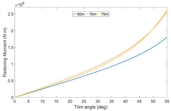
Figure 4.
Articulated offshore wind turbines hydrostatic restoring moments via different trim angles.
In Figure 4, the restoring moments almost remain linear when the trim angle is less than 30° for all three AOWTs. However, when the tilt motion exceeds this extreme, the nonlinear restoring moments will be observed. However, as the allowed maximum dynamic oscillation pitch angle which is usually 15° under the operation condition [29], the restoring term in the Equations (1) and (2) could be approximately recognized as a linear term when the AOWTs are operating under the normal condition.
Another interesting phenomenon was found; the restoring moments of the 70 m depth AOWT are larger than those of the other two AOWTs under most trim angles. In fact, according to Equation (4), we found that the restoring moment is determined by two factors, the buoyancy term and the gravity term, including the forces and their corresponding arms. On one hand, comparing with the other two AOWTs, the 50 m one has the shortest righting arm due to the shallowest water depth. Therefore, its restoring moment provided by the foundation is less than other two articulated foundations. On the other hand, because the buoyancy tank diameter of the 70 m depth AOWT is a little larger than the 75 m depth one (see Table 2), the restoring moment is slightly increased by this effect.
4.1.2. Hydrodynamic Analysis
According to Equation (1), an in-house code was programmed to simulate the dynamic response of AOWT in the frequency domain. As the main motion of the overall structure is the oscillation around the hinged joint, a single-DOF equation is established. In the following simulations, the pitch motion is adopted to evaluate the hydrodynamic performance of different articulated foundations. Hydrodynamic and damping coefficients were calculated through the commercial software WADAM which is based on the 3D potential flow theory. These coefficients were input to the code to obtain the response amplitude operators (RAOs), as is shown in Figure 5. Moreover, the natural frequencies and periods of pitch motion for each AOWT are listed in Table 4.
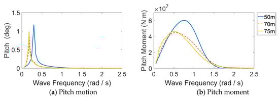
Figure 5.
Response amplitude operators (RAOs) of articulated offshore wind turbines (AOWTs).
Table 4.
Natural features of the AOWTs.
According to Figure 5 and Table 4, it can be seen that the natural periods of AOWT avoid common wave periods (conventional range comes from 5 s to 20 s), although that of 50 m depth AOWT is larger than the others. In other words, a large resonance motion can hardly be excited. On the other hand, the rated speed of the NREL 5 MW wind turbine is 12.1 rpm; hence, the 1P frequency of aerodynamic load is 1.27 rad/s, while the 3P frequency is 3.80 rad/s. The natural period of the system pitch motion effectively avoids the 1P and 3P load frequencies of the rotating blades; hence, the internal resonance in the common articulated structure could also be avoided. Furthermore, according to the results in Figure 5b, the amplitude wave loads of the 50 m depth AOWT in the range of common wave periods are over 50% higher than the other two AOWTs. This is caused by the larger diameter of the buoyancy tank which is close to the free surface.
4.2. Dynamic Response under Operation Conditions
In this section, the dynamic response of AOWTs is examined under three operational conditions shown in Table 3. In the following simulations, the total duration is 3600 s, and the time step is 0.1 sec. After the first 600 s of initial start-up oscillations, the remaining samples (30,000) are adopted for a results analysis, including data statistics and Fast Fourier Transformation (FFT) post-processing. Specifically, in order to make the time-domain results more comparable, we adopted the same wave elevation history in the simulations. Hereby, the results are shown in Figure 6. To be specific, the FFT postprocessor function is the discrete Fourier transform tool in MATLAB [49,50]. To show the dominant frequencies more clearly, we adopted the amplitude spectra for all frequency-domain analyses, and the logarithmic scale was used for the y-axis of every spectrum. In the following subsections, the motion, aerodynamic performance, and tension on the hinged joint of the AOWTs under different water depths are analyzed and discussed, respectively.
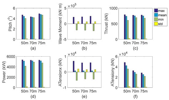
Figure 6.
Statistic results of motion, aerodynamic performance, and hinged joint tensions. (a) Pitch angle (b) Wave moment in pitch (c) Thrust on the rotor (d) Output power (e) x-direction Tension on the articulated joint (f) y-direction Tension on the articulated joint.
4.2.1. Pitch Motion
The time history curves and response spectrum of pitch motion are displayed in Figure 7. According to the simulation results, the pitch of AOWT is smaller than that of OC3 Hywind FOWT [38]. Among different water depths, we can see that the pitch motions differ in both mean position and dynamic oscillation. On one hand, according to the results in Figure 6a and Figure 7a, it can be seen that the average pitch of the 75 m depth AOWT is the largest among the three AOWTs, while the 70 m depth one shows the least average motion.
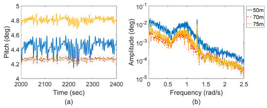
Figure 7.
Dynamic response of pitch angle. (a) Time histories of pitch angle (b) Response spectra of pitch angle.
This phenomenon is caused by restoring moment and environmental loads which contain the steady term and influence the equilibrium positions. External environmental loads, such as the wind thrust and pressure, the current drag, the higher-order drift wave force, are all included in the simulation. On one hand, based on the hydrostatic results in Figure 4, we could find that the 70 m depth AOWT has the greatest restoring moment, which is beneficial to reduce the mean pitch angle. On the other hand, although the restoring moment of the 75 m depth AOWT is more than the 50 m depth one, its environmental loads are the largest among the three concepts. As a result, the mean pitch angle is enlarged.
Moreover, from the response spectrum in Figure 7b, it can be seen that there are three peaks in each pitch angle response spectrum. According to the order of response frequency, they respectively correspond to the natural frequency response, wave frequency response, and 1P frequency response resulting from rotating blades.
Furthermore, according to the time history curves and spectrum in Figure 7, we see that the standard deviation of pitch motion differs among these AOWTs. The standard deviation is representative of the oscillation amplitude around the new equilibrium position. By comparing the results among these conditions, it is seen that the oscillation of the 50 m depth AOWT is much larger than the other ones. On the other hand, the response spectra of the 70 m and 75 m depth AOWTs agree well with each other, even though the dominant responses of the 70 m depth AOWT, such as low-frequency and wave-frequency response, are slightly lower than those of the 75 m depth one.
In fact, this difference is mainly due to the various damping values adopted in the models. Although the same critical damping coefficients are used in three models, the total damping values are different due to the inertia and stiffness, as Table 5 shows. In fact, this is due to the column length. With the shorter length, the viscous damping of the 50 m depth AOWT is smaller than the others. Hereby, not only the wave-frequency response but also the low-frequency and 1P-frequency responses are amplified.
Table 5.
Dynamic parameters of the AOWTs.
4.2.2. Aerodynamic Performance
The time history curves and response spectrum of thrust and output power are displayed in Figure 8. From Figure 8a,c, it can be seen that the average value of thrust and output power are similar in all three cases. Comparing the pitch motion response, the variation trends of aerodynamic performance in these three cases are almost the same. Moreover, the output power is basically stable at the rated power 5 MW. In other words, the feasibility of the AOWTs is further validated.
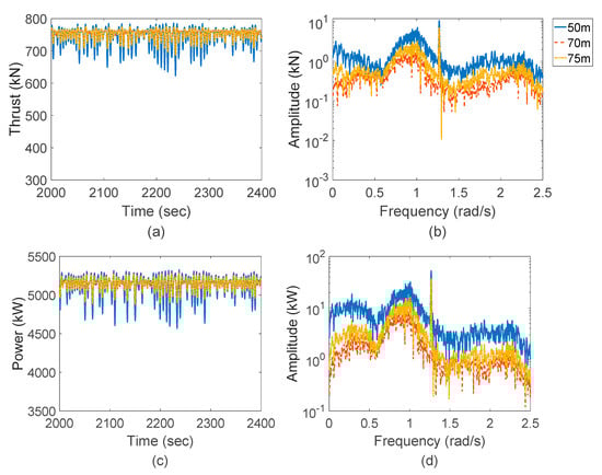
Figure 8.
Aerodynamic performance of the rotor. (a) Time histories of thrust on the rotor (b) Response spectra of thrust on the rotor (c) Time histories of output power (d) Response spectra of output power.
Based on the response spectra in Figure 8b,d, it can be seen that the response spectrum of thrust and power generation has similar peaks with the pitch response spectrum. Similarly, these aerodynamic responses of the 50 m depth AOWT are also larger than the other AOWTs. Furthermore, the response spectrum of power generation has a similar shape to the thrust spectrum. This is because power generation depends on the torque acting on the rotor. Both torque and thrust are the corresponding aerodynamic load components in the horizontal and vertical plane of the rotor. The results show that the peak value and variation trend of these two components have consistency to a certain extent.
4.2.3. Tension on Hinged Joint
In order to investigate the dynamic performance of the hinged joint, tensions acting on it must be considered in the simulation. Figure 9 shows the time histories and response spectra of tensions on the hinged joint.
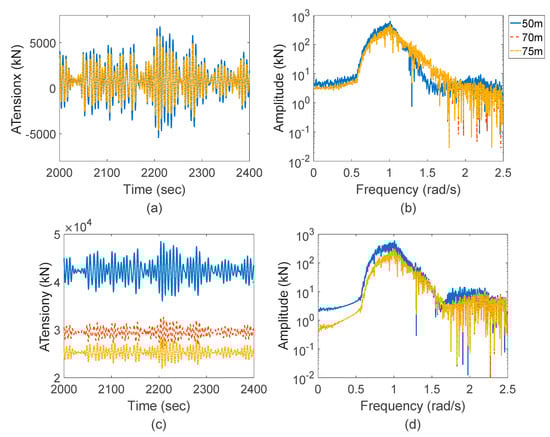
Figure 9.
Tensions on the hinged joint. (a) Time histories of x-direction Tension on the articulated joint (b) Response spectra of x-direction Tension on the articulated joint (c) Time histories of y-direction Tension on the articulated joint (d) Response spectra of y-direction Tension on the articulated joint.
From the results in Figure 6e,f and Figure 9a,c, it can be obtained that under the same condition, the average value of X-direction tensions remains at the same level among the three AOWTs. However, the oscillation of the 50 m depth AOWT is still slightly larger than the other ones. This phenomenon is similar to the pitch motion and aerodynamic performance. Therefore, it could be recognized as the effect of damping.
Besides, an obvious difference could be observed in the tension in the Y-direction. In other words, the water depth may significantly influence the vertical tensions on the hinge. On one hand, according to the time histories in Figure 9c, the average vertical tensions of the 70 m depth and 75 m depth AOWTs are about 70% and 60% of that of the 50 m depth AOWT, respectively. This phenomenon is basically caused by the different initial tensions on the hinges as Table 2 shows. On the other hand, the response spectra in Figure 9d show that the oscillations in vertical tension are dominated by the wave-frequency component. Nevertheless, both low-frequency and wave-frequency responses of hinge tension in the 50 m depth AOWT are amplified due to the lower damping.
5. Conclusions and Discussions
A new kind of AOWT is proposed for the transitional water depth area. To investigate the influence of water depth on the dynamic responses of this articulated system, three different AOWTs are adopted to perform the simulation under the corresponding rated operational condition. All of them are based on optimized works to reach the best balance between safety and economic features.
Firstly, to study the wave–body interaction, the hydrodynamic analysis was performed in the frequency domain. The pitch natural frequency of the structure avoids the wave frequency, as well as the 1P and 3P load frequencies, and there are few resonance motions during the normal operational condition. Furthermore, the aero-hydro coupling analysis model is established in the time domain, as well as an in-house numerical code. Considering aerodynamic, hydrodynamic, and dynamics theories, a single-degree-of-freedom rigid body analysis model of the articulated wind turbine was established based on the Cummins Equation and convolutional method. Results show that it has great motion performance and meets the requirement of power generation. The horizontal tension of the hinged joint is dominated by the wave load, and the axial tension is dominated by the residual buoyancy.
Generally, the water depth has a significant influence on the dynamic performance of AOWTs. On the one hand, the wave load of the 50 m depth foundation is larger than the other two foundations. This is mainly caused by the larger diameter tank near the free surface, which is designed to provide enough buoyancy and restoring moment. On the other hand, for the dynamic responses of a 50 m depth AOWT, including foundation pitch, aerodynamic loads, output power, and hinged tensions, all oscillate more severely under the normal operational condition. In other words, it is much more challenging to control the motion and corresponding dynamic response of AOWT in the shallower water area.
However, it is necessary to point out that those articulated offshore wind turbines are designed conceptually and initially in the current work. There still exist some potential issues to be studied in the future. Firstly, in the present study, the rated operational sea state is adopted to show the dynamic responses of AOWT under different water depths. However, the real sea scenarios are more complex than this one. Specifically, for a practical wind engineering project, more overall calculations based on the other scenarios should be investigated, especially sea conditions corresponding to the cut-in and cut-out wind speed. Besides, in order to ensure the safety of the structure design, the influence of the survival sea condition and turbulent wind flow [51] also need to be reflected in following research. On the other hand, collinear-direction wind and wave are adopted in present simulations. However, especially during typhoon, storm, tsunami, or other catastrophic instances in the oceans [52], some scenarios exist in which the wind and waves are in non-collinear or even opposite directions. It is worth being investigated in future works.
Besides, according to the simulated results, we see that the output power is maintained at about 5 MW under the normal operation sea state, similar to the OC3 Hywind Spar or OC4 DeepCwind semisubmersible FOWTs [53,54]. However, the foundation motion can hardly be compared with the motions of the FOWTs directly, because of the different water depths. In the next stage, we would make a comparison of the dynamic responses between AOWT and FOWT in the same water depth range.
On the other hand, it is an interesting topic to analyze the dynamic behavior of AOWT in arctic areas. In the present work, our designed AOWTs are aiming at the tropical area in the South China Sea, where the air temperature can hardly reach the level of the arctic areas. However, when wind turbines operate in the cold area, a considerable increment of the air density will occur [55]. It may lead to amplified aerodynamic loads and output power [56]. Hereby, the seasonal correction of the wind power due to the air density [57] will be taken into consideration in our future work. We may firstly conduct an optimization of the AOWT in order to be suitable for bearing ice and other extreme loads in the arctic areas. Furthermore, we would like to take the air density effect into consideration when we perform the aerodynamic simulations.
At present, we are planning to conduct a series of experimental tests to investigate the hydrodynamic and structural dynamic performance. We will directly validate our numerical results with model test ones in future works. In the model test, a 1/50 scale of the AOWT will be considered under different conditions. Moreover, the design of the specified hinged joint, a detailed structural design, and a cost analysis of the system will also be done in the future. Furthermore, we seek to find a substitute approach to simulate the articulated joint in other numerical codes. A potential way is to use a short stiff mooring line to model the ball joint, and this trial is performed in FAST.
Another potential issue is the flexibility of the upper structures, including blades and tower, is not included in this paper. These works will be done in the following research through the research methods by Chen [58], who proposed a nonlinear rigid-flexible coupled dynamic model of floating offshore wind turbines. Moreover, in the present study, we consider a single-degree-of-freedom rigid body analysis model. To be more precise, these simulations should be performed by the rigid-flexible coupled multi-body analysis model. In future work, a fully coupled time-domain code and a rigid-flexible coupled multi-body analysis model will be built for further study on the dynamic characteristics of AOWTs.
Author Contributions
Conceptualization, P.Z., Y.L. and Y.T.; methodology, Y.L.; software, P.Z. and Y.L.; validation, Y.L. and J.G.; formal analysis, P.Z.; writing—original draft preparation, P.Z.; writing—review and editing, Y.L., J.G., Z.H. and R.Z.; supervision, S.Y. and Y.T.; project administration, Y.T.; funding acquisition, Y.L. and Y.T. All authors have read and agreed to the published version of the manuscript.
Funding
This research was funded by Nation Natural Science Foundation of China, grant numbers: 51879188 and 51779109; the Natural Science Foundation of Jiangsu Province, grant numbers: BK20171306; the Project funded by China Postdoctoral Science Foundation: 2019M651042 and the Innovative Foundation of Tianjin University: 2020XZS-0004.
Acknowledgments
Supports from State Key Laboratory of Hydraulic Engineering Simulation and Safety and Tianjin Key Laboratory of Port and Ocean Engineering are gratefully acknowledged.
Conflicts of Interest
The authors declare no conflict of interest. The funders had no role in the design of the study; in the collection, analyses, or interpretation of data; in the writing of the manuscript, or in the decision to publish the results.
Nomenclature
| (x, y) | a Cartesian coordinate system with its origin at the hinged joint |
| pitch angle of the AOWT [rad] | |
| pitch angular speed of the AOWT [rad/s] | |
| pitch angular acceleration of the AOWT [rad/s2] | |
| I | system moment of inertia [kg·m2] |
| IA (ω) | additional moment of inertia [kg·m2] |
| Iinf | additional moment of inertia when the frequency approaches infinite [kg·m2] |
| ω | wave frequency [rad/s] |
| β | phase angle [rad] |
| C1 (ω) | radiation damping coefficient [N·m / rad·s−1] |
| C2 | viscous friction damping coefficient [N·m / rad·s−1] |
| K | restoring stiffness of the system [N·m /rad] |
| F (ω, β) | wave force in frequency domain [N] |
| h (t) | retardation function |
| D | damping coefficient [N·m / rad·s−1] |
| Q | external environmental loads [N] |
| Mfr | friction damping moment [N·m] |
| μ | friction coefficient (μ = 0.1) |
| N | normal force [N] |
| R | radius of the spherical articulated joint (R = 1.5, m) |
| unit vectors in the same direction as angular velocity vectors | |
| Mvi | overall damping moment [N·m] |
| Cvi | dimensionless damping ratio (Cvi = 0.055) |
| MR | restoring moment [N·m] |
| Fbuoy | buoyancy of the articulated foundation [N] |
| lb | moment arm of buoyancy to the hinged joint [m] |
| M | total mass of the whole structure [kg] |
| lg | moment arm of gravity to the hinged joint [m] |
| g | acceleration of gravity (9.81, m/s2) |
| dT | axial thrust on blade element [N] |
| dM | torque on blade element [N·m] |
| ρ | air density [kg/m3] |
| V | resultant wind speed on the blade [m/s] |
| B | number of blades |
| c | chord length of the blade element [m] |
| Cl | lift coefficient of the blade element |
| Cd | drag coefficient of the blade element |
| φ | inflow angle [rad] |
| r | distance from the local element to the hub [m] |
| dr | length of the blade element [m] |
| F | Prandtl loss factor |
| Ftip | Prandtl tip-loss factor |
| Fhub | Prandtl hub-loss factor |
| Fwind | wind load on the tower [N] |
| n | total number of tower components |
| Ch | height coefficient (Ch = 1.0) |
| Cs | shape coefficient (Cs = 1.0) |
| Ai(α) | projection area of the corresponding part when the wind direction angle is α [m2] |
| Vri | relative wind speed corresponding to different heights [m/s] |
| Mw | total wind moment [N·m] |
| lR | moment arm of aerodynamic thrust to the hinged joint [m] |
| lc | moment arm of wind pressure on tower to the hinged joint [m] |
| Fwave | wave force [N] |
| aj | wave amplitude corresponding to the j-th wave component [m] |
| ωj | circular wave frequency corresponding to the j-th wave component [rad/s] |
| φj | initial phase angle corresponding to the j-th wave component [rad] |
| F1 (ω) | hydrodynamic transfer function |
| Fcur | current load [N] |
| CD | drag coefficient on foundation (CD = 0.7) |
| ρw | seawater density [kg/m3] |
| A | projection area of the component perpendicular to the velocity of current [m2] |
| Vcur | relative velocity of current [m/s] |
References
- Stock-Williams, C.; Swamy, S.K. Automated daily maintenance planning for offshore wind farms. Renew. Energy 2019, 133, 1393–1403. [Google Scholar] [CrossRef]
- Gonzalez-Rodriguez, A.G. Review of offshore wind farm cost components. Energy Sustain. Dev. 2017, 37, 10–19. [Google Scholar] [CrossRef]
- Lacal-Arántegui, R.; Yusta, J.M.; Domínguez-Navarro, J.A. Offshore wind installation: Analyzing the evidence behind improvements in installation time. Renew. Sustain. Energy Rev. 2018, 92, 133–145. [Google Scholar] [CrossRef]
- Whiteman, A.; Esparrago, J.; Elsayed, S. Renewable Energy Statistics 2018; International Renewable Energy Agency: Abu Dhabi, UAE, 2018. [Google Scholar]
- Wu, X.; Hu, Y.; Li, Y.; Yang, J.; Duan, L.; Wang, T.; Borthwick, A. Foundations of offshore wind turbines: A review. Renew. Sustain. Energy Rev. 2019, 104, 379–393. [Google Scholar] [CrossRef]
- Hsu, W.; Thiagarajan, K.P.; Manuel, L. Extreme mooring tensions due to snap loads on a floating offshore wind turbine system. Mar. Struct. 2017, 55, 182–199. [Google Scholar] [CrossRef]
- Li, L.; Liu, Y.; Yuan, Z.; Gao, Y. Dynamic and structural performances of offshore floating wind turbines in turbulent wind flow. Ocean Eng. 2019, 179, 92–103. [Google Scholar] [CrossRef]
- Salehyar, S.; Li, Y.; Zhu, Q. Fully-coupled time-domain simulations of the response of a floating wind turbine to non-periodic disturbances. Renew. Energy 2017, 111, 214–226. [Google Scholar] [CrossRef]
- Oguz, E.; Clelland, D.; Day, A.H.; Incecik, A.; López, J.A.; Sánchez, G.; Almeria, G.G. Experimental and numerical analysis of a TLP floating offshore wind turbine. Ocean Eng. 2018, 147, 591–605. [Google Scholar] [CrossRef]
- Chen, J.; Hu, Z.; Liu, G.; Wan, D. Coupled aero-hydro-servo-elastic methods for floating wind turbines. Renew. Energy 2019, 130, 139–153. [Google Scholar] [CrossRef]
- Lin, Z.; Liu, X. Assessment of Wind Turbine Aero-Hydro-Servo-Elastic Modelling on the Effects of Mooring Line Tension via Deep Learning. Energies 2020, 13, 2264. [Google Scholar] [CrossRef]
- Le, C.; Li, Y.; Ding, H. Study on the Coupled Dynamic Responses of a Submerged Floating Wind Turbine under Different Mooring Conditions. Energies 2019, 12, 418. [Google Scholar] [CrossRef]
- Karimirad, M.; Michailides, C. Dynamic analysis of a brakeless semisubmersible offshore wind turbine in operational conditions. Energy Procedia 2015, 80, 21–29. [Google Scholar] [CrossRef][Green Version]
- Jang, H.K.; Park, S.; Kim, M.H.; Kim, K.H.; Hong, K. Effects of heave plates on the global performance of a multi-unit floating offshore wind turbine. Renew. Energy 2019, 134, 526–537. [Google Scholar] [CrossRef]
- Sauder, T.; Chabaud, V.; Thys, M. Real-Time Hybrid Model Testing of a Brakeless Semi-Submersible Wind Turbine: Part I—The Hybrid Approach. In Proceedings of the ASME 2016 35th International Conference on Ocean, Offshore and Arctic Engineering, Busan, Korea, 19–24 June 2016; American Society of Mechanical Engineers: New York, NY, USA, 2016. [Google Scholar]
- Melis, C.; Caille, F.; Perdrizet, T.; Poirette, Y.; Bozonnet, P. A Novel Tension-Leg Application for Floating Offshore Wind: Targeting Lower Nacelle Motions. In Proceedings of the ASME 2016 35th International Conference on Ocean, Offshore and Arctic Engineering, Busan, Korea, 19–24 June 2016; American Society of Mechanical Engineers: New York, NY, USA, 2016. [Google Scholar]
- De Guzmán, S.; Marón, D.; Bueno, P.; Taboada, M.; Moreu, M. A Reduced Draft Spar Concept for Large Offshore Wind Turbines. In Proceedings of the ASME 2018 37th International Conference on Ocean, Offshore and Arctic Engineering, Madrid, Spain, 17–22 June 2018; American Society of Mechanical Engineers: New York, NY, USA, 2018. [Google Scholar]
- Nagamani, K.; Ganapathy, C. Finite element analysis of nonlinear dynamic response of articulated towers. Comput. Struct. 1996, 59, 213–223. [Google Scholar] [CrossRef]
- Nagamani, K.; Ganapathy, C. The dynamic response of a three-leg articulated tower. Ocean Eng. 2000, 27, 1455–1471. [Google Scholar] [CrossRef]
- Pezo, E.; Gonçalves, P.; Roehl, D. Non-Linear Finite Element Analysis of the Dynamics of a Slender Cable Stayed Tower. MATEC Web Conf. 2018, 148, 03001. [Google Scholar] [CrossRef][Green Version]
- Gavassoni, E.; Gonçalves, P.B.; de Mesquita Roehl, D. Nonlinear vibration modes of an offshore articulated tower. Ocean Eng. 2015, 109, 226–242. [Google Scholar] [CrossRef]
- Zaheer, M.M.; Islam, N. Dynamic response of articulated towers under correlated wind and waves. Ocean Eng. 2017, 132, 114–125. [Google Scholar] [CrossRef]
- Javed, S.Y. Near Fault Effect on the Response of Single Hinged Compliant Offshore Tower. MATEC Web Conf. 2018, 203, 01015. [Google Scholar] [CrossRef][Green Version]
- Wu, H.T.; Zhang, L.; Zhao, J.; Ye, X.R. Primary Design and Dynamic Analysis of an Articulated Floating Offshore Wind Turbine. In Advanced Materials Research, Proceedings of the International Conference on Energy, Environment and Sustainable Development (ICEESD 2011), Shanghai, China, 21–23 October 2011; Trans. Tech. Publications: Zurich, Switzerland, 2012; Volume 347, pp. 2191–2194. Available online: http://fbic30fd8c346ef34d67903a5b6d8ea5d318snc9u5c5wfv566qpk.fiac.eds.tju.edu.cn/10.4028/www.scientific.net/AMR.347-353.2191 (accessed on 1 May 2020).
- Philip, V.; Joseph, A.; Joy, C.M. Three legged articulated support for 5 MW offshore wind turbine. Aquat. Procedia 2015, 4, 500–507. [Google Scholar] [CrossRef]
- Joy, C.M.; Joseph, A.; Mangal, L. Experimental investigation on the dynamic response of a three-legged articulated type offshore wind tower. In Proceedings of the ASME 2016 35th International Conference on Ocean, Offshore and Arctic Engineering, Busan, Korea, 19–24 June 2016; American Society of Mechanical Engineers: New York, NY, USA, 2016; p. V001T01A009. [Google Scholar]
- Navin, S.S.; Philip, V. Fatigue Analysis of Articulated Support for Offshore Wind Turbine. Int. Res. J. Eng. Technol. 2016, 4, 2266–2271. [Google Scholar]
- Casale, C.; Lembo, E.; Serri, L.; Viani, S. Preliminary design of a floating wind turbine support structure and relevant system cost assessment. Wind Eng. 2010, 34, 29–50. [Google Scholar] [CrossRef]
- Zhou, M.H. Analysis of Nonlinear Dynamics Response of an Articulated Tower Platform. Master’s Thesis, Tianjin University, Tianjin, China, 2005. (In Chinese). [Google Scholar]
- Li, Y.; Zhu, Q.; Liu, L.; Tang, Y. Transient response of a SPAR-type floating offshore wind turbine with fractured mooring lines. Renew. Energy 2018, 122, 576–588. [Google Scholar] [CrossRef]
- Li, Y.; Liu, Z.; Tang, Y.; Zhu, X.; Zhang, R. Dynamic Response of a Conceptual Designed Articulated Offshore Wind Turbine. In Proceedings of the ASME 2019 38th International Conference on Ocean, Offshore and Arctic Engineering, Glasgow, Scotland, UK, 9–14 June 2019; Volume 10: Ocean Renewable Energy. ASME: New York, NY, USA, 2019; p. V010T09A050. [Google Scholar]
- Xie, W.; Tang, Y.; Zhou, M. Nonlinear dynamic characteristic analysis of articulated tower platform in the deep water. Eng. Mech. 2006, 23, 36–41+119. (In Chinese) [Google Scholar]
- DNV GL. Position Mooring. Offshore Standards, DNVGL-OS-E301. Edition July 2018. Available online: http://rules.dnvgl.com/docs/pdf/dnvgl/os/2018-07/dnvgl-os-e301.pdf (accessed on 1 May 2020).
- Tao, L.B. Viscous damping of TLP and Spar in deep water. Ship Build. China 2006, 2, 21–27. (In Chinese) [Google Scholar]
- Zhang, P.; Yang, S.; Li, Y.; Tang, Y. Coupled Response Analysis of an Offshore Articulated Wind Turbine under Different Environmental Loads. In Proceedings of the 11th International Workshop on Ship and Marine Hydrodynamics, Hamburg, Germany, 22–25 September 2019. [Google Scholar]
- Moriarty, P.J.; Hansen, A.C. AeroDyn Theory Manual (No. NREL/TP-500-36881); National Renewable Energy Lab.: Golden, CO, USA, 2005.
- Lerch, M.; De-Prada-Gil, M.; Molins, C. The influence of different wind and wave conditions on the energy yield and downtime of a Spar-buoy floating wind turbine. Renew. Energy 2019, 136, 1–14. [Google Scholar] [CrossRef]
- Li, Y.; Liu, L.; Zhu, Q.; Guo, Y.; Hu, Z.; Tang, Y. Influence of vortex-induced loads on the motion of SPAR-type wind turbine: A coupled aero-hydro-vortex-mooring investigation. J. Offshore Mech. Arct. Eng. 2018, 140, 051903. [Google Scholar] [CrossRef]
- Li, L.; Hu, Z.; Wang, J.; Ma, Y. Development and Validation of an Aero-hydro Simulation Code for Offshore Floating Wind Turbine. J. Ocean Wind Energy 2015, 2, 1–11. [Google Scholar]
- Allen, C.K.; Goupee, A.J.; Viselli, A.M.; Dagher, H.J. Experimental Validation of a Spectral-Based Structural Analysis Model Implemented in the Design of the VolturnUS 6MW Floating Offshore Wind Turbine. In Proceedings of the 27th International Ocean and Polar Engineering Conference, San Francisco, CA, USA, 25–30 June 2017. [Google Scholar]
- Qu, X.; Li, Y.; Tang, Y.; Hu, Z.; Zhang, P.; Yin, T. Dynamic response of spar-type floating offshore wind turbine in freak wave considering the wave-current interaction effect. Appl. Ocean Res. 2020, 100, 102178. [Google Scholar] [CrossRef]
- Li, Y.; Tang, Y.; Zhu, Q.; Qu, X.; Wang, B.; Zhang, R. Effects of second-order wave forces and aerodynamic forces on dynamic responses of a TLP-type floating offshore wind turbine considering the set-down motion. J. Renew. Sustain. Energy 2017, 9, 063302. [Google Scholar] [CrossRef]
- Li, Y.; Qu, X.; Liu, L.; Xie, P.; Yin, T.; Tang, Y. A Numerical Prediction on the Transient Response of a Spar-type Floating Offshore Wind Turbine in Freak Waves. ASME J. Offshore Mech. Arct. Eng. 2020. [Google Scholar] [CrossRef]
- China Classification Society. Offshore Mobile Platform Classification Guidelines; Communications Press: Beijing, China, 2005. (In Chinese) [Google Scholar]
- China Classification Society. Offshore Wind Turbine Classification Guidelines; Beijing, China Classification Society: Beijing, China, 2012. (In Chinese) [Google Scholar]
- International Electrotechnical Commission. Wind Energy Generation Systems. Part 3–1: Design Requirements for Fixed Offshore Wind Turbines; International Electrotechnical Commission: Geneva, Switzerland, April 2019; Available online: http://www.doc88.com/p-1931753549706.html (accessed on 1 May 2020).
- Faltinsen, O. Sea Loads on Ships and Offshore Structures; Cambridge University Press: Cambridge, UK, 1993. [Google Scholar]
- Kirk, C.L.; Jain R, K. Response of articulated towers to waves and current. Soc. Pet. Eng. J. 1978, 18, 283–290. [Google Scholar] [CrossRef]
- Frigo, M.; Johnson, S.G. FFTW: An adaptive software architecture for the FFT. In Proceedings of the 1998 IEEE International Conference on Acoustics, Speech and Signal Processing, ICASSP’98, Seattle, WA, USA, 12–15 May 1998; Volume 3, pp. 1381–1384. [Google Scholar]
- Pires, I.M.; Garcia, N.M.; Pombo, N.; Flórez-Revuelta, F.; Spinsante, S. Approach for the Development of a Framework for the Identification of Activities of Daily Living Using Sensors in Mobile Devices. Sensors 2018, 18, 640. [Google Scholar] [CrossRef] [PubMed]
- Qu, X.; Li, Y.; Tang, Y.; Chai, W.; Gao, Z. Comparative study of short-term extreme responses and fatigue damages of a floating wind turbine using two different blade models. Appl. Ocean Res. 2020, 97, 102088. [Google Scholar] [CrossRef]
- Wu, L.; Shao, M.; Sahlée, E. Impact of Air–Wave–Sea Coupling on the Simulation of Offshore Wind and Wave Energy Potentials. Atmosphere 2020, 11, 327. [Google Scholar] [CrossRef]
- Ahn, H.J.; Shin, H. Model test and numerical simulation of OC3 spar type floating offshore wind turbine. Int. J. Nav. Arch. Ocean Eng. 2019, 11, 1–10. [Google Scholar] [CrossRef]
- Urban, A.M.; Guanche, R. Wind turbine aerodynamics scale-modeling for floating offshore wind platform testing. J. Wind Eng. Ind. Aerodyn. 2019, 186, 49–57. [Google Scholar] [CrossRef]
- Ulazia, A.; Gonzalez-Rojí, S.J.; Ibarra-Berastegi, G.; Carreno-Madinabeitia, S.; Sáenz, J.; Nafarrate, A. Seasonal Air Density Variations over the East of Scotland and The Consequences for Offshore Wind Energy. In Proceedings of the 2018 7th International Conference on Renewable Energy Research and Applications (ICRERA), Paris, France, 14–17 October 2018; pp. 261–265. [Google Scholar] [CrossRef]
- Ulazia, A.; Ibarra-Berastegi, G.; Sáenz, J.; Carreno-Madinabeitia, S.; González-Rojí, S.J. Seasonal Correction of Offshore Wind Energy Potential due to Air Density: Case of the Iberian Peninsula. Sustainability 2019, 11, 3648. [Google Scholar] [CrossRef]
- Ulazia, A.; Sáenz, J.; Ibarra-Berastegi, G.; González-Rojí, S.J.; Carreno-Madinabeitia, S. Global estimations of wind energy potential considering seasonal air density changes. Energy 2019, 187, 115938. [Google Scholar] [CrossRef]
- Chen, J.H.; Hu, Z.Q.; Liu, G.L.; Wan, D.C. Study on Rigid-Flexible Coupling Effects of Floating Offshore Wind Turbines. China Ocean Eng. 2019, 33, 1–13. [Google Scholar] [CrossRef]
© 2020 by the authors. Licensee MDPI, Basel, Switzerland. This article is an open access article distributed under the terms and conditions of the Creative Commons Attribution (CC BY) license (http://creativecommons.org/licenses/by/4.0/).