Abstract
The cruising distance of the range extended electric vehicle (REEV) can be further extended using a range extender, which consists of an engine and a generator, i.e., a genset. An adaptive power management strategy (PMS) based on the equivalent fuel consumption minimization strategy (ECMS) is proposed for the REEV in this paper. The desired trajectory of the state of charge (SOC) is designed based on the energy-to-distance ratio, which is defined as the difference between the initial SOC and the minimum allowable SOC divided by the remaining travel distance, for discharging the battery. A self-organizing fuzzy controller (SOFC) with SOC feedback is utilized to modify the equivalence factor, which is defined as the fuel consumption rate per unit of electric power, for tracking the desired SOC trajectory. An instantaneous cost function, that consists of the fuel consumption rate of the genset and the equivalent fuel consumption rate of the battery, is minimized to find the optimum power distribution for the genset and the battery. Dynamic programming, which is a global minimization method, is employed to obtain the performance upper bound for the target REEV. Simulation results show that the proposed algorithm is adaptive for different driving cycles and can effectively increase the fuel economy of the thermostat control strategy (TCS) by 11.1% to 16%. The proposed algorithm can also reduce average charging/discharging powers and low SOC operations for possibly extending the battery life and increasing the battery efficiency, respectively. An experiment of the prototype REEV on a chassis dynamometer is set up with the proposed algorithm implemented on a real-time controller. Experiment results show that the proposed algorithm can increase the fuel economy of the TCS by 7.8% for the tested driving cycle. In addition, the proposed algorithm can reduce the average charge/discharge powers of TCS by 7.9% and 11.7%, respectively.
1. Introduction
Due to the deteriorating global warming problem and more and more rigorous emission laws, major automotive makers are developing new energy vehicles, like electric vehicles (EVs), hybrid electric vehicles (HEVs), and plug-in hybrid electric vehicles (PHEVs) [1]. The EVs are propelled by one or more traction motors (TMs) with the battery as the main energy source. The HEVs are propelled by an engine and one or more TMs with the gasoline or diesel fuel as the main energy source. The battery is used as the auxiliary energy buffer. The PHEVs can be viewed as the HEVs with an additional plug-in charging capability such that the battery can be recharged from the external electric power source. However, the cruising distance of EV is often restricted due to the inadequate gravimetric energy density which is defined as the battery capacity per unit mass. Although increasing the battery capacity can increase the cruising distance, it makes the vehicle heavier and more expensive. Range extended electric vehicles (REEVs) [2] can overcome the limitations of current EVs by use of a range extender, which consists of an engine and a generator, i.e., a genset. REEV can be viewed as a series HEV with plug-in ability to recharge the battery [3]. Both the genset and the battery can provide electric power for the TM. The genset can charge the battery when necessary.
The most important function of the power management strategy (PMS) for REEV is to determine the power split ratio between the genset and the battery such that the fuel economy is optimized for various driving conditions. The PMS can be classified into four types as shown in Figure 1. Type I is the rule-based control. The thermostat control strategy (TCS) [4] uses the battery as the major power source and operates the vehicle in the EV mode when the state of charge (SOC) is larger than the lower bound. When the SOC is less than or equal to the lower bound, the genset begins operating at the most efficient working point to provide electric power until the SOC reaches the upper bound. It is viewed as the charge sustaining (CS) mode to keep the SOC inside the allowed range [5,6]. The power follower control strategy (PFCS) [7,8,9] uses the genset as the major power source in the most-efficient operating range. If the driver demands more than the maximum genset power, the battery is used to provide additional power when the SOC is in the allowed range. If the driver demands less than the minimum genset power and the SOC is in the allowed range, the genset is turned off and the battery is used as the major power source. If the SOC is less than or equal to the lower bound, the genset outputs the maximum power. The difference between the genset power and the driver’s power demand is used to charge the battery.
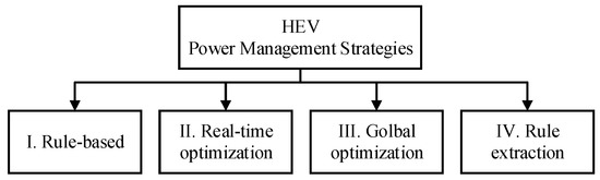
Figure 1.
Classification of power management strategies.
Type II is the equivalent fuel consumption minimization strategy (ECMS), which is an optimization-based approach [10,11,12,13]. The equivalence factor which is defined as the fuel consumption rate per unit electric power is used to transform the battery power into the equivalent fuel consumption rate and is commonly designed as a predetermined function of SOC. An instantaneous cost function, that consists of the fuel consumption rate of the genset and the equivalent fuel consumption rate of the battery, is minimized to find the optimum power distribution for the genset and the battery. However, the predetermined function might not be appropriate for all driving cycles. The ECMS is utilized to minimize the fuel consumption rate based on the Pontryagin’s minimum principle (PMP) [14,15] which provides a set of necessary conditions to find the optimal solution. In order to reduce the computational load of PMP, Hou et al. [16] proposed an optimal energy management strategy based on the approximate PMP, which can be implemented in real-time. Musardo et al. [17] proposed an adaptive ECMS with an online adaptive algorithm, which can estimate the optimal equivalence factor for the forecast driving cycle. The ECMS can then be used to resolve the power distribution for the genset and the battery according to the updated equivalence factor.
Type III is dynamic programming (DP) [18,19,20], which is a global minimization method over a time horizon. DP is frequently used to solve the energy management problems of HEVs [21,22,23] and find the performance upper bound for benchmarking control strategies for a specific driving cycle. Patil et al. [24] employed DP to compare two supervisory control strategies for a series PHEV with different formulations of the cost functions. One optimal strategy has no restrictions on the fuel usage and the other, constrained optimal strategy, is allowed to use fuel only after the SOC is depleted below a certain threshold. For most cases, the optimum control strategy is better than the constrained control strategy. The constrained control strategy only performs better for extremely low gasoline price and short travel distance.
Type IV is the rule extraction method, which is obtained by analyzing the optimum control policy from DP [25]. Chen et al. [26] designed a rule-based multi-mode switch strategy for REEV. The strategy employs a driving pattern recognition method to change between different management rule sets, which are extracted from the DP outcomes using representative driving patterns. Zhang et al. [27] proposed an adaptive energy management strategy. A fuzzy logic controller is employed for classifying typical driving cycles into different driving patterns. Three rule-based control strategies for these driving patterns have been developed by analyzing the optimum control policy obtained from DP. Driving pattern recognition is employed to select the control strategies for the corresponding driving patterns. Pei et al. [28] used the optimal equivalence factor obtained from DP as a reference value. An adaptive law is utilized to modify the reference equivalence factor of ECMS control strategy with a correction term based on the difference between the moving average of SOC and the reference SOC.
Among above PMSs, Type I is easy to design and implement due to the rule-based structure. However, its performance is often limited and sub-optimal. Type III can obtain the optimum control policies via global optimization. However, it can’t be implemented in real-time because of the heavy computation load and the unavailable future driving cycles. Type IV can be implemented in real-time by extracting rules from the optimum control policies resulting from Type III. However, the future driving cycles are still unavailable. Patten recognition is often needed to switch between different sets of rules to obtain near-optimal performance. Type II can be implemented in real-time to obtain the near-optimal performance. In order to be adaptive to different driving cycles, the velocity predictor is used to foresee the change of the driving behaviors and modify the equivalence factor of ECMS accordingly. However, the velocity predictor is often based on the historical traffic flow data and cannot accurately represent the future unknown driving cycles. In order to solve this problem, an adaptive PMS, which only requires the measurements of the battery SOC, vehicle velocity and driver’s power request, is proposed in this paper.
The proposed adaptive PMS for the REEV, which is based on the ECMS algorithm, is an extension of the previous work published in [29] with additional DP for the benchmark, more simulation studies, and experiments of the target REEV. The key to ECMS implementation is to properly identify the equivalence factor. In the proposed adaptive PMS, the equivalence factor of battery power consumption is adaptively modified online by a self-organizing fuzzy controller (SOFC) based on the SOC feedback for tracking the desired SOC trajectory. An instantaneous cost function, that consists of the fuel consumption rate of the genset and the equivalent fuel consumption rate of the battery power, is minimized using ECMS to find the optimum power distributions for the genset and the battery. DP is employed to obtain the performance upper bound for the target REEV. Three standard driving cycles—New European Driving Cycle (NEDC), Federal Test Procedure (FTP), and Urban Dynamometer Driving Schedule (UDDS)—are used to evaluate the fuel economy and the average charging/discharging power via simulation studies. The simulation results of the conventional TCS are used as the performance lower bound. Experiments of the target REEV on a chassis dynamometer are used to evaluate the proposed adaptive PMS for four NEDC driving cycles.
The remainder of the paper is organized as follows: in Section 2, the configuration of the REEV is introduced. The DP algorithm is described in Section 3. The proposed adaptive PMS is shown in Section 4. Simulation and experimental results are discussed in Section 5. Finally, conclusions are presented in Section 6.
2. Powertrain Modeling
The powertrain configuration of the target REEV is shown in Figure 2. The output power of the genset can be divided into to charge the battery and to drive the TM. is the battery power; and are the output torques of the TM and the final drive, respectively. The REEV is an electric multi-purpose vehicle (MPV) with a 40 kW engine, a 25 kW generator, a 150 kW traction motor (TM), and a 16 kWh lithium-ion battery pack. The specifications of the REEV are summarized in Table 1. During braking, the total required braking torque consists of the regenerative braking from the TM and the friction braking from the hydraulic braking. Brake-by-wire capabilities are required for both braking systems [30]. Since the hydraulic braking system of the target REEV does not have the brake-by-wire capability, the regenerative braking is not used for the target REEV. The simulation models, with some component models adapted from [31], are described as follows.
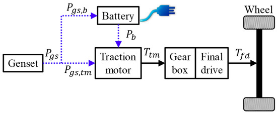
Figure 2.
Configuration of the REEV.

Table 1.
REEV specifications.
The efficiency map of the TM is a function of the motor speed and torque as shown in Figure 3. Since the electric dynamics are relatively fast compared to the mechanical dynamics, the motor torque can be described by a first order dynamics as shown below:
where is the motor torque requested by the driver; is the maximum allowable motor torque restricted by the maximum torque curve; is the maximum allowable motor torque restricted by the maximum output power of the battery; is the time constant of the motor.
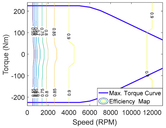
Figure 3.
Efficiency map of the traction motor.
The engine and the generator of the genset are coaxial. The rotational dynamics of the genset are described by the following first-order differential equation:
where and are rotational inertias of the engine and the generator, respectively; is the engine torque which is a function of the engine speed and the throttle angle ; is the generator torque. Because engine parameters belong to the manufacturer’s confidential information, the brake specific fuel consumption (BSFC) map of the engine model is normalized by the minimum BSFC and presented as a BSFC ratio map in this paper. The BSFC ratio map is represented by a function of and as shown in Figure 4. The actual BSFC is equal to the BSFC ratio multiplied by the minimum BSFC.
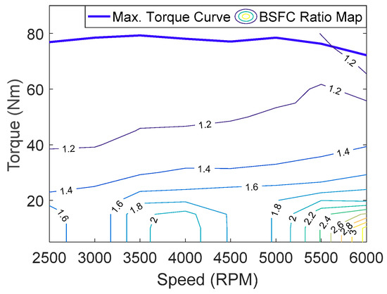
Figure 4.
BSFC ratio map of the engine.
The generator efficiency map is represented by a function of and in Figure 5. Similar to the motor torque dynamics in Equation (1), the generator torque can be described by a first order dynamics as shown below:
where is the requested generator torque; and are the maximum allowable torques limited by the maximum torque curves of the engine and the generator, respectively; is the time constant of the genset.
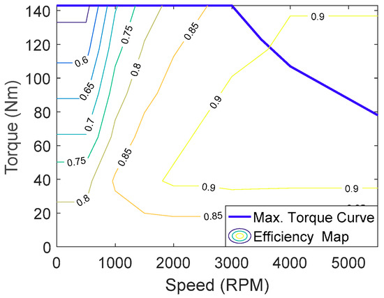
Figure 5.
Efficiency map of the generator.
The reduction gearbox with a fixed gear ratio is configured between the TM and final drive. The output torque of the final drive can be expressed as follows:
where is the gear ratio; is the efficiency; the subscripts and denote the reduction gear and final drive, respectively. The wheel dynamics can be expressed as follows:
where is the wheel speed; is the lumped rotational inertia of the wheel with the consideration of the rotational inertia of the final drive; is the braking torque; is the rolling radius of the wheel; is the rotational damping coefficient; is the longitudinal tire force, which can be expressed as follows:
where is the vertical tire force; is the road friction coefficient, which is a function of the tire slip ratio . can be expressed as follows:
where is the longitudinal vehicle speed.
The battery pack consists of 2208 cells. 96 cells are connected in series to form a module, and 23 modules are connected in parallel. The resistance capacitance (RC) battery model in ADVISOR [32], which consists of two capacitors and three resistors as shown in Figure 6, is used to describe the battery dynamics as follows:
where is the bulk capacitor; is the surface capacitor; is the voltage across ; is the voltage across ; is the terminal resistance; is the end resistance; is the capacitor resistance; is the terminal voltage; is the current input which is positive for discharging and negative for charging.
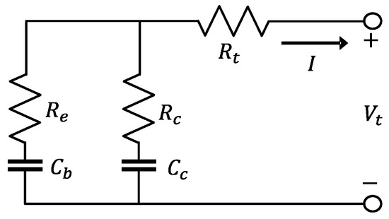
Figure 6.
RC battery model.
According to the ADVISOR documentation [32], the experiment data of the hybrid pulse power characterization (HPPC) test procedure [33] is used to identify the open circuit voltage and the model parameters of a single battery cell, which can be expressed as functions of the SOC. The parameters of a single battery cell for RC battery model as shown in Figure 7. The subscript denotes the cell. The parameters of the battery pack can then be obtained as follows:
where and are the number of cells in series and parallel, respectively. The SOC of the RC model can be obtained using the voltages of the two capacitors as shown below [34]:
where and .
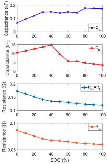
Figure 7.
Parameters of a single battery cell for RC battery model.
Because the RC battery model is a complicated model, which is used to simulate the actual battery dynamics, the internal resistance (Rint) battery model in Figure 8 is employed as the simple battery dynamics in the DP process.
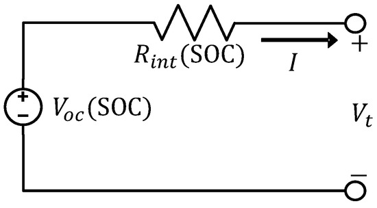
Figure 8.
Internal resistance battery model.
The electrical behavior of the internal resistance model can be described as:
where is the internal resistance; is the open circuit voltage. Both and are functions of the SOC. The parameters of a single battery cell for the Rint battery model identified using the HPPC are shown in Figure 9. Two lines are used to represent as functions of the SOC for battery charging and discharging, respectively. The parameters of the battery pack can then be obtained as follows:
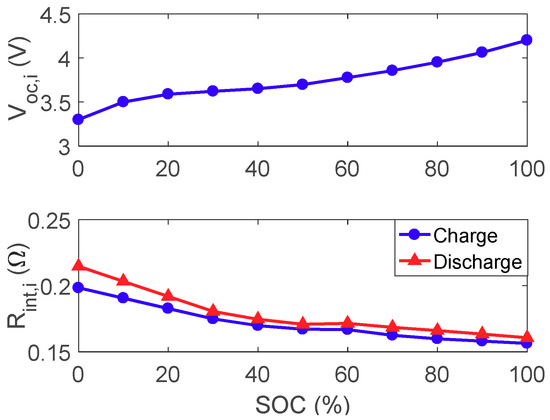
Figure 9.
Parameters of a single battery cell for Rint battery model.
From the definition, SOC of the Rint model can be expressed as:
where is the initial value of SOC; is the battery capacity. By differentiating the Equation (14), the differential equation can be obtained as follows:
The load current profile of 18 consecutive dynamic stress test (DST) [35] in Figure 10 is employed to evaluate the validity of using the Rint model to approximate the RC model.
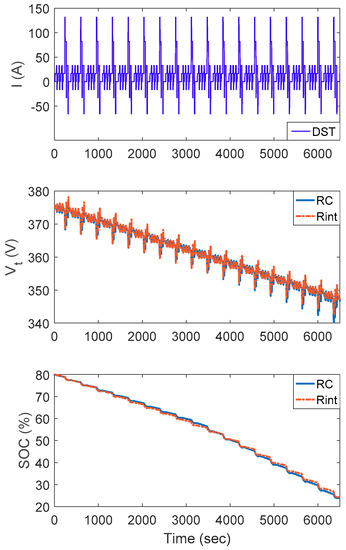
Figure 10.
SOC responses between RC and Rint models for 18 consecutive DST.
The load current is positive for discharging and negative for charging. Simulation results show that the terminal voltage and the SOC of the Rint model are close to those of the RC model. Hence, the Rint model can be utilized as the representative battery model for DP application.
3. Dynamic Programming
Dynamic programming is an effective tool to investigate the power management strategies of the REEV in this study. It can easily handle the constraints and obtain the optimum control policy for a given driving pattern by minimizing the fuel consumption. However, a simplified model is required to reduce the computation load of DP. The simplified model can be described as follows.
From the differential equation in Equation (15), the discrete approximation can be obtained as shown below:
where denotes the kth sample. Since the battery power is equal to the multiplication of the current and the terminal voltage , the current can be expressed as follows by substituting into Equation (12):
where the battery power can be expressed as:
where is electric power demand for the genset; is the electric power of the TM required to follow the driving pattern. The efficiency of the battery, , is a function of and SOC, and can be obtained by charging and discharging as shown below:
Therefore, the simplified model can be expressed as follows:
The simplified model of the target REEV can then be expressed in the discrete domain using the state-space representation as shown below:
where is the state variable which denotes the battery SOC; is the control input which denotes the electric power demand for the genset, .
The optimal fuel economy of PHEV can be achieved by maximizing the operation of the charge-depleting (CD) mode [19] such that the SOC drops to the minimum allowed value at the end of the driving cycle. To find the optimum control policy for the REEV to deplete the battery SOC at the end of a given driving pattern, a two-point boundary optimization problem with the initial SOC and the final SOC is formulated in this paper. The goal is to find the optimum control policy for minimizing the cost function as follows:
where is the duration of the driving cycle; is the instantaneous cost which is the fuel consumption of the genset as follows:
where is the fuel consumption rate of the mechanical power output of the genset . During the optimization, it is necessary to impose the following constraints to ensure safe operation of each component:
where the battery power is positive for discharging and negative for charging; and are the power limits for discharging and charging, respectively. The subscripts min and max denote the minimum and maximum allowed values, respectively. The optimal operating curve of the genset, which is obtained by combining the BSFC map of the engine and the efficiency map of the generator, is used for the DP analysis. The fuel consumption rate of the genset can then be modeled as a function of the genset power .
From the Bellman’s principle of optimality, it is known that whatever the initial state and initial decision are, the remaining decisions must constitute an optimum policy with regard to the state resulting from the first decision [36]. Therefore, the DP process is resolved backward from the final state to the initial state by separating it into a sequence of less complicated minimization problems as shown below:
At step:
At step, for :
where denotes the cost-to-go for each feasible state variable at each time step. The initial state and final state are the initial SOC and final SOC. A global optimum solution map is established backward in time by storing the optimum for each . From a specified initial state , the optimum control stored at can be used to find the next state by satisfying the battery dynamics in Equation (20). The optimum control stored at can then be used to find the next state . The optimum control policy can then be obtained forward-in-time by repeating the process until the final state is reached
4. Power Management Strategy
4.1. Operation Modes
According to the driver’s power request and the battery SOC, the operations of the target REEV can be divided into four modes, i.e., EV, genset, hybrid, and charging. If is less than and SOC is larger than , the REEV operates in the EV mode with the battery as the only power source. If is in the range between and , the REEV operates in the genset mode with the genset as the only power source. If is larger than and SOC is in the range between and , the REEV operates in the hybrid mode with both power sources. The genset outputs and the battery is used to supply the power gap of . If is less than and SOC is less than , the REEV operates in the charging mode with the genset as the only power source for providing electric power to the TM and charging the battery at the same time. Therefore, the power split ratio (PSR), which is defined as the ratio of the mechanical power output of the genset to the driver’s power request as shown in Equation (27), is employed to divide the operations of the REEV into four modes as shown in Table 2. If , the REEV is in the EV mode. If , the REEV is in the hybrid mode. If , the REEV is in the genset mode. If , the REEV is in the charging mode:
Table 2.
Operation modes of REEV.
4.2. Equivalent Fuel Consumption Minimization Strategy
An instantaneous cost function , that consists of the fuel consumption rate of the genset and the equivalent fuel consumption rate of the battery as shown below, is minimized to find the optimum PSR based on the equivalent fuel consumption minimization strategy (ECMS) concept:
where is the fuel consumption rate of the genset power ; is the equivalent fuel consumption rate of the battery power . can be obtained from the following equation:
where is the minimum BSFC of the engine; is used to indicate the battery power demand mode. is equal to 1 and 0 for discharging and charging, respectively. The equivalent factor is used to transform the electric power consumption into the equivalent fuel consumption rate. Since the minimization of is subject to the constraint of , a one-dimensional problem is formulated as follows:
According to the relationship between and in Figure 11, the PSRs are already defined for the EV and the genset modes. The golden section method [37], which is an optimization method to find the extremum of a function by successively narrowing down the range of values inside, is used to search the local optimum PSRs in the hybrid and the charging modes. The global optimum PSR can then be determined by comparing the costs of the local optimum PSRs at these four modes.
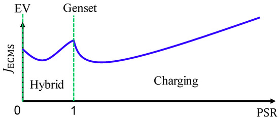
Figure 11.
The relationship between and at the four modes.
4.3. Adaptive Power Management Strategy
So as to develop the adaptive PMS suitable for different driving cycles, a charge-depleting problem based on the energy-to-distance ratio [38] is formulated in this paper. Since the optimal SOC-distance curve of DP looks like a line, the slope can be approximated by the energy-to-distance ratio, which is defined as the difference between the initial SOC and the minimum allowable SOC divided by the remaining travel distance. The desired trajectory of SOC for discharging the battery can then be obtained as shown in Figure 12.
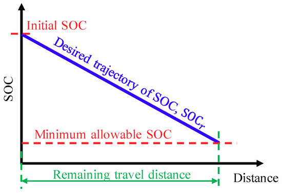
Figure 12.
The desired trajectory of SOC for discharging the battery.
The diagram of the proposed adaptive PMS is shown in Figure 13. If the SOC is less than the desired SOC, i.e., , S should be increased to reflect a more expensive cost of the electric power such that over discharging the battery can be prevented. If the SOC is larger than the desired SOC, S should be reduced to reflect a cheaper cost of the electric power such that discharging the battery is encouraged. The nominal equivalence factor Sn is obtained by minimizing the total fuel consumption for one NEDC driving cycle with the initial SOC equal to 80% and the energy-to-distance ratio equal to 0.549%. A self-organizing fuzzy controller (SOFC) [39] is utilized to modify the correction of Sn, i.e., ΔS, according to the SOC tracking error and the error change . The subscript k denotes the kth sample. The gains of the error and the error change, i.e., and , are obtained by minimizing the total fuel consumption. ΔS is obtained from the fuzzy inference decision and defuzzification operation. The overall equivalence factor S used for ECMS can then be obtained as:
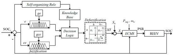
Figure 13.
Proposed adaptive power management strategy.
If S is large, the proposed adaptive PMS discourages the usage of electric power. If S is small, the proposed adaptive PMS encourages the usage of electrical power.
Membership functions and fuzzy rules can be designed to obtain a suitable performance for a given driving cycle. SOFC is utilized to modify these rules automatically for various driving cycles. The control correction of the ith fuzzy rule can be described as:
where is the correction rate. A large leads to large corrections of fuzzy rules which might cause oscillations of the system output. The control correction of each fuzzy rule is proportional to its excitation strength. is the performance weighting between and . The correction weightings and for the activated rules are obtained from the membership functions. The rule modification of the rule with the control correction can then be obtained as:
According to Equation (32), is zero only when or . When the absolute values of and are less than the threshold values which are set to be 0.00005 by trial and error, the rule is not updated for preventing unnecessary corrections around the zero point. The fuzzy control rules of the SOFC are shown in Table 3.
Table 3.
Fuzzy control rules.
5. Simulation and Experimental Results
A longitudinal vehicle model of the target REEV established in MATLAB/Simulink is used to evaluate the conventional TCS, the adaptive PMS and the DP. It is a forward-in-power model with a driver model to follow the driving cycle. A simplified backward-in-power vehicle model is established for DP to obtain the optimum control policy with respect to a given driving cycle. The conventional TCS operates the REEV in the EV mode when the SOC is larger than or equal to 20%. When the SOC is less than 20%, the genset is turned on and operated only at the most efficient working point to supply electric power until the SOC is more than or equal to 25%. The SOC is sustained in the low SOC range between 20% and 25% via the CS mode until the end of the driving event.
Figure 14 shows three different driving cycles: New European Driving Cycle (NEDC), Federal Test Procedure (FTP) and Urban Dynamometer Driving Schedule (UDDS). These driving cycles are repeated several times to obtain similar traveled distance to evaluate the performance of the conventional TCS, proposed adaptive PMS and DP. The traveled distances of 10 NEDC, 6 FTP and 9 UDDS cycles are 109.3, 106.6 and 107.9 km, respectively. For the desired SOC trajectory, the final SOC is set to be 20% which is the minimum allowable value to prevent the battery from over discharging. As for the initial SOC, it can be any value between 100%, i.e., fully charged, and 20%, i.e., fully discharged. The initial SOC is set to be 80% in this paper to match the condition of the target REEV. The energy-to-distance ratios of 10 NEDC, 6 FTP and 9 UDDS can then be obtained as 0.549%, 0.563% and 0.556%, respectively.
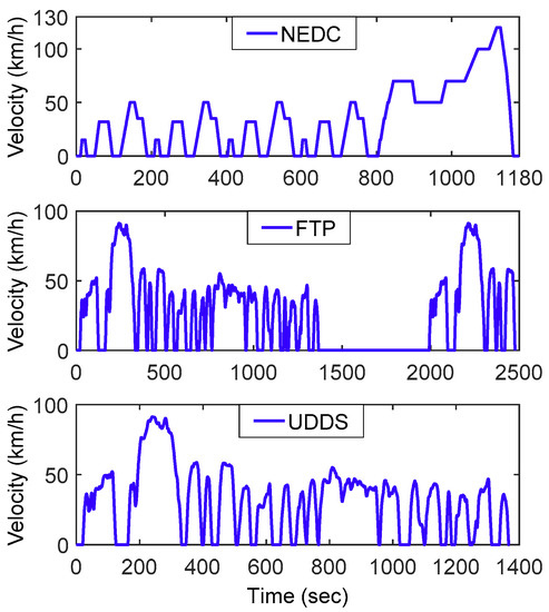
Figure 14.
Standard driving cycles.
Simulation results of the proposed adaptive PMS at the 1st of 10 NEDC cycles are shown in Figure 15. The nominal equivalence factor is 0.97. The equivalence factor is modified by the SOFC for tracking the desired . When the SOC response of the adaptive PMS is lower than the desired , is increased by the SOFC to indicate that discharging the battery results in a more expensive cost of the equivalent fuel consumption. The genset is turned on to generate electric power for the TM while charging the battery at the same time. When the SOC is greater or equal to , is reduced by the SOFC to indicate that discharging the battery results in a cheaper cost of the equivalent fuel consumption. The genset is turned off and the REEV is operated in the EV mode. The electric power demand of the TM obtained from the driver’s requested power is positive for accelerating and cruising. In the EV mode (PSR = 0), the battery provides electric power to the TM. In the hybrid mode (PSR 1), both the genset and the battery provide electric powers to the TM. In the genset mode (PSR = 1), only the genset provides electric power to the TM. In the charging mode (PSR > 1), the electric power provided by the genset is larger than the power required by the TM. The rest of the genset power is used to charge the battery.
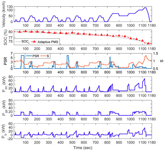
Figure 15.
Simulation results for the 1st NEDC.
The SOC responses of different control strategies for 10 NEDC, 6 FTP and 9 UDDS are shown in Figure 16, Figure 17 and Figure 18, respectively. The horizontal axis denotes the total traveled distance normalized by the traveled distance of one complete driving cycle. The proposed adaptive PMS can gradually discharge the battery by tracking the desired SOC such that the final SOC is approximately equal to 20%. The optimum control policies of the target REEV can be obtained using the DP for different driving cycles. Since the SOC response of the DP is very close to the desired , it supports the assumption of the desired and can be designed using the energy-to-distance ratio. In addition, the SOC response of the proposed adaptive PMS is close to the SOC response of the DP. Whether it is possible to approach the control performance of the DP using the proposed algorithm will be discussed via the following simulation and experiment studies.
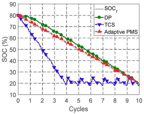
Figure 16.
SOC responses for 10 NEDC cycles.
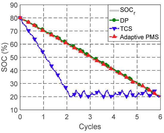
Figure 17.
SOC responses for six FTP cycles.
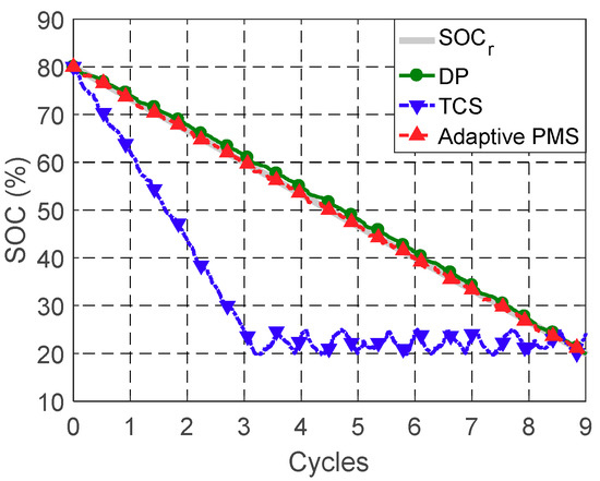
Figure 18.
SOC responses for nine UDDS cycles.
By using the fuel economy of TCS as the baseline, fuel economies and average battery charge/discharge powers of different control strategies for 10 NEDC, six FTP and nine UDDS are summarized in Table 4, Table 5 and Table 6, respectively. The associated fuel economies are corrected according to the SAE standard J1711 [40]. The TCS is easily implemented with the rule-based structure. However, it causes the lowest fuel economy, the highest average charge/discharge power and longest low SOC operation. When the TCS operates the REEV in the EV mode, only the battery provides electric power to the TM. Thus causes the largest average battery discharging power. In addition, the genset is only turned on in the low SOC range and operated at the most efficient working point to prevent over discharging the battery. This causes the largest average battery charging power and the longest low SOC operation. DP offers the best performance by improving the fuel economy of TCS by 24.3 to 28.1%. Meanwhile, DP can also reduce the average charging and discharging powers, and the time of low SOC operation of TCS by 48.1% to 50.4%, 31.4% to 34.9%, and 86.7% to 94.6%, respectively. However, it cannot be implemented in real-time due to the requirement of the future driving cycles and heavy computational loads. The proposed adaptive PMS, which does not require the information of future driving cycles and can be implemented in real-time, is capable of improving the fuel economy of TCS by 11.1% to 16%. Meanwhile, the proposed adaptive PMS can reduce the average charging and discharging powers, and the time at low SOC operation of TCS by 21.9% to 30.1%, 16.9% to 26.2%, and 85.7% to 90.9%, respectively. Since the battery capacity deteriorates with charging/discharging rates [41,42], the battery life is possible to be increased by reducing average charging/discharging powers. Meanwhile, the battery efficiencies can be increased by reducing the time of low SOC operation which leads to larger internal resistance as shown in Figure 9.
Table 4.
Comparison of TCS, adaptive PMS and DP for 10 NEDC.
Table 5.
Comparison of TCS, adaptive PMS and DP for 6 FTP.
Table 6.
Comparison of TCS, adaptive PMS and DP for 9 UDDS.
The energy flow diagram of the REEV is shown in Figure 19. The output energy of the genset is equal to the subtraction of the fuel usage loss, from the fuel energy, . can be divided into the 1st path with to drive the TM and the 2nd path with to charge the battery. The energy loss, , results from charging the battery with . The energy loss, , results from discharging the battery with the battery energy to drive the TM. The energy to drive TM, , is the summation of and .
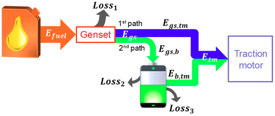
Figure 19.
Energy flow diagram of the REEV.
can be divided into and according to the ratio of to . and are the energy losses associated with the usages of and , respectively, as follows:
Due to different energy sources of , can be decomposed as follows:
where is the charging energy into the battery; is the initial electric energy in the battery which can be expressed as follows:
can be divided into and according to the ratio of to . and are the energy losses associated with the usages of and , respectively, as follows:
Thus can be divided into two parts as follows:
where is the output energy from the genset; is the output energy from the initial electric energy in the battery.
The energy usage and loss comparisons of TCS and adaptive PMS for 10 NEDC, 6 FTP and 9 UDDS are shown in Table 7, Table 8 and Table 9, respectively. “Overall” denotes the total value at the end of the driving cycle. “Low SOC” denotes the total value with the SOC between 20% and 25%. “Total loss” is the sum of , and . Table 10 shows the efficiencies and of the genset energy in the 1st path and 2nd path, respectively. These efficiencies are defined as follows:
Table 7.
Energy usage comparison of TCS and adaptive PMS for 10 NEDC.
Table 8.
Energy usage comparison of TCS and adaptive PMS for 6 FTP.
Table 9.
Energy usage comparison of TCS and adaptive PMS for 9 UDDS.
Table 10.
Energy usage efficiency of the genset in the 1st path and 2nd path.
As can be seen from Table 7, Table 8 and Table 9, the adaptive PMS allocates 63 to 67% of overall to , and the TCS allocates 36 to 38% of the overall to . Because the adaptive PMS operates the genset according to the PSR resulting from the closed-loop tracking control of SOC, the fuel energy, , through the 1st path is used more than the fuel energy, , through the 2nd path. As for the TCS, the genset is operated only in the low SOC. Therefore, the fuel energy, , through the 2nd path is used more than the fuel energy, , through the 1st path. As can be seen from Table 10, the energy usage efficiency of the genset in the 1st path is higher than that in the 2nd path. In the case of using the same and , the energy loss of the 1st path is just , but the energy loss of the 2nd path consists of (equal to ), and . Therefore, the usage of the 1st path can reduce the loss of energy conversion. These simulation results indicate that the proposed adaptive PMS can increase fuel economy by using the 1st path more to reduce the energy conversion losses, and possibly increase the battery life by reducing the time at low SOC operation.
The experiment setup for evaluating the proposed adaptive PMS is shown in Figure 20. The prototype REEV, which is an electric MPV with a genset mounted at the trunk space of the target vehicle, is used to evaluate the performance of the proposed adaptive PMS on a chassis dynamometer for 4 NEDC cycles. The experiment is paused for 20 min at the end of each cycle to calculate the fuel economy and calibrate the initial SOC using the open circuit voltage. The proposed adaptive PMS and the TCS are both implemented using the TeraSoft Micro-Box as a real-time controller. Basic vehicle parameters and efficiency maps are required to implement the proposed adaptive PMS. The Micro-Box communicates with the on-board hybrid control unit (HCU) of the prototype REEV via the controller area network (CAN bus) which is a robust vehicle bus standard for communication between microcontrollers and devices. The Micro-Box receives the accelerator pedal signal, SOC, wheel speed and genset speed from the HCU and sends the required engine torque and generator speed commands to the HCU. The required engine torque and generator speed commands are obtained by 1-D look-up tables of the desired genset power.
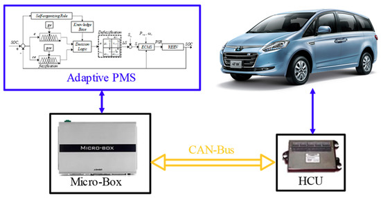
Figure 20.
Experiment setup of the prototype REEV.
The initial SOC is 50% at the beginning of the experiment. The SOC should be kept above 25% to prevent over discharging the battery. For the conventional TCS, the prototype REEV is operated at the EV mode for the first NEDC. The REEV is operated at the CS mode for the other NEDC cycles to maintain the SOC in the low SOC range between 25% and 30%. The proposed adaptive PMS tracks the desired SOC with an energy-to-distance ratio equal to 0.764% for the first three NDEC cycles and regulate the SOC around 25% for the last NEDC cycle.
The comparison of the TCS and the proposed adaptive PMS for the 4 NEDC experiment is shown in Table 11. The corrected fuel economies of the TCS and the proposed adaptive PMS are 24.4 km/L and 26.3 km/L, respectively. The proposed adaptive PMS can increase the fuel economy of TCS by 7.8%. In addition, the proposed adaptive PMS can reduce the average charge/discharge powers, and the time at low SOC operation of TCS by 7.9%, 11.7%, and 55.9%, respectively. Because the TCS uses the 2nd path more than the 1st path and has longer time at low SOC operation, it causes highest energy conversion losses, lowest fuel economy and highest average charge/discharge power. These experiment results indicate that the proposed adaptive PMS can increase fuel economy and possibly increase the battery life by reducing average charging/discharging powers and low SOC operations.
Table 11.
Comparison of TCS and adaptive PMS for the four NEDC experiments.
6. Conclusions
An adaptive power management strategy (PMS) design, based on the equivalent fuel consumption minimization strategy (ECMS) with the equivalent factor modified using a self-organizing fuzzy controller (SOFC) for a range extended electric vehicle (REEV), is described in this paper. The SOFC is used to adaptively modify the equivalence factor of the electric power consumption based on the SOC feedback for tracking the desired SOC, which is designed using the energy-to-distance ratio. An instantaneous cost function, that consists of the fuel consumption rate of the genset and the equivalent fuel consumption rate of the battery, is minimized using ECMS to find the optimum power distributions for the genset and the battery. Dynamic programming (DP) is employed to obtain the performance upper bound of the target REEV for a given driving cycle. Three driving cycles of 10 NEDC, six FTP and nine UDDS are used to evaluate the fuel economies and the average charging and discharging battery powers via simulation studies. By using the thermostat control strategy (TCS) and DP outcomes as the performance lower and upper bounds, respectively, simulation results show that the proposed algorithm is adaptive for different driving cycles and can increase the fuel economy of TCS by reducing the energy conversion losses. Meanwhile, the proposed algorithm is possible to extend the battery life by reducing the average charging and discharging powers, and increase the battery efficiencies by reducing the time of low SOC operation significantly. With the knowledge of technical parameters as shown in Section 2, the proposed algorithm can be implemented for similar powertrain configurations. Experiment results using a prototype REEV confirm that the proposed algorithm can achieve control performance similar to that of the simulation results.
Author Contributions
Conceptualization, B.-C.C. and J.-C.G.; methodology, B.-C.C. and J.-C.G.; software and hardware, J.-C.G.; validation, J.-C.G.; formal analysis, B.-C.C. and J.-C.G.; writing—original draft preparation, J.-C.G.; writing—review and editing, B.-C.C.; project administration, B.-C.C. and Y.-Y.W.
Funding
This research was funded by Ministry of Science and Technology (MOST, Taipei, Taiwan) and Hua-Chuang Automobile Information Technical Center (HAITEC, New Taipei, Taiwan), grant number MOST 106-3113-E-027-003-CC2.
Acknowledgments
The authors would like to thank the Ministry of Science and Technology (MOST, Taipei, Taiwan) and Hua-Chuang Automobile Information Technical Center (HAITEC) for supporting this research.
Conflicts of Interest
The authors declare no conflict of interest. The funding sponsors had no role in the design of the study; in the collection, analysis, or interpretation of data; in the writing of the manuscript, and in the decision to publish the results.
Nomenclature
| Abbreviations | |
| BSFC | brake specific fuel consumption |
| CAN | controller area network |
| CD | charge-depleting |
| CS | charge sustaining |
| DP | dynamic programming |
| ECMS | equivalent fuel consumption minimization strategy |
| EVs | electric vehicles |
| FTP | Federal Test Procedure |
| HEVs | hybrid electric vehicles |
| MPV | multi-purpose vehicle |
| NEDC | New European Driving Cycle |
| PFCS | power follower control strategy |
| PHEVs | plug-in hybrid electric vehicles |
| PMP | Pontryagin’s minimum principle |
| PMS | power management strategy |
| PSR | power split ratio |
| RC | resistance capacitance |
| REEV | range extended electric vehicle |
| SOC | state of charge |
| SOFC | self-organizing fuzzy controller |
| TCS | thermostat control strategy |
| TMs | traction motors |
| UDDS | Urban Dynamometer Driving Schedule |
| Symbols | |
| vehicle frontal area [m2] | |
| air drag coefficient | |
| bulk capacitor [F] | |
| surface capacitor [F] | |
| rotational inertia of the engine [kg-m2] | |
| rotational inertia of the generator [kg-m2] | |
| rotational inertia of the wheel [kg-m2] | |
| battery capacity [Ah] | |
| capacitor resistance [Ω] | |
| end resistance [Ω] | |
| terminal resistance [Ω] | |
| nominal equivalence factor | |
| braking torque [Nm] | |
| voltage across bulk capacitor [V] | |
| voltage across surface capacitor [V] | |
| open circuit voltage [V] | |
| terminal voltage [V] | |
| rotational damping coefficient | |
| rolling resistance coefficient | |
| gains of the error change | |
| gains of the error | |
| minimum BSFC of the engine [g/(kw-h)] | |
| fuel consumption rate [g/s] | |
| number of cells in parallel | |
| number of cells in series | |
| rolling radius of the wheel [m] | |
| correction weighting of the error change | |
| correction weighting of the error | |
| battery cell | |
| capacitor [F] | |
| energy [J] | |
| force [N] | |
| current [A] | |
| cost function | |
| instantaneous cost | |
| energy loss | |
| vehicle mass [kg] | |
| duration of the driving cycle | |
| power [kW] | |
| resistance [Ω] | |
| equivalent factor | |
| torque [Nm] | |
| voltage [V] | |
| error change | |
| error | |
| kth sample | |
| gear ratio | |
| control input | |
| vehicle speed [m/s] | |
| state variable | |
| correction rate | |
| battery power demand mode | |
| performance weighting | |
| efficiency [%] | |
| throttle angle [degree] | |
| tire slip ratio | |
| friction coefficient | |
| time constant | |
| rotational speed [rad/s] | |
| Subscripts | |
| battery | |
| engine | |
| electric | |
| final drive | |
| fuel | |
| genset | |
| internal | |
| maximum | |
| minimum | |
| open circuit | |
| requested | |
| reduction gear | |
| traction motor | |
| wheel | |
| longitudinal | |
| vertical | |
References
- U.S. Department of Energy. Hybrid and Plug-In Electric Vehicles. Available online: https://www.afdc.energy.gov/vehicles/electric.html (accessed on 28 October 2018).
- Tate, E.D.; Harpster, M.O.; Savagian, P.J. The electrification of the automobile: From conventional hybrid, to plug-in hybrids, to extended-range electric vehicles. SAE Int. J. Passeng. Cars Electron. Electr. Syst. 2009, 1, 156–166. [Google Scholar] [CrossRef]
- Yu, J.; Zhang, Y.; Liu, N.; Wang, B. Modeling and control strategy simulation of extended-range electric vehicle. In Proceedings of the International Conference on Transportation, Mechanical, and Electrical Engineering (TMEE), Changchun, China, 16–18 December 2011. [Google Scholar]
- Jalil, N.; Kheir, N.A.; Salman, M. Rule-based energy management strategy for a series hybrid vehicle. In Proceedings of the American Control Conference, Albuquerque, NM, USA, 6 June 1997; pp. 689–693. [Google Scholar]
- Sorrentino, M.; Rizzo, G.; Arsie, I. Analysis of a rule-based control strategy for on-board energy management of series hybrid vehicles. Control Eng. Pract. 2011, 19, 1433–1441. [Google Scholar] [CrossRef]
- Fajri, P.; Asaei, B. Plug-in hybrid conversion of a series hybrid electric vehicle and simulation comparison. In Proceedings of the 11th International Conference on Optimization of Electrical and Electronic Equipment, Brasov, Romania, 22–24 May 2008; pp. 287–292. [Google Scholar]
- Barsali, S.; Miulli, C.; Possenti, A. A control strategy to minimize fuel consumption of series hybrid electric vehicles. IEEE Trans. Energy Convers. 2004, 19, 187–195. [Google Scholar] [CrossRef]
- Konev, A.; Lezhnev, L.; Kolmanovsky, I. Control Strategy Optimization for a Series Hybrid Vehicle; SAE Technical Paper; SAE 2006 World Congress & Exhibition: Detroit, MI, USA, 2006. [Google Scholar]
- Wang, Z.; Li, W.; Xu, Y. A novel power control strategy of series hybrid electric vehicle. In Proceedings of the IEEE/RSJ International Conference on Intelligent Robots and Systems, San Diego, CA, USA, 29 October–2 November 2007; pp. 96–102. [Google Scholar]
- Pisu, P.; Rizzoni, G. A supervisory control strategy for series hybrid electric vehicles with two energy storage systems. In Proceedings of the IEEE Vehicle Power and Propulsion Conference, Chicago, IL, USA, 7 September 2005. [Google Scholar]
- Gao, J.P.; Zhu, G.M.G.; Strangas, E.G.; Sun, F.C. Equivalent fuel consumption optimal control of a series hybrid electric vehicle. Proc. Inst. Mech. Eng. Part D J. Autom. Eng. 2009, 223, 1003–1018. [Google Scholar] [CrossRef]
- Sezer, V.; Gokasan, M.; Bogosyan, S. A novel ECMS and combined cost map approach for high-efficiency series hybrid electric vehicles. IEEE Trans. Veh. Technol. 2011, 60, 3557–3570. [Google Scholar] [CrossRef]
- Sun, C.; Sun, F.; He, H. Investigating adaptive-ECMS with velocity forecast ability for hybrid electric vehicles. Appl. Energy 2017, 185, 1644–1653. [Google Scholar] [CrossRef]
- Geng, B.; Mills, J.K.; Dong, S. Energy management control of microturbine-powered plug-in hybrid electric vehicles using the telemetry equivalent consumption minimization strategy. IEEE Trans. Veh. Technol. 2011, 60, 4238–4248. [Google Scholar] [CrossRef]
- Serrao, L.; Onori, S.; Rizzoni, G. ECMS as a realization of Pontryagin’s minimum principle for HEV control. In Proceedings of the 2009 American Control Conference, St. Louis, MO, USA, 10–12 June 2009. [Google Scholar]
- Hou, C.; Ouyang, M.; Xu, L.; Wang, H. Approximate Pontryagin’s minimum principle applied to the energy management of plug-in hybrid electric vehicles. Appl. Energy 2014, 115, 174–189. [Google Scholar] [CrossRef]
- Musardo, C.; Rizzoni, G.; Guezennec, Y.; Staccia, B. A-ECMS: An adaptive algorithm for hybrid electric vehicle energy management. Eur. J. Control 2005, 11, 509–524. [Google Scholar] [CrossRef]
- Wang, R.; Lukic, S.M. Dynamic programming technique in hybrid electric vehicle optimization. In Proceedings of the IEEE International Electric Vehicle Conference, Greenville, SC, USA, 4–8 March 2012. [Google Scholar]
- Gong, Q.; Li, Y.; Peng, Z.R. Trip-based optimal power management of plug-in hybrid electric vehicles. IEEE Trans. Veh. Technol. 2008, 57, 3393–3401. [Google Scholar] [CrossRef]
- Yang, Y.; Hu, X.; Pei, H.; Peng, Z. Comparison of power-split and parallel hybrid powertrain architectures with a single electric machine: Dynamic programming approach. Appl. Energy 2016, 168, 683–690. [Google Scholar] [CrossRef]
- Chen, Z.; Liu, W.; Yang, Y.; Chen, W. Online energy management of plug-in hybrid electric vehicles for prolongation of all-electric range based on dynamic programming. Math. Probl. Eng. 2015. [Google Scholar] [CrossRef]
- Bianchi, D.; Rolando, L.; Serrao, L.; Onori, S.; Rizzoni, G.; Nazar, A.K.; Hsieh, T.M.; Kang, P. A rule-based strategy for a series/parallel hybrid electric vehicle: An approach based on dynamic programming. In Proceedings of the ASME 2010 Dynamic Systems and Control Conference, Cambridge, MA, USA, 12–15 September 2010. [Google Scholar]
- Larsson, V.; Johannesson, L.; Egardt, B. Analytic solutions to the dynamic programming subproblem in hybrid vehicle energy management. IEEE Trans. Veh. Technol. 2015, 64, 1458–1467. [Google Scholar] [CrossRef]
- Patil, R.M.; Filipi, Z.; Fathy, H.K. Comparison of supervisory control strategies for series plug-in hybrid electric vehicle powertrains through dynamic programming. IEEE Trans. Control Syst. Technol. 2014, 22, 502–509. [Google Scholar] [CrossRef]
- Peng, J.; He, H.; Xiong, R. Rule based energy management strategy for a series–parallel plug-in hybrid electric bus optimized by dynamic programming. Appl. Energy 2017, 185, 1633–1643. [Google Scholar] [CrossRef]
- Chen, B.C.; Wu, Y.Y.; Tsai, H.C. Design and analysis of power management strategy for range extended electric vehicle using dynamic programming. Appl. Energy 2014, 113, 1764–1774. [Google Scholar] [CrossRef]
- Zhang, S.; Xiong, R. Adaptive energy management of a plug-in hybrid electric vehicle based on driving pattern recognition and dynamic programming. Appl. Energy 2015, 155, 68–78. [Google Scholar] [CrossRef]
- Pei, D.; Leamy, J.M. Dynamic programming-informed equivalent cost minimization control strategies for hybrid-electric vehicles. J. Dyn. Syst. Meas. Control 2013, 135. [Google Scholar] [CrossRef]
- Chen, B.C.; Guan, J.C.; Li, J.H. Adaptive power management control of range extended electric vehicle. Energy Procedia 2014, 61, 67–70. [Google Scholar] [CrossRef][Green Version]
- Li, L.; Li, X.; Wang, X.; Liu, Y.; Song, J.; Ran, X. Transient switching control strategy from regenerative braking to anti-lock braking with a semi-brake-by-wire system. Veh. Syst. Dyn. 2016, 54, 27–283. [Google Scholar] [CrossRef]
- Chen, B.C.; Wu, Y.Y.; Wu, Y.L.; Lin, C.C. Adaptive power split control for a hybrid electric scooter. IEEE Trans. Veh. Technol. 2011, 60, 1430–1437. [Google Scholar] [CrossRef]
- Brooker, A.; Haraldsson, K.; Hendricks, T.; Johnson, V.; Kelly, K.; Kramer, B.; Markel, T.; O’Keefe, M.; Sprik, S.; Wipke, K.; et al. Advisor Documentation; National Renewable Energy Laboratory: Golden, CO, USA, 2003; Available online: http://adv-vehicle-sim.sourceforge.net/advisor_doc.html (accessed on 28 October 2018).
- Unkelhaeuser, T.; Smallwood, D. Freedom CAR Battery Test Manual for Power-Assist Hybrid Electric Vehicles; Department of Energy: Washington, DC, USA, 2003. [Google Scholar]
- Johnson, V.H. Battery performance models in ADVISOR. J. Power Sources 2002, 110, 321–329. [Google Scholar] [CrossRef]
- USCAR: The United States Council for Automotive Research. Manuals: Electric Vehicle Battery Test Procedures Manual. 1996. Available online: http://www.uscar.org/guest/publications (accessed on 28 October 2018).
- Bertsekas, D.P. Dynamic Programming and Optimal Control; Athena Scientific: Nashua, NH, USA, 1995. [Google Scholar]
- The Golden Section Search Method; University of Illinois at Chicago, Department of Mathematics, Statistics and Computer Science: Chicago, IL, USA, 2005.
- Kum, D.; Peng, H.; Bucknor, N.K. Optimal energy and catalyst temperature management of plug-in hybrid electric vehicles for minimum fuel consumption and tailpipe emissions. IEEE Trans. Control Syst. Technol. 2013, 21, 14–26. [Google Scholar] [CrossRef]
- Chen, B.C.; Chu, C.H.; Huang, S.J. Design of traction control system for electric scooter using self-organizing fuzzy control. Int. J. Veh. Des. 2013, 62, 87–100. [Google Scholar] [CrossRef]
- SAE International. Recommended Practice for Measuring the Exhaust Emissions and Fuel Economy of Hybrid-Electric Vehicles, Including Plug-in Hybrid Vehicles; SAE J1711: Detroit, MI, USA, 2010. [Google Scholar]
- Choi, S.S.; Lim, H.S. Factors that affect cycle-life and possible degradation mechanisms of a Li-ion cell based on LiCoO2. J. Power Sources 2002, 111, 130–136. [Google Scholar] [CrossRef]
- Wu, Y.; Keil, P.; Schuster, S.F.; Jossen, A. Impact of Temperature and Discharge Rate on the Aging of a LiCoO2/LiNi0.8Co0.15Al0.05O2 Lithium-Ion Pouch Cell. J. Electrochem. Soc. 2017, 164, 1438–1445. [Google Scholar] [CrossRef]
© 2019 by the authors. Licensee MDPI, Basel, Switzerland. This article is an open access article distributed under the terms and conditions of the Creative Commons Attribution (CC BY) license (http://creativecommons.org/licenses/by/4.0/).