Abstract
In this study, the influences of the flow cut and axial lift of the impeller on the aerodynamic performance of a transonic centrifugal compressor were analyzed. The flow cut is a method to reduce the flow rate by decreasing the impeller passage height. The axial lift is a method of increasing the impeller passage height in the axial direction, which increases the impeller exit width (B2) and increases the total pressure. A NASA CC3 transonic centrifugal compressor with a backswept angle was used as a base compressor. After applying the flow cut, the total pressure at the target flow rate was lower than the total pressure at the design point due to the increase in the relative velocity at the impeller exit. After applying the axial lift, the total pressure at the design flow rate was increased, which was caused by the reduction in the relative velocity as the passage area at the impeller exit was increased. By applying the flow cut and axial lift methods, it was shown that the variation in relative velocity at the impeller exit has a significant effect on the variation in total pressure. In addition, it was found that the relative velocity at the impeller exit of the target flow rate is maintained similar to the base impeller when the flow cut and the axial lift are combined. Therefore, by combining the flow cut and the axial lift, three transonic centrifugal impellers with flow fractions of 0.7, 0.8, and 0.9 compared to the design flow rate were newly designed.
1. Introduction
Centrifugal compressors are used in various fields such as power generation, chemistry, and environmental plants, and therefore compressors with varying performance (pressure and flow rate) are required [1,2]. Designing the compressors required for each field requires the efforts and time of engineers [3,4,5] and significant investments by compressor manufacturers [6,7]. Therefore, it is desirable to design a new compressor by modifying the impeller for a compressor that has already been designed and proven in performance. It is also necessary to design compressors as a group within a specific flow range by combining impeller modification methods.
There are two advantages to designing the impeller as a group within a certain range. The first is that compressors with the performance required for each field be manufactured quickly and at a low cost, and the design success rate can be increased. This is because only the impeller is modified in the design of compressors with different performances, so the casings, shafts, and bearings of proven compressors can be used. Second, all compressors can be operated stably in the operating range with a sufficient surge margin because the impeller modification method can shift the performance curve to match the operating range of the compressors required for each field.
The most popular impeller modification methods are the flow cut and axial trim methods [8,9]. The flow cut method reduces the flow rate by decreasing the impeller passage height. When this method is applied, the performance curve is shifted in the direction of decreasing flow rate. The axial trim method decreases the impeller passage height in the axial direction, which decreases impeller exit width (B2) and the total pressure. This method is generally used to reduce the total pressure in impellers with a backswept angle. In addition, the flow lift and axial lift methods increase the impeller passage height, unlike the flow cut and axial trim methods. When the flow lift method is applied, the flow rate is increased because the impeller passage height is increased, and when the axial lift is applied, the total pressure is increased because B2 is increased. However, when the flow lift and axial lift methods are applied to the impeller, the size and weight of the aerodynamic components of the compressor are increased, and more power is required. Therefore, these methods are not generally applicable because it is necessary to redesign the casings, shafts, and bearings and reselect the motor.
The impeller modification methods such as the flow cut and axial trim methods have long been used by most centrifugal compressor manufacturers to design new compressors, and in 2001, Rogers first introduced the flow cut method in the paper [10]. Rogers recommended that the flow cut method should be applied only at a nondimensional specific speed (Ns) between 0.5 and 1.2. Tim David (2006) and Donghui Zhang (2010) applied the flow cut method by up to 75% (a flow fraction of 0.25 compared to the design flow rate of the base compressor) to the impeller of an industrial compressor with a nondimensional specific speed (Ns) of 0.06. However, Tim David and Donghui Zhang recommended applying only 50% of the flow cut to the impeller [11,12]. Daniel Swain (2014) applied the flow cut and axial trim methods to different types of impellers such as a transonic impeller with a relative Mach number between 0.8 and 1.2 at the impeller inlet tip, a closed impeller without tip clearance, and an impeller without a splitter [13]. For most impellers, the ratio of the reduced flow rate and the reduced passage area was not 1:1 after applying the flow cut method. Daniel Swain also noted that applying the axial trim method increases the relative velocity at the impeller exit and reduces the total pressure. Shin et al. (2015, 2017) designed various industrial compressors using the flow cut and scaling methods. Shin et al. noted that the pressure at the target flow rate was different from the pressure at the design flow rate after applying the flow cut method because the work coefficient changed [14,15].
In previous studies, after applying the flow cut method to the impellers, the ratio of the passage area reduction and the flow rate reduction was not 1:1. In most impellers, the performance curve was shifted more to the left, which means that the target flow rate is shifted to near the choke and the relative velocity is increased at the impeller exit of the target flow rate. In the centrifugal impeller with a backswept angle, an increased relative velocity at the impeller exit causes a reduction of the total pressure [16,17]. The reason for this reduction is that the increased relative velocity reduces the angle of the absolute velocity (Meridional angle convention). This reduction means that the tangential velocity is reduced and the work coefficient is reduced, which results in a reduction in the total pressure [18,19]. Therefore, the relative velocity at the impeller exit must be maintained at the level of the impeller of the base compressor to design an impeller for which the total pressure at the target flow rate is similar to the total pressure at the design flow rate.
Designing an impeller for which the total pressure at the target flow rate is similar to the total pressure at the design flow rate is not easy using the impeller modification method with only a flow cut applied. The reason is that it is very difficult to establish a 1:1 match between the reduced passage area and the reduced flow rate. However, if the axial lift method is used in combination with the flow cut method, this problem can be solved because after the flow cut is applied, the reduced total pressure at the target flow rate can be increased to a total pressure that is similar to the design flow rate by applying the axial lift method.
The main objectives in this study are to analyze the influences of the flow cut and axial lift of the impeller on the aerodynamic performance of a transonic centrifugal compressor and to design transonic impellers by combining these methods. A NASA CC3 transonic centrifugal impeller with a backswept angle of −50° (Meridional angle convention) is selected to carry out this study, as shown in Figure 1a. The flow cut, axial lift, and combined flow cut and axial lift methods are applied to the impeller, as shown in Figure 1b–d. Three-dimensional, compressible, steady Navier–Stokes equations were solved to investigate the aerodynamic performance of each impeller.
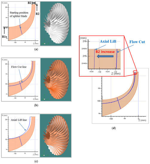
Figure 1.
A base impeller and three impeller modification methods. (a) Base impeller; (b) flow cut; (c) axial lift; (d) combination of flow cut and axial lift method.
2. Numerical Method
2.1. Compressor Model
To carry out this study, the NASA CC3 transonic centrifugal compressor developed by NASA Glenn Research Center was used as a base compressor [20]. This compressor consists of an inlet, an impeller, and a vaneless diffuser. The impeller of the base compressor has a backswept angle of −50° degrees (Meridional angle convention). The total-to-total pressure ratio was approximately 4.17 at the design mass flow rate (4.54 kg/s), and the relative Mach number was approximately 0.85 at the impeller inlet tip of the design point. The impeller consists of 15 main blades and 15 splitter blades. Details about the impeller radius, rotational speed, and non-dimensional specific speed (Ns) are shown in Table 1. The AxCent aerodynamic design software developed by Concepts NREC was used in the study. The 3D shape of the impeller shown in Figure 2 was made by using this software. The inlet was made of a bell-mouth type, and the vaneless diffuser was made sufficiently longer than the data measuring position (R3 = 255 mm) on the impeller exit.

Table 1.
The specifications of the NASA CC3 compressor with a vaneless diffuser.
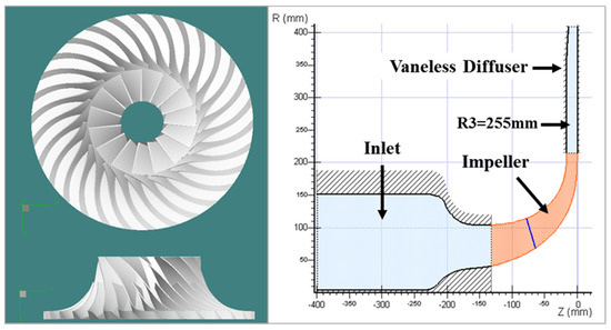
Figure 2.
The modeling of the NASA CC3 centrifugal compressor using the AxCent design software.
2.2. Computational Grid and Validation
The computational domain was selected as a single passage, as shown in Figure 3. The multi-block hexahedral structured grid was used to carry out CFD simulation, and the ANSYS Turbo Grid (19.3, ANSYS, Canonsburg, PA, USA) was used to generate the mesh, as shown in Figure 3a. The number of grid points for the streamwise, spanwise, and pitchwise directions were 249, 47, and 28, respectively. Thirty grid points were used in the tip clearance to preserve the tip leakage flow accurately. Twenty-one O-grid points were used around the main blade and splitter blade surfaces. To use the SST turbulence model, Y+ was set to almost 2 or less, as shown in Figure 3b [21]. Because the pitch ratio between the rotating and stationary frames was 1, the frozen rotor interface was used. The inlet boundary conditions are the total pressure and the total temperature. The outlet boundary conditions are the mass flow rate and the average static pressure, as shown in Figure 3c. First, the performance curves were obtained by applying the exit average static pressure conditions, and finally, the performance curves were obtained by applying the exit mass flow rate condition at the design point and near the surge. When the exit mass flow rate was applied at the design point and near the surge, the initial value was used as the result closest to the target point among the results calculated by the exit average pressure conditions. The reason is that the calculation using the mass flow condition takes a long time to converge. Turbulence intensity was set to 5% at the inlet and the length of the inlet domain was extended long enough to reduce the effects of boundary condition on the flow field. In addition, the tip clearance of the impeller was set to 0.2 mm. In relation to the impellers designed using flow cut and axial lift, the grid and boundary condition were set in the same method as the base impeller.
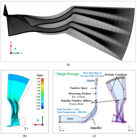
Figure 3.
Grid generation and computational domain of the base compressor. (a) Grid generation; (b) Y plus; (c) computational domain.
The grid independence study is shown in Figure 4a,b, and the total-to-total pressure ratio and the total-to-total isentropic efficiency are compared. As a result, the relative error decreased from more than 2.4 million grids to less than 0.1%. Thus, approximately 2.8 million grids were selected for this study, taking into account some margin. To predict the performance of the impeller, the 3D Steady Reynolds-Averaged Navier–Stokes equations were solved using ANSYS CFX software (19.3, ANSYS, Canonsburg, PA, USA). The SST turbulence model was used as the turbulence model, and the CFD results of the impeller of the base compressor were compared with the experimental data to validate the analytical method of this study [22]. The performance curves are shown in Figure 5a,b. The total-to-total pressure ratio is in good agreement with the experimental results. For the total-to-total efficiency, the CFD results were predicted to be approximately 1.5%–2% higher than the experimental results. Because the CFD was calculated for adiabatic conditions, the CFD efficiency value was slightly higher than the experimental value.
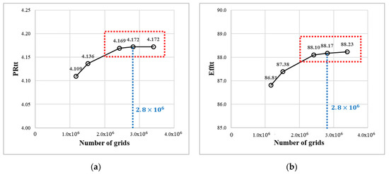
Figure 4.
Grid independency test of the base compressor. (a) Total-to-total pressure ratio; (b) total-to-total efficiency.
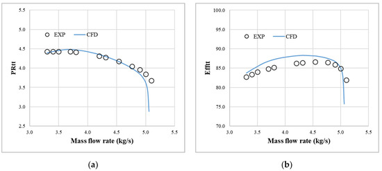
Figure 5.
Comparison of the predicted results and the experimental data for validation. (a) Total-to-total pressure ratio; (b) total-to-total efficiency.
3. Numerical Results
3.1. Flow Cut
The flow cut method reduces the flow rate by decreasing the impeller passage height, as shown in Figure 1b. When this method is applied, the performance curve is shifted to the left (in the direction of decreasing flow rate) because the passage area is reduced. Thus, this method is used to design compressors with different performances by reducing the flow rate. In this study, the passage area inside the impeller was calculated using the annulus area. The annulus area is calculated using the quasi-orthogonal (QO) lines, as shown in Figure 6. The following Equations (1)–(2) are used to calculate the annulus area.
where, and, are the angles at which the QO line meets the hub and shroud lines, respectively, and are used to calculate the effective angles (). The effective angle, which is calculated using Equation (1), is the angle of the root mean square (RMS) located between the hub and shroud lines. Finally, the annulus area is calculated by substituting the effective angles, the radius of the hub (), the radius of the shroud (), and the QO line () into Equation (2).
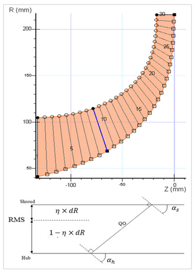
Figure 6.
Q.O. (Quasi-orthogonal) lines in the impeller.
To continuously design impellers with different performances by reducing the flow rate, three impellers (FC10, FC20, FC30) corresponding to flow fractions of 0.9, 0.8, and 0.7 compared to the design flow rate were designed, as shown in Figure 7a. Table 2 shows the impeller inlet shroud radius (R1s), the impeller exit width (B2), and the annulus area at the impeller inlet and exit. In addition, the annulus area inside the impeller is shown as Meridional (%), as shown in Figure 7b, and the annulus area is decreased in proportion to the flow cut percentage.
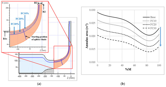
Figure 7.
Aerodynamic design of FC10, 20, and 30 models corresponding to fractions of 0.9, 0.8, and 0.7 of the annulus area of the base compressor using the flow cut method. (a) Meridional view; (b) decreased annulus area with respect to the flow cut method.
Table 2.
The blade height and annulus area at the impeller inlet and exit (flow cut).
The performance curves of the FC 10, 20, and 30 are predicted, as shown in Figure 8. The flow rate equal to the total pressure of the design flow rate was smaller than the target flow rate, and the total pressure at the target flow rate was less than the total pressure at the design flow rate. This result shows that the decrease in the flow rate was more than the decrease in the passage area.
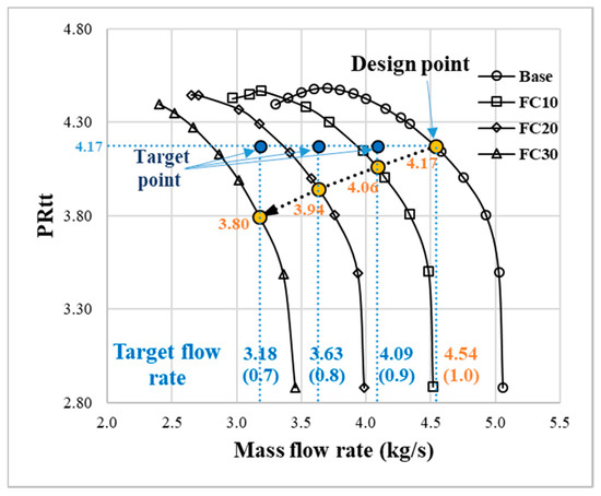
Figure 8.
Reduced total pressure at the target flow rate after applying the flow cut method.
3.2. Axial Lift
The axial lift method increases the impeller passage height in the axial direction, as shown in Figure 1c, which increases B2 and the total pressure. When B2 is increased, the passage area at the impeller exit increases, and the relative velocity () decreases. Because the blade speed at the impeller exit () is constant, tangential velocity () increases. As a result, the work coefficient is increased and the total pressure is increased.
To analyze the influence of the axial lift, B2 was set to 18 mm (AL-1) and 19 mm (AL-2) and increased by 1 mm and 2 mm from the base impeller, as shown in Figure 9a. Table 3 shows the impeller inlet shroud radius (R1s), the impeller exit width (B2), and the annulus area at the impeller inlet and exit. In addition, the annulus area inside the impeller is shown in Meridional (%), which can be seen to increase proportionally with respect to the axial lift, as shown in Figure 9b.
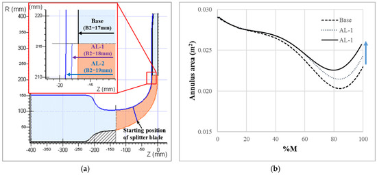
Figure 9.
Aerodynamic design of AL-1 and AL-2 with the B2 value increased by 1 mm and 2 mm over the B2 value of the base impeller using the axial lift method. (a) Meridional view; (b) increased annulus area with respect to the axial lift method.
Table 3.
The blade height and annulus area at the impeller inlet and exit (axial lift).
The performance curves of AL-1 and AL-2 are predicted, as shown in Figure 10. After the axial lift was applied, there was no significant change in the choking flow rate because there is no change in the passage area at the impeller inlet. However, the total-to-total pressure ratio increased at all flow rates except the choking flow rate. At the design flow rate, the total-to-total pressure ratio increased by approximately 3% as B2 increased by 1 mm.
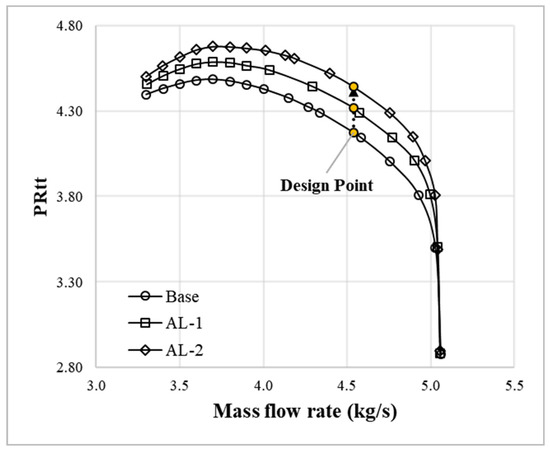
Figure 10.
Increased total pressure at the target flow rate after applying the axial lift method.
3.3. Combination of Flow Cut and Axial Lift
The combined flow cut and axial lift method, which uses the flow cut and axial lift methods together, is proposed in this study to increase the reduced total pressure to the design flow rate after the flow cut is applied, as shown in Figure 1d. In particular, this method can be used for centrifugal impellers with a backswept angle such as the base impeller of this study. If only the axial lift method is applied to the centrifugal compressor, components such as the shafts, gears, and bearings of the base compressor may not be used due to the increase in the weight of the aerodynamic parts. However, if the axial lift method is applied after applying the flow cut method, as shown in Figure 1d, the components of the base compressor can be used because the weight of the aerodynamic parts is not increased compared with the weight of the base compressor.
When the axial lift method is applied after applying the flow cut method, B2 was increased, as shown in Table 4. This reduces the relative velocity at the impeller exit and increases the total pressure. The impellers for which a combination of the flow cut and axial lift methods were used are represented in the order of 1, 2, and 3. The B2 values of FC 10, 20, and 30 were 15.3 mm, 13.6 mm, and 11.9 mm, respectively. When applying the combined flow cut and axial lift method, the B2 value was increased by approximately 2%, as shown in Table 4. After applying the combined flow cut and axial lift method, the modified annulus area inside the impeller is shown in Figure 11.
Table 4.
The variation of B2 with respect to the combined flow cut and axial lift method.
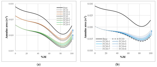
Figure 11.
Increased annulus area in the impeller by using the combined flow cut and axial lift method. (a) Base, FC 10, and FC 20; (b) base and FC 30.
Figure 12 shows the CFD results at the target flow rate after applying the combined flow cut and axial lift method. The total-to-total pressure ratio was constantly increased by increasing B2, as shown in Figure 12b, and the impellers with a total-to-total pressure ratio that was approximately the same as that of the base impeller were FC10-2, FC20-5, and FC30-8. Figure 13 shows the performance curves of FC10-2, FC20-5, and FC30-8 using the combined flow cut and axial lift method. The total-to-total pressure ratio at the target flow rate is almost the same as the total-to-total pressure ratio at the design point of the base impeller.
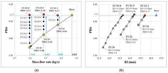
Figure 12.
Increased total-to-total pressure at the target flow rate with respect to the combined flow cut and axial lift method. (a) Total-to-total pressure ratio versus mass flow rate (kg/s); (b) total-to-total pressure ratio versus B2.
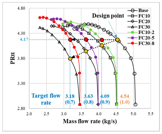
Figure 13.
Comparison of performance curves of the flow cut method only and the combined flow cut and axial lift method.
4. Discussion
4.1. Characteristic of Base Impeller
Figure 14 shows the flow fields at five operating points in the performance curve: Near choke, between near choke and design point, design point, between design point and near surge, and near surge. Figure 14a shows the relative Mach number at the 50% blade-to-blade position. The relative Mach number of the impeller inlet tip is approximately 0.8 to 0.85 at the design point and approximately 1.1 to 1.2 near the choke, which means that the base impeller shows the general characteristics of a transonic compressor with a relative Mach number between 0.8 and 1.2 at the impeller inlet tip. In addition, Figure 14b shows the flow fields at 80% span from point 1 to point 5, and it can be seen that the total-to-total pressure ratio decreases sharply when the shock wave occurs between point 1 and point 2. At point 5, a flow blockage occurred on the suction surface of the main blade and on the pressure surface of the splitter blade, and as a result, the total pressure decreases from point 4 to point 5. In this impeller, shock waves are generated only near the choke, not between the design point and near the surge. Therefore, the transonic centrifugal compressor used in this study is a compressor that is very useful for industrial applications if it can be controlled properly within this operating range so that shock waves are not generated.
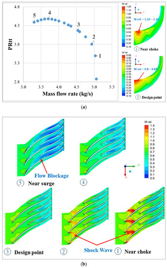
Figure 14.
Flow fields in the base impeller. (a) Contour of relative Mach number (Mrel) on meridional view; (b) contour of relative Mach number (Mrel) at 80% span.
4.2. Correlation of Velocity and Total Pressure at Impeller Exit
To analyze the correlation between the velocity and the total pressure at the impeller exit, relative velocity, tangential velocity (), meridional velocity (), and total pressure were analyzed.
4.2.1. Relative Velocity
Figure 15 shows the variation of relative velocity at the impeller exit with respect to the flow cut. After the flow cut was applied, the relative velocity at the impeller exit was increased; as the flow cut percentage increased, the relative velocity increased even more.
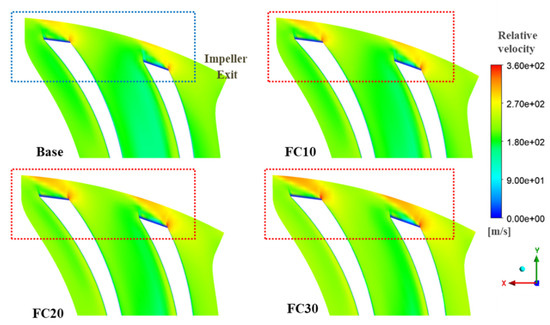
Figure 15.
Increased relative velocity after applying flow cut at impeller exit (at Mid-span).
In the centrifugal impeller with a backswept angle, increasing the relative velocity at the impeller exit causes a problem. Because the increased relative velocity reduces the angle of the velocity (Meridional angle convention), as shown in Figure 16a, the tangential velocity is reduced, as shown in Figure 16b. Eventually, the work coefficient is reduced based on Equation (3).
where and are the tangential velocity and the blade speed at the impeller exit, respectively. The head decreases when the work coefficient is reduced, and the total pressure is reduced.
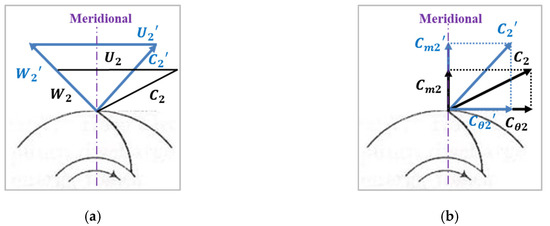
Figure 16.
Velocity triangle change of the centrifugal impeller with a backswept angle at the impeller exit. (a) Correlation between the increased relative velocity and the changed absolute velocity angle; (b) correlation between the changed absolute velocity angle and the decreased magnitude of the tangential velocity.
In Figure 17, as axial lift was applied, B2 was increased and relative velocity was decreased. In Figure 18, the relative velocity of FC10, FC20, and FC30 were higher than that of base impeller at the impeller exit, while the relative velocity of FC10-2, FC20-5, and FC30-8 were similar to that of base impeller.
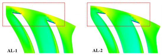
Figure 17.
Decreased relative velocity after applying axial lift at impeller exit (at Mid-span).
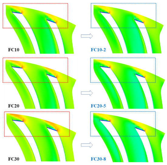
Figure 18.
The same relative velocity of the target flow rate and design flow rate of base impeller after applying the combination of flow cut and axial lift at impeller exit (at Mid-span).
4.2.2. Tangential/meridional Velocities at the Impeller Exit
Figure 19a shows the tangential velocity () at the trailing edge of the impeller. When the flow cut was applied, the tangential velocity was reduced due to the higher relative velocity at the impeller exit. However, by applying the axial lift after the flow cut, the tangential velocity was increased to the similar level as the base.
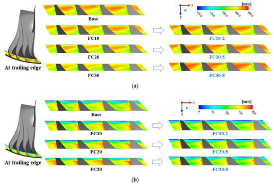
Figure 19.
Tangential/meridional velocities at impeller exit. (a) Tangential velocity (); (b) Meridional velocity ( ).
Figure 19b shows the meridional velocity () at the trailing edge of the impeller. The meridional velocity was increased after applying the flow cut because the relative velocity was also increased at the impeller exit. However, when axial lift was used after the flow cut, the meridional velocity was decreased. Therefore, it is confirmed that the flow phenomenon at the impeller exit could be maintained similar to that of the base impeller, when the flow cut and axial lift are applied together.
4.2.3. Total Pressure at Impeller Exit
Figure 20 shows the total pressure at the trailing edge of the impeller. Applying the flow cut showed that the total pressure is decreased at the impeller exit. However, when axial lift was combined with the flow cut, the total pressure was increased to the similar value as that of the base.
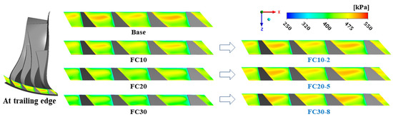
Figure 20.
Total pressure at impeller exit.
Increasing the relative velocity after applying the flow cut reduced the tangential velocity, which results in total pressure reduction. However, as the axial lift was applied after the flow cut, the tangential velocity and total pressure were increased to those of the base level. Therefore, it was proved that the relative velocity at the impeller exit should be kept almost constant compared to reference impeller for designing a new impeller by the impeller modification methods.
5. Conclusions
In this study, the influences of the flow cut and axial lift of the impeller on the aerodynamic performance of a transonic centrifugal compressor were analyzed, and three transonic centrifugal impellers with flow fractions of 0.7, 0.8, and 0.9 compared to the design flow rate were newly designed by applying the combined flow cut and axial lift methods.
- The NASA CC3 transonic centrifugal compressor with a backswept angle of −50° was used as the base compressor to carry out the study. The aerodynamic performance of the impeller of the base compressor was analyzed. There was a strong shock wave at the impeller inlet tip near the choke; however, in the range of the design point to the surge, no shock wave was observed. Therefore, the high-pressure transonic centrifugal impeller used in this study will be useful for industrial applications when they operate properly within the operating range without shock waves.
- To analyze the influence of the flow cut method, the target flow rate of the flow cut was set at flow fractions of 0.7, 0.8, and 0.9 compared to the design flow rate. After applying the flow cut, the total pressure at the target flow rate was lower than the total pressure at the design point due to the increase in the relative velocity at the impeller exit. In the centrifugal impeller with a backswept angle, the increased relative velocity reduces the angle of the absolute velocity (Meridional angle convention), which results in a reduction of the tangential velocity and the work coefficient.
- To analyze the influence of the axial lift, the B2 value was increased by 1 mm and 2 mm compared to the value of the base impeller. After applying the axial lift method, the total pressure at the design flow rate was increased due to the decrease in the relative velocity caused by increasing the passage area at the impeller exit.
- Applying the flow cut and axial lift methods showed that the variation in the relative velocity at the impeller exit has a significant effect on the variation of the total pressure. In addition, it was found that the relative velocity at the impeller exit of the target flow rate is similar to that of the base impeller when the flow cut and axial lift methods are applied together. Therefore, by combining these methods, three transonic centrifugal impellers with flow fractions of 0.7, 0.8, and 0.9 compared to the design flow rate were newly designed. These conclusions are expected to be guidelines to design impellers within a specific flow range by applying impeller modification methods to transonic centrifugal impellers with a backswept angle.
Author Contributions
All authors contributed to this work by collaboration. K.S.P. is the main author of this manuscript. I.H.J., S.J.Y., S.Y.L., A.Z., and J.T.C. assisted and provided useful suggestions in the contents of research. All authors approved the publication.
Funding
This research received no external funding.
Conflicts of Interest
The authors declare no conflict of interest.
Nomenclature
| AL | Axial lift |
| B | Blade height |
| C | Absolute velocity |
| CFD | Computational fluid dynamics |
| Efftt | Total-to-total efficiency |
| FC | Flow cut |
| M | Mach number |
| Ns | Nondimensional specific speed |
| PR | Pressure ratio |
| PRtt | Total-to-total pressure ratio |
| R | Blade radius |
| RMS | Root mean square |
| QO | Quasi-orthogonal |
| U | Blade speed |
| W | Relative velocity |
Mathematical Symbols
| Angle between QO lines and RMS contour | |
| Angle between QO lines and hub contour | |
| Angle between QO lines and shroud contour | |
| Backswept angle | |
| Fraction between the shroud and RMS contour |
Subscripts
| 1 | Impeller inlet |
| 2 | Impeller exit |
| 3 | Measuring position |
| b | Blade |
| h | Hub |
| s | Shroud |
| t | Tip |
| Meridional direction | |
| Tangential direction |
References
- Harvey, S.; Eng, P. Centrifugal Compressors in Ethylene Plants. Chem. Eng. Prog. 2017, 113, 28–32. [Google Scholar]
- Malik, A.; Zheng, Q.; Qureshi, S.R.; Zaidi, A.A.; Ahmad, S.A. Design and aerodynamic analysis of 50 kw combine cooling, heating and power (cchp) micro-gas turbine plant and its vaneless centrifugal compressor. In Proceedings of the 2018 IEEE 5th International Conference on Engineering Technologies and Applied Sciences (ICETAS), Krung, Thailand, 22–23 November 2018; pp. 1–6. [Google Scholar]
- Came, P. The development, application and experimental evaluation of a design procedure for centrifugal compressors. Proc. Inst. Mech. Eng. 1978, 192, 49–67. [Google Scholar] [CrossRef]
- Came, P.; Robinson, C. Centrifugal compressor design. Proc. Inst. Mech. Eng. Part C J. Mech. Eng. Sci. 1998, 213, 139–155. [Google Scholar] [CrossRef]
- Lüdtke, K.H. Process Centrifugal Compressors: Basics, Function, Operation, Design; Application; Springer Science & Business Media: Berlin/Heidelberg, Germany, 2004. [Google Scholar]
- Xu, C. Design experience and considerations for centrifugal compressor development. Proc. Inst. Mech. Eng. Part G J. Aerosp. Eng. 2007, 221, 273–287. [Google Scholar] [CrossRef]
- Xu, C.; Amano, R.S. Empirical design considerations for industrial centrifugal compressors. Int. J. Rotat. Mach. 2012, 2012, 184061. [Google Scholar] [CrossRef]
- Engeda, A. Effect of Impeller Exit Width Trimming on Compressor Performance. In Proceedings of the 8th International Symposium on Experimental and Computational Aerothermodynamics of Internal Flows, Lyon, France, 2–5 July 2007. [Google Scholar]
- Swain, D.; Engeda, A. Performance impact of impeller blade trimming on centrifugal compressors. Proc. Inst. Mech. Eng. Part A J. Power Energy 2014, 228, 878–888. [Google Scholar] [CrossRef]
- Rodgers, C. ASME Turbo Expo 2001: Centrifugal Compressor Blade Trimming for a Range of Flows. In Proceedings of the Power for Land, Sea, and Air, New Orleans, LA, USA, 4–7 June 2001; p. V001T03A020. [Google Scholar]
- David, T.; Zhang, D.; Cave, M. Frictional effects on a base and a flow-trimmed impeller of a low specific speed industrial compressor. In Proceedings of the ASME Turbo Expo 2006: Power for Land, Sea, and Air, Barcelona, Spain, 8–11 May 2006; pp. 1121–1130. [Google Scholar]
- Zhang, D.; Di Liberti, J.-L.; Cave, M. A CFD Study on a Base and a Flow-Trimmed Low Specific Speed Centrifugal Compressor. In Proceedings of the ASME 2010 International Mechanical Engineering Congress and Exposition, Vancouver, BC, Canada, 12–18 November 2010; pp. 89–94. [Google Scholar]
- Swain, D.; Engeda, A. Effect of impeller blade trimming on the performance of a 5.5: 1 pressure ratio centrifugal compressor. Proc. Inst. Mech. Eng. Part A J. Power Energy 2014, 228, 602–613. [Google Scholar] [CrossRef]
- Shin, B.G.; Lee, S.H.; Cho, J.J.; Lim, K.S.; Kim, K.Y. Numerical Analysis on the Performance Characteristics of a Centrifugal Compressor for Derived Design Parameters. Proc. Korean Soc. Mech. Eng. 2015, 11, 1455–1459. [Google Scholar]
- Shin, B.G.; Lim, K.S.; Kim, K.Y.; Lim, C.S. A New Method for Predicting the Performance Map of a Single Stage of a Centrifugal Compressor. In Proceedings of the 1st Global Power and Propulsion Forum, Zurich, Switzerland, 16–18 January 2017. [Google Scholar]
- Sayers, A.T. Hydraulic and Compressible Flow Turbomachines; McGraw-Hill: New York, NY, USA, 1990. [Google Scholar]
- Japikse, D.; Baines, N. Introduction to Turbomachinery; Concepts NREC: White River Junction, VT, USA, 1994. [Google Scholar]
- David, J. Centrifugal Compressor Design and Performance; Concepts NREC: White River Junction, VT, USA, 1996. [Google Scholar]
- Ronald, H. Centrifugal Compressors: A Strategy for Aerodynamic Design and Analysis; AMSE Press: New York, NY, USA, 2000. [Google Scholar]
- McKain, T.F.; Holbrook, G.J. Coordinates for a High Performance 4: 1 Pressure Ratio Centrifugal Compressor; NASA Lewis Research Center: Indianapolis, IN, USA, 1997. [Google Scholar]
- Menter, F.R.; Kuntz, M.; Langtry, R. Ten years of industrial experience with the SST turbulence model. Turbul. Heat Mass Transf. 2003, 4, 625–632. [Google Scholar]
- Kulkarni, S.; Beach, T.A.; Skoch, G.J. Computational study of the CC3 impeller and vaneless diffuser experiment. In Proceedings of the 49th AIAA/ASME/SAE/ASEE Joint Propulsion Conference, San Jose, CA, USA, 14–17 July 2013; p. 3631. [Google Scholar]
© 2019 by the authors. Licensee MDPI, Basel, Switzerland. This article is an open access article distributed under the terms and conditions of the Creative Commons Attribution (CC BY) license (http://creativecommons.org/licenses/by/4.0/).