Abstract
Coaxial coil topology is used as the transfer medium in traditional MCR-WPT (Magnetic Coupled Resonant Wireless Power Transfer) systems to improve the transfer characteristics. The intermediate coils are added to extend the transmission distance, whose positions are critical. This paper focuses on the optimal intermediate coil positions for an MCR-WPT system with four coaxial planar circular spiral coils. By modeling the MCR-WPT system, the mathematical expression of the self-inductance and the mutual inductance are used to calculate the load power of the MCR-WPT system, which is composed of four planar circular spiral coaxial coils, and using MATLAB. The optimal distance ratio between the adjacent coils for maximizing the power of load is proposed. Furthermore, the experiments are implemented from the network analyzer and the experimental platform. In the platform, the load power is measured at the different intermediate coil positions, and the optimal position at which the load power is maximized is found. Both experimental results obtained by the network analyzer and the experimental platform have validated the theoretical and simulation results and provided the correctness of the suggested ratios.
1. Introduction
With the rise of engineering technology and the deepening of theory, the field of wireless energy transmission has gradually become a concern of researchers from academic and industry areas. This technology is used not only in the electrical equipment to obtain electrical energy from a fixed power grid in a non-contact way, but also to improve the safety of the electrical equipment. In July 2007, an academic team headed by Professor Soljacic from MIT proposed a power transfer scheme using magnetic coupling resonance [1,2], which greatly promoted the development of mid-range wireless charging equipment, especially in biomedicine [3,4] and EV (electric vehicle) charging [5]. However, with the increasing of the transfer distance, the transfer performance of the traditional two coil structure drastically decreases [6], which often brings difficulties in practical applications. Moreover, the frequency splitting phenomena seriously affect the transfer performance of WPT(Wireless Power Transfer) systems [7].
In recent years, many researchers have improved the transfer characteristics of MCR (Magnetic Coupled Resonant)-WPT from many aspects [8]. One aspect is to add intermediate coils to extend the transfer distance of the system and to improve the transfer characteristics of the MCR-WPT system. The use of HTS (High-Temperature Superconducting) as a coil material was proposed in [9] to improve system efficiency and to increase the transfer distance of the system. The system with a single intermediate coil was designed and analyzed in [10,11]. However, the authors in [10] only analyzed its characters from the concept of the coupling coefficient, and the results were not intuitive. The non-coaxial four coil WPT structure was proposed in [12,13]. Since the position of the four coils is too scattered, the volume of the whole system is not suitable for actual application. In [14], two different resonant structures of LCC and CLC were compared. In addition, a special network was presented in [15], which could accomplish both the max constant excitation state for the transmitting terminal and the unity-power-factor for the receiving terminal. The effect of frequency splitting on the scheme four coils was analyzed in [16]. In addition, the authors in [16] presented a method of adjusting the load resistor to suppress frequency splitting of the four-coil WPT system. The power transmission of multi-coil McR-wpt system was realized by utilizing the frequency splitting phenomenon in [17]. The influence of coil misalignment on the four coil system was illustrated in [18]. In [19], the transfer power of the system is optimized by adjusting the coupling coefficient of the coil through simulation. In addition to the multi-coil transfer topology with intermediate coils, there are also three topologies: multi transmitter to single receiver [20], single transmitter to multi receiver [21], and multi transmitter to multi receiver [22]. The authors in [23] propose a detailed analysis of the omnidirectional wireless power transfer systems, and an omnidirectional power transmission system is implemented. However, the research on the location parameters of the intermediate coil is not sufficient, especially when there are more intermediate coils (two or more) in the system. The position of the intermediate coils in the system is related with the transfer efficiency and transfer power of the system. If the relationship between the positions of the intermediate coils and the transfer power is clearly provided, the transfer characteristics of the WPT system will be more intuitive and practical.
This paper presents the MCR-WPT system with intermediate coils, based on the principle of equivalent circuit analysis. A mathematical model of WPT system with the intermediate coils is built, and the transfer power of the WPT system with one and two intermediate coils are deduced. The concept of the distance coefficient is defined from the variation of the position of the intermediate coil. The transfer power is obtained with respect to distance coefficient change. The optimal positions of the intermediate coils are found, and, in these positions, the transfer power of the WPT system with one and two intermediate coils is maximized through simulations. Network Analyzer and an experimental prototype are adopted to verify the simulation results, which shows the consistency of the experiments and theoretical analysis.
The rest of the manuscript is structured as follows: in Section 2, the theoretical analysis for the system with single and two intermediate coils are considered, and then the mathematical expressions of the transfer power are derived. In Section 3, the transfer power of the systems with single and two intermediate coils are simulated with the distance coefficient. The optimal placements of the intermediate coils are analyzed by simulations. The validity of this proposed method is verified with the experimental results in Section 4. The whole content of this paper is concluded in Section 5.
2. Theoretical Analysis of MCR-WPT System with Intermediate Coils
2.1. Equivalent Circuit Model with a Single-Intermediate Coil
Figure 1 shows an MCR-WPT system with an intermediate coil, which is the coaxial circular coil. The transmitter circuit is composed of an adjustable rectifier whose input is city alternating current power, a high frequency power inverter, transmitter coil, and the compensation capacitor. Similarly, each intermediate resonator circuit is composed of an intermediate coil and a compensation capacitor. The receiver circuit is composed of the receiver coil, the receiver compensation capacitor, and a load.
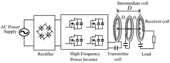
Figure 1.
The structure of an MCR-WPT system with a single-intermediate coil.
The system can be expressed with the equivalent circuit model, and Figure 2 shows the equivalent circuit of an MCR-WPT system with an intermediate coil. In the transmitter circuit, is the RMS (Root Mean Square) value of the output voltage of the high-frequency inverter, is the internal resistance of the source, is the equivalent resistance of the transmitter coil when it is operated at high frequency, is the inductance of the transmitter coil, and is the compensation capacitance of the transmitter. In the intermediate coil circuit, is the inductance of intermediate coil-1, and is the compensation capacitance of the intermediate coil-1. In the receiver circuit, is the equivalent resistance of the intermediate coil-1 when it is operated at high frequency, is the equivalent resistance of the receiver coil when it is operated at high frequency, is the inductance of the receiver coil, is the compensation capacitance of the receiver, and is the load resistance. , and are the mutual inductances between the transmitter coil and the intermediate coil-1, the intermediate coil-1 and the receiver coil, the transmitter coil and the receiver coil, respectively. is the angular frequency of the high-frequency inverter output.
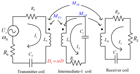
Figure 2.
The equivalent circuit model of the MCR-WPT system with a single-intermediate coil.
Based on the Kirchhoff’s voltage law (KVL), the equivalent circuit model in Figure 2 is built by
where
The resonant frequency can be expressed by
Due to the far distance, the mutual inductance between the transmitter and the receiver is small. In general, and are far greater than the non-adjacent coupling coefficient . Thus, the influence of mutual inductance on the system can be ignored. This paper assumes . Solving the KVL equation of the equivalent circuit, the current expression of each circuit can be obtained, and all the current solutions given in (4) are valid only at the resonant frequency:
where
Furthermore, the expressions of the powers of the transmitter and the receiver can be derived, respectively:
To facilitate the analysis, the distance between the transmitter coil and the intermediate coil-1 is ; the transfer distance between the transmitter and the receiver coil is D, and the distance coefficient is defined as the position of the intermediate coil-1:
On this topology, to ensure that the intermediate coil-1 is always between the transmitter coil and the receiver coil, the distance coefficient should be in the following constraint condition:
The mutual inductances are related to the distances between the coils, and the coupling coefficients are directly derived from the mutual inductances. In addition, the transfer power is related to the coupling coefficients. Thus, the transfer power is also related to the distance coefficient . The mutual inductance between the coils is shown in (9):
and are the numbers of turns of the two coil’s, and , are the radii of the two circular coils. and are the complete elliptic integrals of the first type and the second type, respectively, and is the center distance of the two round coils. The flat circular spiral coil can be considered as the overlay group of several single-turn coaxial rings with different radii on the same plane [24]. Similarly, the mutual inductance between two spiral coils can be considered as the overlay group of several pairs on different planes.
The mutual inductance between the adjacent coils can be expressed as:
The mutual inductance between the coils and can be further expressed as:
The relationship between transfer power and distance coefficient can be obtained by Equations (6)–(12):
By solving the above equation, the position of the intermediate coil-1 can be decided, and then transmission power is maximized.
2.2. Equivalent Circuit Model of a Two-Intermediate Coil WPT System
Two intermediate coils have the short circuit topology. The transmission distance is longer owing to using two-intermediate coils with a high quality factor.
Figure 3 shows the structure of WPT system with a two-intermediate coil. Similar to the single-intermediate coil system, the MCR-WPT system with a two-intermediate coil can be expressed as an equivalent circuit model. Figure 4 is the equivalent circuit of MCR-WPT system with a two-intermediate coil. In the transmitter circuit, denotes the parasitic resistance of the transmitter coil when it is operated at high frequency, descibes the inductance of the transmitter, and represents the capacitance of the transmitter compensation. In the intermediate coil circuit, denotes the parasitic resistance of the intermediate-1 coil at high frequency operation, describes the inductance of the intermediate coil-1, represents the compensation capacitance of the intermediate coil-1, denotes the parasitic resistance of the intermediate coil-2 at high frequency operation, describes the inductance of the intermediate coil-2, and represents the compensation capacitance of the intermediate coil-2. In the receiver circuit, denotes the parasitic resistance of the receiver coil at high frequencies, describes the inductance of the receiver coil, represents the compensation capacitance of the receiver coil, and is the load resistance. In addition, the mutual inductance is shown in Table 1.
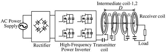
Figure 3.
The structure of the MCR-WPT system with a two-intermediate coil.
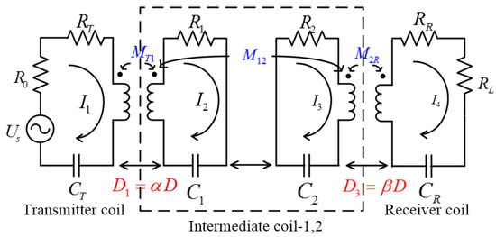
Figure 4.
The equivalent circuit of the MCR-WPT system with a two-intermediate coil.

Table 1.
Definition of mutual inductance in the equivalent circuit of a two-intermediate coil.
Since the non-adjacent coils are relatively far away from the others in practical applications, the coupling coefficients between the non-adjacent coils are weak, and the impacts on the system are very small. Therefore, in order to facilitate the calculation and analysis, similar to the analysis of the three-coil system, this paper does not consider the mutual inductance of non-adjacent coils. Thus, , , , where , , and are the mutual inductances as shown in Table 1.
Solving the current loop circuit equations, the load power is expressed as following:
where
The distance between the transmitter coil and the intermediate coil-1 is expressed as ; the distance between the intermediate coil-1 and the intermediate coil-2 as , and the distance between the intermediate coil-2 and the receiver coil as , where , , and , are defined as the distance coefficients. On this topology, the distance coefficient should satisfy the following relations:
Similar to the analysis of a single-intermediate coil MCR-WPT system, a similar mathematical formula can be obtained:
By solving the above equation, the distance coefficient and values for which the output power of the system is maximized would be obtained; this implies where the intermediate coils should be placed.
3. Simulation of an MCR-WPT System with Intermediate Coils
3.1. Simulation of a Single-Intermediate Coil WPT System
The transfer distance between the transmitter and the receiver is defined as D. The distance between the transmitter coil and the intermediate coil-1 and is , , , where is called the distance coefficient. When the transfer distance changes from 0.1 m to 0.3 m by the step of 0.1 m, the influence of the distance coefficient is simulated for the transferred power of the system. The inductance and capacitor values in Table 2, which are measured by the network analyzer, are used in the simulations, in order to compare with the experiment. The values of inductances and capacitors parameters in Table 2, which are measured by the network analyzer, are used in simulation to match with the experiment. (The is 24 V and the load is 5 Ω). The relationship curves between the transfer power and the distance coefficient is presented in Figure 5.
Table 2.
System parameters.
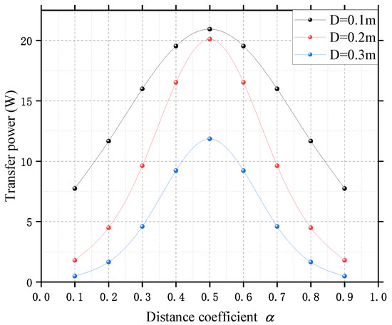
Figure 5.
The transfer power of the system under different transfer distances.
As shown in Figure 5, for the different transfer distances, the single-intermediate coil system works on the maximum transfer power condition, only when this coil is placed at a distance coefficient .
3.2. Simulation of a Two-Intermediate Coil WPT System
Through the simulations, the relationship between transfer power and distance coefficient is obtained. As shown in Figure 6, MCR-WPT systems with a two-intermediate coils reach a maximum transfer power point, when . (The is 50 V and the load is 50 Ω). In other words, when the transmitter and the receiver coil are placed symmetrically, the system obtains the maximum transfer power. At the same time, it is found that two-intermediate coils and single-intermediate coils are not exactly the same. For a single-intermediate coil system, when the intermediate coil is located in the midpoint between the transfer and the receiver coil, the load obtains the maximum power, while, in the two-intermediate coil system, the load gets the maximum power, when the two-intermediate coils are not equidistantly placed, the distances between each coils are approximately:
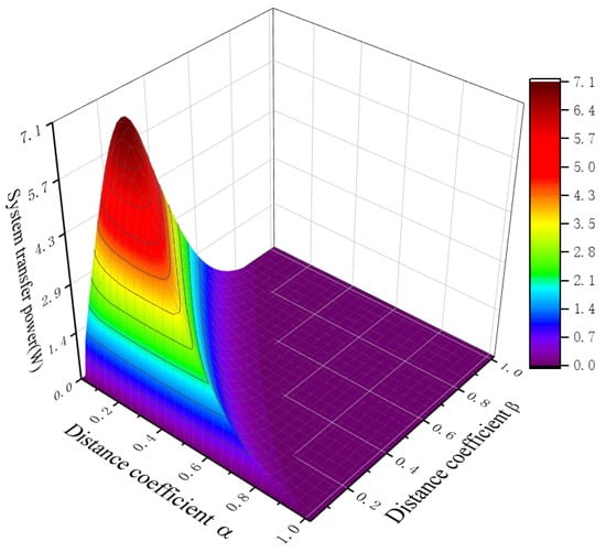
Figure 6.
Relationship between transfer power and distance coefficient , of a two-intermediate coil MCR-WPT system.
This result implies that, when the number of intermediate coil is changed, the value of the distance coefficient that maximizes the transferred power of these systems is not regular. From the transfer power expression that the output power is not only related to the mutual inductance between the coils, i.e., the distance, but also related to the load. Therefore, according to the above idea, when the load of the system is determined, the distance between the coil that maximizes the transmission power of the load is uniquely determined.
4. Experimental Verification and Analysis
4.1. The Structure of a Coil
In a MCR-WPT system, the coil of a planar spiral type is often used, owing to the magnetic field generated by the planar spiral coil is relatively uniform. In this paper, the coil’s structure is planar, circular, and spiral, where the inner diameter is 140 mm, the outer diameter is 300 mm, the spacing interval between each ring is 7.5 mm, and the number of coil turns is 8, while the diameter of the conductor copper wire is 2.5 mm. The rendering-graph and photograph of the coil is shown in Figure 7. The inductance of this coil is 17.322 H calculated according to [25]. When the compensated capacitance is 0.22 nF, the resonant frequency, which is provided with the inductance and capacitance mentioned above, is 81.3 KHz.
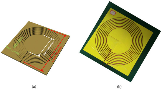
Figure 7.
(a) the rendering-graph of coil; (b) the photograph of coil.
4.2. Experimental Results Using a Network Analyzer
Figure 8 is the photograph of the experimental topology using a Network Analyzer. The values of the capacitance and inductance are measured by the network analyzer (Agilent E5061B; Cary, NC, USA), to accurately determine the resonance frequency of the system. The detailed parameters of inductances and capacitances are shown in Table 2.
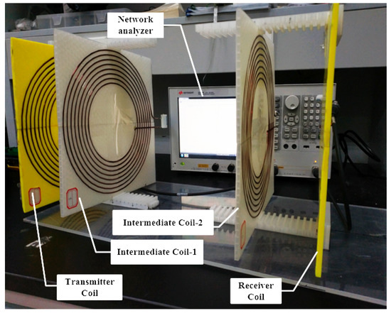
Figure 8.
Parameters were measured by a network analyzer.
In addition to accurately measuring the coil inductance and capacitance values used in the experimental platform, the frequency characteristics of the four coil resonant circuits used in the experiment are analyzed through the frequency sweeping function of the network analyzer. In addition, the Smith chart for each circuit is then shown in Figure 9. The transmitter coil, intermediate coil-1, intermediate coil-2 and receiver coil resonant circuits are scanned in the range of 50 KHz–400 KHz (because the resonance frequency is estimated to be 81.3 KHz). Each coil and compensation capacitance are connected to the network analyzer probe in series to adjust those resonances, and then, at the resonant frequency, the impedance of the resonant circuit should be close to 0. Based on the experimental results, 81.3 KHz is determined as the resonant frequency of the system.
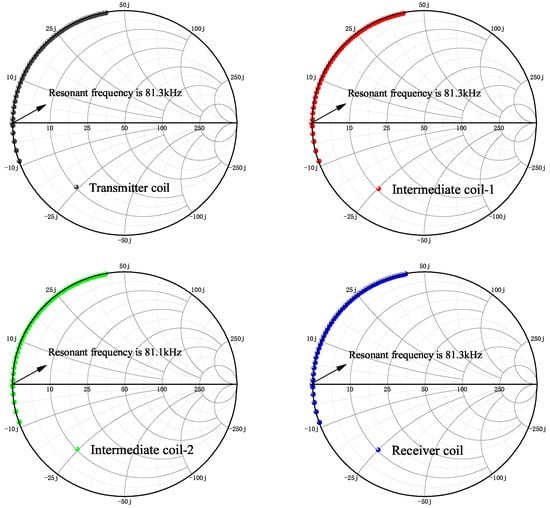
Figure 9.
The Smith chart of each resonant circuit in the range of 50 KHz–400 KHz.
As shown in Figure 8, the parameters of the system are measured by the network analyzer in the different intermediate coils’ position. The magnitude of parameters is often used to imply the transfer power of the WPT system [26].
The tendency of in a four-coil MCR-WPT system is illustrated in Figure 10, when the distance coefficient: = = 0.25. pointed with maker-1 is the value where the sweeping frequency is 81.3 KHz. Table 3 gives the parameter values for the several typical distance coefficients between the adjacent coils, including the distance ratios as shown in Figure 10. From Table 3, it is obtained that the best distance ratio between the adjacent coils in order to transfer maximum power should be 0.15:0.7:0.15 (approximately 1:5:1).
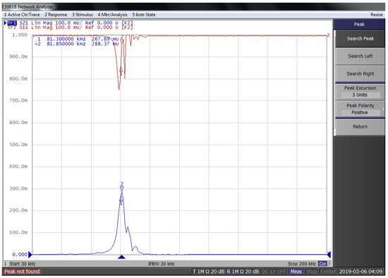
Figure 10.
The curve of the four-coil MCR-WPT system , when = = 0.25.
Table 3.
The parameters of the MCR-WPT system with intermediate coil-1, when the transfer distance D = 0.5 m.
Since each interval space of the test platform is 1 cm, the distance ratio value cannot be accurately matched with 0.15:0.75:0.15 (7.5:35:7.5). Due to the same reason, the distance for the different distance ratios between the coils should be integers at the centimeter unit, which are calculated with the rounding method. From Table 3, the position of the maximum value should be between the ratios of 8:34:8 and 7:36:7, which is consistent with the results obtained by the simulation.
4.3. Experimental Results Using the Proposed Prototype
In addition to measuring the parameters with the network analyzer, the high power platform as shown in Figure 11 is used to verify the correctness of the optimal assign method for coil distances in the three-coil and four-coil prototype. In the adjustable rectifier, 220V-50 Hz AC (Alternating Current) is converted to DC(Direct Current) 24-50 V. In the power inverter, the high frequency power that has same frequency as resonance is inverted from DC 24-50 V, and then provided to the MCR-WPT system. The high frequency power is transmitted from the transmitting coil to the receiving coil, through intermediate coil-1 and intermediate coil-2. In the experimental prototype system, the power frequency is 81.3 KHz.
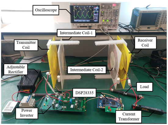
Figure 11.
Experimental prototype of the MCR-WPT system with two intermediate coils.
The load power is given in Figure 12 at the different transfer coefficient, when the transfer distances are D = 0.1 m, 0.2 m and 0.3 m. It is observed that, for any transfer distance, the measured values are approximately closed to the calculated ones, while the maximum load power always happens at mid-point i.e., the distance coefficient = 0.5.
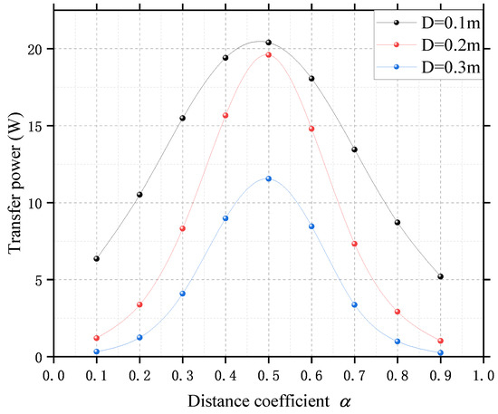
Figure 12.
Experimental results of the MCR-WPT system with the intermediate coil-1.
In addition, a group of experimental results is shown in Figure 13. The yellow curve is the voltage across the output terminal of power inverter, the green curve is the current flowing through the load connected in series with the receiving coil, and the FFT analysis is performed for the current waveform of the load as shown in Figure 14. From the FFT analysis, it is found that the constituents of (third-harmonic wave) and (fifth-harmonic wave) are small, which means that the power quality of the load is very high. This implies that the transmitter resonance circuit, two intermediate resonance circuits, and the receiver resonance circuit are with multiple filtering effects. The experimental results are shown in Table 4.
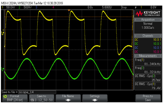
Figure 13.
Experimental result of the MCR-WPT system with two intermediate coils—when , and the transfer distance is 0.5 m.
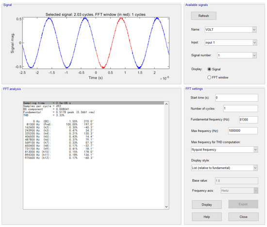
Figure 14.
Experimental result of the MCR-WPT system with two intermediate coils—when , and the transfer distance is 0.5 m.
Table 4.
The experimental results of the MCR-WPT system with intermediate coil-1,-2, when the transfer distance D = 0.5 m and the = 50 Ω.
According to Table 4, the relationship between the load power and the distance coefficients and is as shown in Figure 15, and the overall trend is similar to the simulation results as shown in Figure 6. The deviation at the maximum power point is 5.14%, and this part of the power loss is mainly consumed on the MOSFET(Metal-Oxide-Semiconductor Field-Effect Transistor) and the internal resistance of intermediate coils. The experimental results are basically consistent with the previous analysis and design.
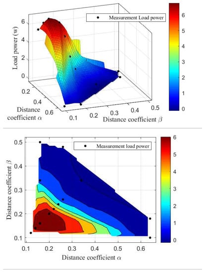
Figure 15.
Relationship between transfer power and the distance coefficient , of the two-intermediate coil MCR-WPT system.
The load obtains the maximum power when the RMS value of the load side current is the largest, and the distance coefficient between the coils of such case is between 8:34:8 and 7:36:7 as listed in Table 4. In addition to typical pairs, the same experiment is performed for the random pairs, in order to identify the correctness of the proposed method. The experimental results show that, whatever the distance ratios between the coils are, the load power on these cases is not larger than one on the ratio obtained in the paper.
5. Conclusions
The modeling for the three and four-coil MCR-WPT system is provided. The model of the coaxial planar circular spiral four-coil MCR-WPT system is followed, and then based on this model, the output power is calculated in the relationship with the distance ratios between the adjacent coils, using simulation calculation. According to this relationship, this paper proposes an optimal position configuration method for the MCR-WPT system with four coaxial plane circular spiral coils.
At the same time, the detailed parameters of the coil inductance and capacitance used in the experimental platform are illustrated in both geometrical and electrical aspects. In addition, the correctness of the simulation analysis is verified not only by using the parameters measured with the network analyzer, but also by using the load current of the experimental platform that is designed for the actual application. Finally, the waveform analysis for the load current is noted in harmonic view.
Author Contributions
All authors have cooperated in the preparation of this work. Conceptualization, J.T. and D.Y.; methodology, J.T. and D.Y.; software, J.T. and S.W.; validation, J.T., S.W. and Z.C.; formal analysis, J.T.; resources, D.Y.; writing—original draft preparation, J.T.; writing—review and editing, Z.C., B.Z. and B.H.; visualization, D.Y.; project administration, D.Y.
Funding
This research was funded by National Natural Science Foundation of China, Grant No. 61703081, the Natural Science Foundation of Liaoning Province, Grant No. 20170520113, and the State Key Laboratory of Alternate Electrical Power System with Renewable Energy Sources, Grant No. LAPS19005.
Conflicts of Interest
The authors declare no conflict of interest.
References
- Karalis, A.; Joannopoulos, J.D.; Soljačić, M. Efficient Wireless Non-radiative Mid-Range Energy Transfer. Ann. Phys. 2008, 323, 34–48. [Google Scholar] [CrossRef]
- Kurs, A.; Karalis, A.; Moffatt, R.; Joannopoulos, J.D.; Fisher, P.; Soljačić, M. Wireless Power Transfer via Strongly Coupled Magnetic Resonances. Science 2007, 317, 83–86. [Google Scholar] [CrossRef]
- Sun, G.; Muneer, B.; Li, Y.; Zhu, Q. Ultracompact Implantable Design With Integrated Wireless Power Transfer and RF Transmission Capabilities. IEEE Trans. Biomed. Circuits Syst. 2018, 12, 281–291. [Google Scholar] [CrossRef]
- Machnoor, M.; Rodríguez, E.S.G.; Kosta, P.; Stang, J.; Lazzi, G. Analysis and Design of a 3-Coil Wireless Power Transmission System for Biomedical Applications. IEEE Trans. Antennas Propag. 2019, 67, 5012–5024. [Google Scholar] [CrossRef]
- Moon, S.; Moon, G.W. Wireless Power Transfer System With an Asymmetric Four-Coil Resonator for Electric Vehicle Battery Chargers. IEEE Trans. Power Electron. 2016, 31, 6844–6854. [Google Scholar]
- Cheng, C.; Lu, F.; Zhou, Z.; Li, W.; Zhu, C.; Zhang, H.; Deng, Z.; Chen, X.; Mi, C. Load-Independent Wireless Power Transfer System for Multiple Loads Over a Long Distance. IEEE Trans. Power Electron. 2019, 34, 9279–9288. [Google Scholar] [CrossRef]
- Zhang, X.Y.; Xue, C.; Lin, J. Distance-Insensitive Wireless Power Transfer Using Mixed Electric and Magnetic Coupling for Frequency Splitting Suppression. IEEE Trans. Microw. Theory Tech. 2017, 65, 4307–4316. [Google Scholar] [CrossRef]
- Zhang, J.; Yuan, X.; Wang, C.; He, Y. Comparative Analysis of Two-Coil and Three-Coil Structures for Wireless Power Transfer. IEEE Trans. Power Electron. 2017, 32, 341–352. [Google Scholar] [CrossRef]
- Yu, H.; Zhang, G.; Jing, L.; Liu, Q.; Yuan, W.; Liu, Z.; Feng, X. Wireless Power Transfer With HTS Transmitting and Relaying Coils. IEEE Trans. Appl. Supercond. 2015, 25, 1–5. [Google Scholar] [CrossRef]
- Zhu, G.; Gao, D. Effects of intermediate coil on power transfer capability and efficiency in three-coil wireless power transfer system. In Proceedings of the 2017 IEEE Transportation Electrification Conference and Expo, Asia-Pacific (ITEC Asia-Pacific), Harbin, China, 2–5 August 2017; pp. 1–6. [Google Scholar]
- Moon, S.; Kim, B.C.; Cho, S.Y.; Ahn, C.H.; Moon, G.W. Analysis and Design of a Wireless Power Transfer System With an Intermediate Coil for High Efficiency. IEEE Transa. Ind. Electron. 2014, 61, 5861–5870. [Google Scholar] [CrossRef]
- Liu, X.; Wang, G. A Novel Wireless Power Transfer System With Double Intermediate Resonant Coils. IEEE Trans. Ind. Electron. 2016, 63, 2174–2180. [Google Scholar] [CrossRef]
- Yang, D.; Won, S.; Hong, H. Design of Range Adaptive Wireless Power Transfer System Using Non-coaxial Coils. In Proceedings of the 2nd Asia Conference on Power and Electrical Engineering (ACPEE), Shanghai, China, 24–26 March 2017. [Google Scholar]
- Luo, S.; Li, S.; Zhao, H. Reactive power comparison of four-coil, LCC and CLC compensation network for wireless power transfer. In Proceedings of the 2017 IEEE PELS Workshop on Emerging Technologies: Wireless Power Transfer (WoW), Chongqing, China, 20–22 May 2017; pp. 268–271. [Google Scholar]
- Liu, C.; Ge, S.; Guo, Y.; Li, H.; Cai, G. Double-LCL resonant compensation network for electric vehicles wireless power transfer: Experimental study and analysis. IET Power Electron. 2016, 9, 2262–2270. [Google Scholar] [CrossRef]
- Huang, S.; Li, Z.; Lu, K. Frequency splitting suppression method for four-coil wireless power transfer system. IET Power Electron. 2016, 9, 2859–2864. [Google Scholar] [CrossRef]
- Narayanamoorthi, R.; Vimala Juliet, A.; Chokkalingam, B. Cross Interference Minimization and Simultaneous Wireless Power Transfer to Multiple Frequency Loads Using Frequency Bifurcation Approach. IEEE Trans. Power Electron. 2019, 34, 10898–10909. [Google Scholar] [CrossRef]
- Varghese, B.J.; Bobba, P.B.; Kavitha, M. Effects of coil misalignment in a four coil implantable wireless power transfer system. In Proceedings of the 2016 IEEE 7th Power India International Conference (PIICON), Bikaner, India, 25–27 November 2016; pp. 1–6. [Google Scholar]
- Yang, C.L.; Chang, C.K.; Lee, S.Y.; Chang, S.J.; Chiou, L.Y. Efficient Four-Coil Wireless Power Transfer for Deep Brain Stimulation. IEEE Trans. Microw. Theory Tech. 2017, 65, 2496–2507. [Google Scholar] [CrossRef]
- Tan, L.; Guo, J.; Huang, X.; Wen, F. Output power stabilisation of wireless power transfer system with multiple transmitters. IET Power Electron. 2016, 9, 1374–1380. [Google Scholar] [CrossRef]
- Dai, Z.; Fang, Z.; Huang, H.; He, Y.; Wang, J. Selective Omnidirectional Magnetic Resonant Coupling Wireless Power Transfer With Multiple-Receiver System. IEEE Access. 2018, 6, 19287–19294. [Google Scholar] [CrossRef]
- Arakawa, T.; Goguri, S.; Krogmeier, J.V.; Kruger, A.; Love, D.J.; Mudumbai, R.; Swabey, M.A. Optimizing Wireless Power Transfer From Multiple Transmit Coils. IEEE Access. 2018, 6, 23828–23838. [Google Scholar] [CrossRef]
- Wang, W.; Wang, H.; Li, Q.; Xu, J.; Meng, T.; Zhang, B.; Zhang, Z. Analysis and Compensation of Incomplete Coupling for Omnidirectional Wireless Power Transfer. Energies 2019, 12, 3277. [Google Scholar] [CrossRef]
- Zierhofer, C.M.; Hochmair, E.S. Geometric approach for coupling enhancement of magnetically coupled coils. IEEE Trans. Biomed. Eng. 1996, 43, 708–714. [Google Scholar] [CrossRef]
- Wheeler, H.A. Simple Inductance Formulas for Radio Coils. Proc. Instit. Radio Eng. 1928, 16, 1398–1400. [Google Scholar] [CrossRef]
- Hui, S.Y.R.; Zhong, W.; Lee, C.K. A Critical Review of Recent Progress in Mid-Range Wireless Power Transfer. IEEE Trans. Power Electron. 2014, 29, 4500–4511. [Google Scholar] [CrossRef]
© 2019 by the authors. Licensee MDPI, Basel, Switzerland. This article is an open access article distributed under the terms and conditions of the Creative Commons Attribution (CC BY) license (http://creativecommons.org/licenses/by/4.0/).