Flue Gas Desulphurization in Circulating Fluidized Beds

Abstract
1. Introduction
1.1. An Overiew of the Sulphur Problem
1.2. Review of De-SO2 Techniques
1.3. Objectives and Novelties of the Present Researach
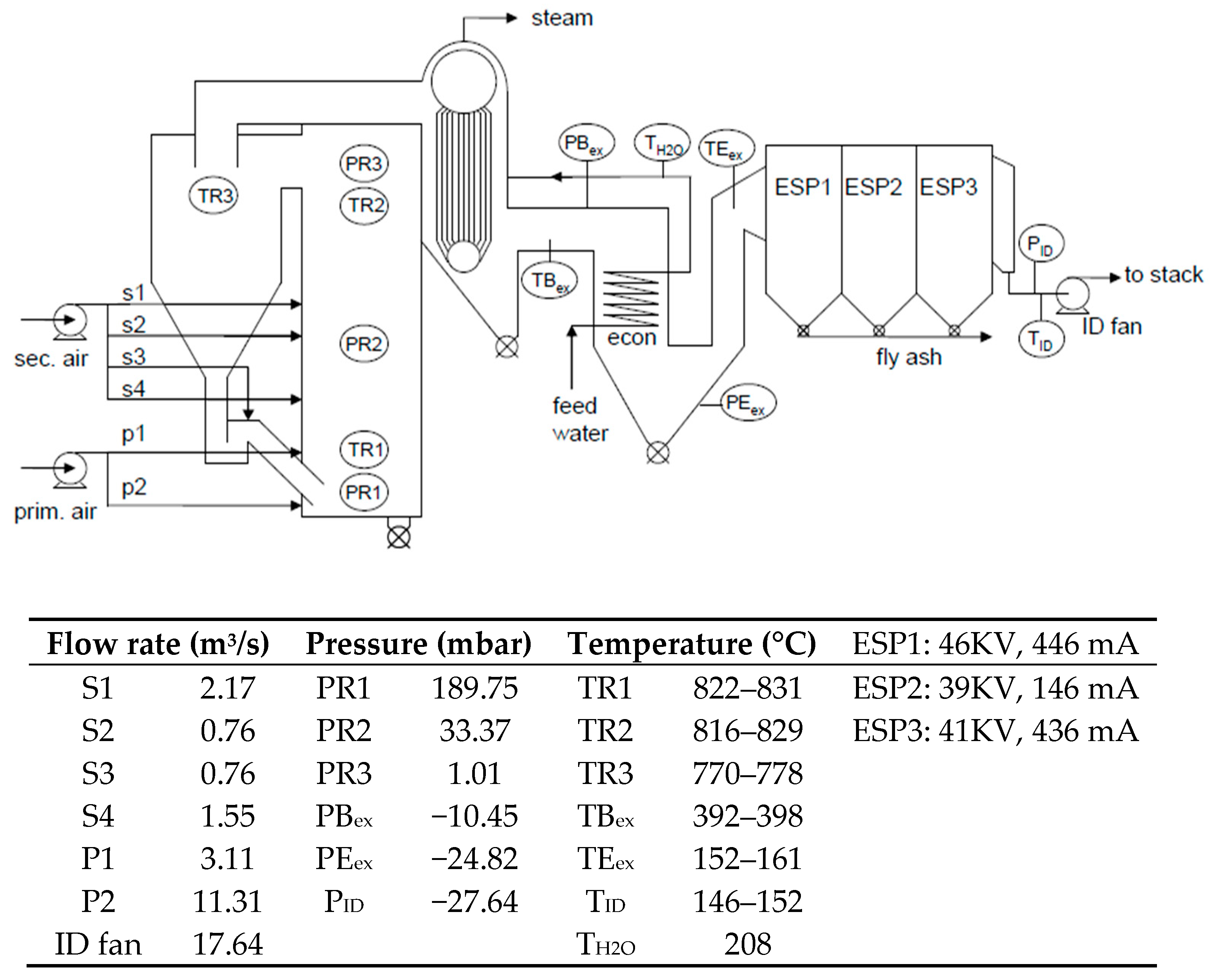
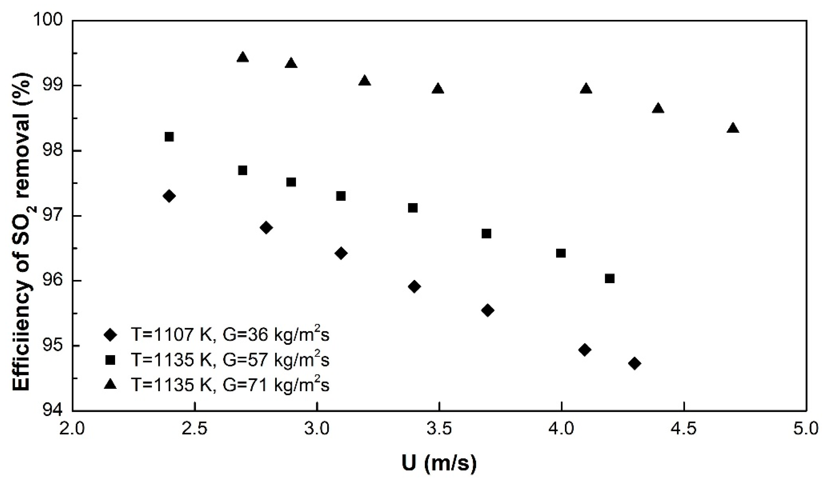
2. Experimental Set-Up and Results
3. Development of a General Gas-Solid Model for SO2 Capture
3.1. Model Equations
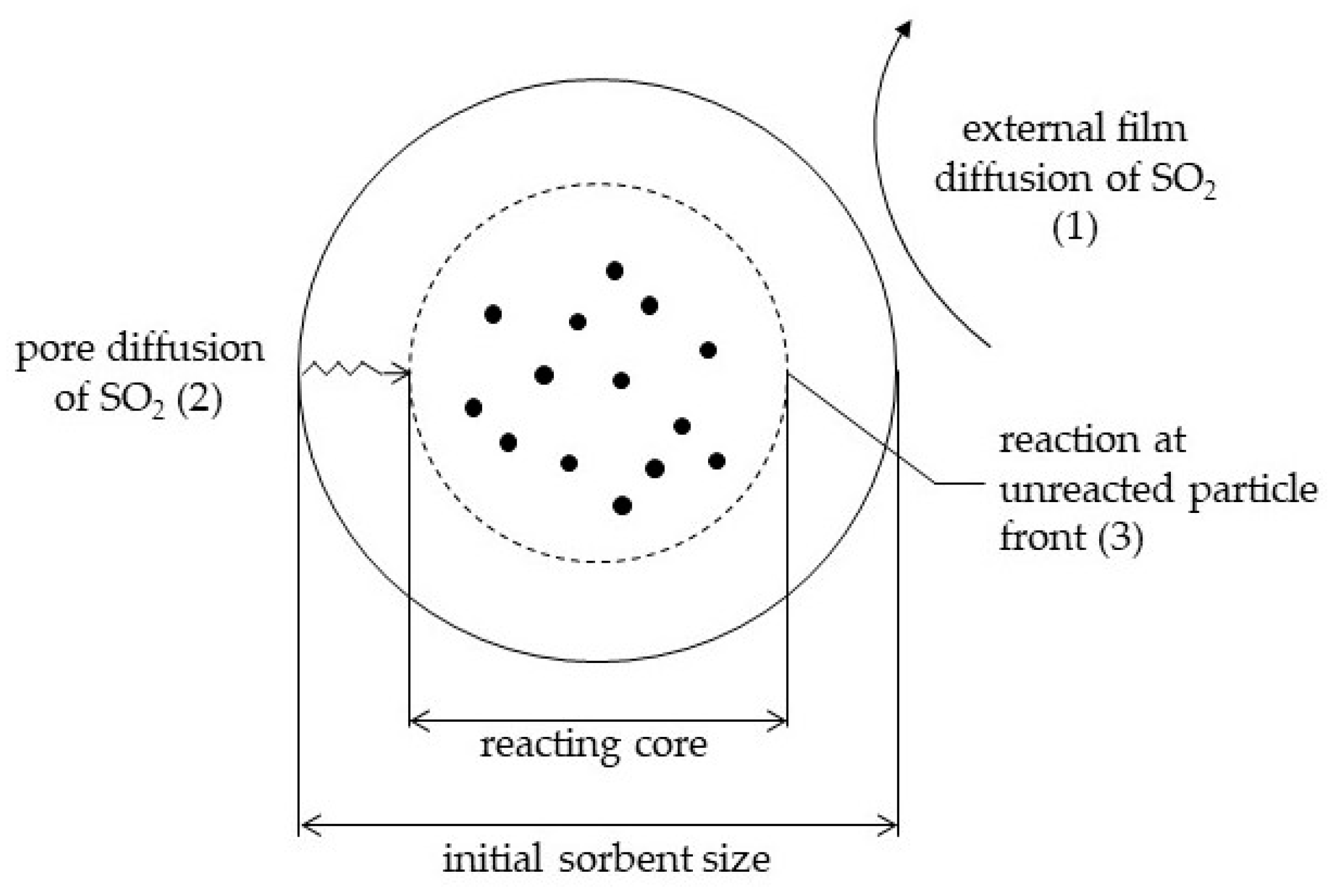
- The external diffusion of SO2 across the gas film, determined by the Sherwood number, and a function of the turbulence of the system and therefore of the type of reactor;
- The internal diffusion of SO2 in the porous particles, expected to play a role in particles of large diameter, only;
- The reaction as such (1st order), function of the reaction rate constant and the contact time.
3.2. Evaluation of the Model Parameters
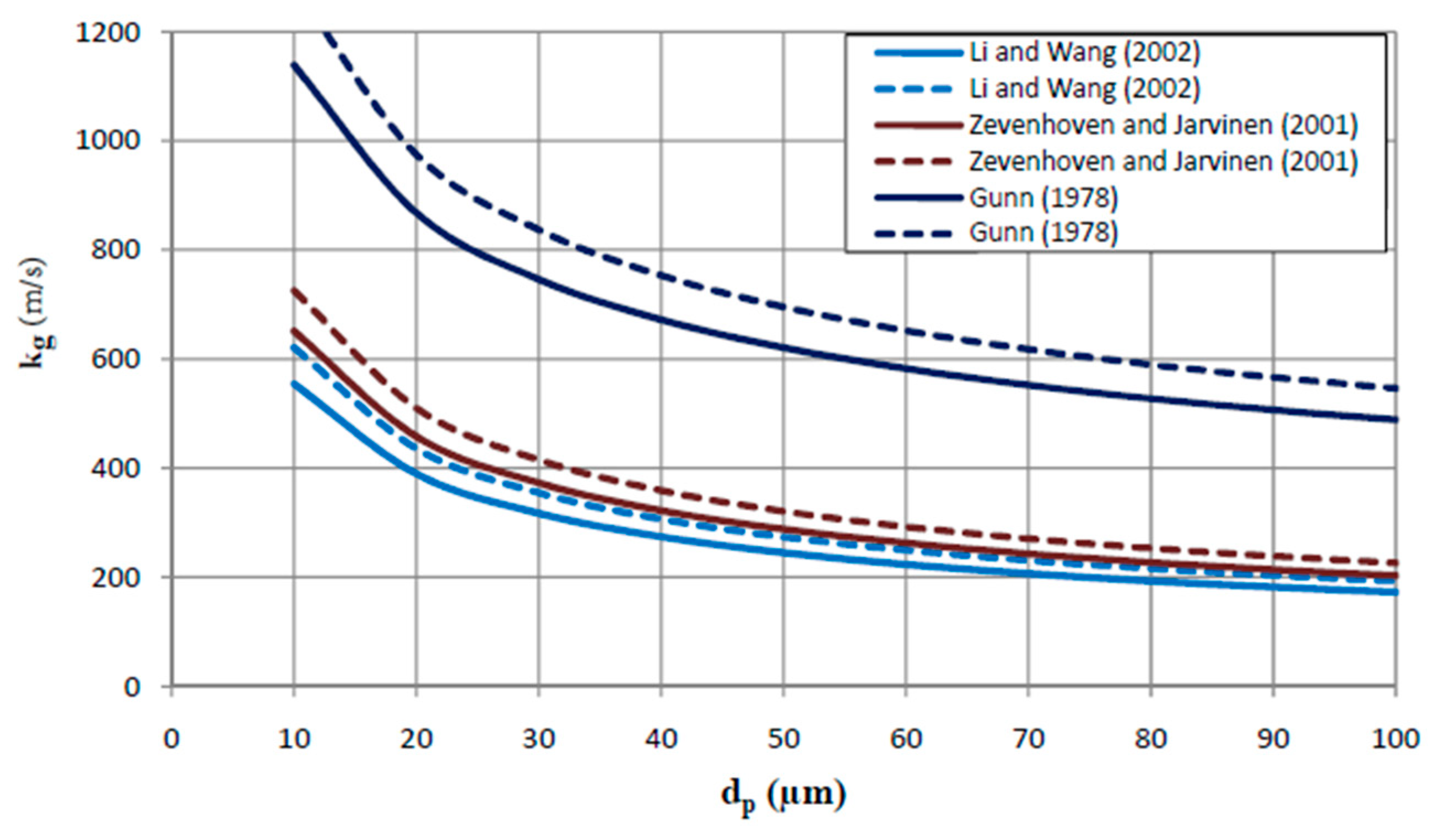
3.2.1. External Diffusion
| Sh, Sherwood number, kgdp/Dg | (-) |
| Re, Reynolds number, dpUslρg/μg | (-) |
| Sc, Schmidt number, μg /ρg Dg | (-) |
| Dg, Diffusivity of SO2 in the gas flow | (m2/s) |
| dp, Particle diameter | (m) |
| kg, Gas film mass transfer coefficient | (m/s) |
| Usl, Slip velocity (i.e., ~ U-Ut) | (m/s) |
| U, Superficial gas velocity in the CFB | (m/s) |
| Ut, Particle terminal velocity | (m/s) |
| , Gas viscosity | (Pa.s) |
| , Gas density | (kg/m3) |
3.2.2. The Effective Internal Diffusion Coefficient, De
3.2.3. The Reaction Rate Constant, kc
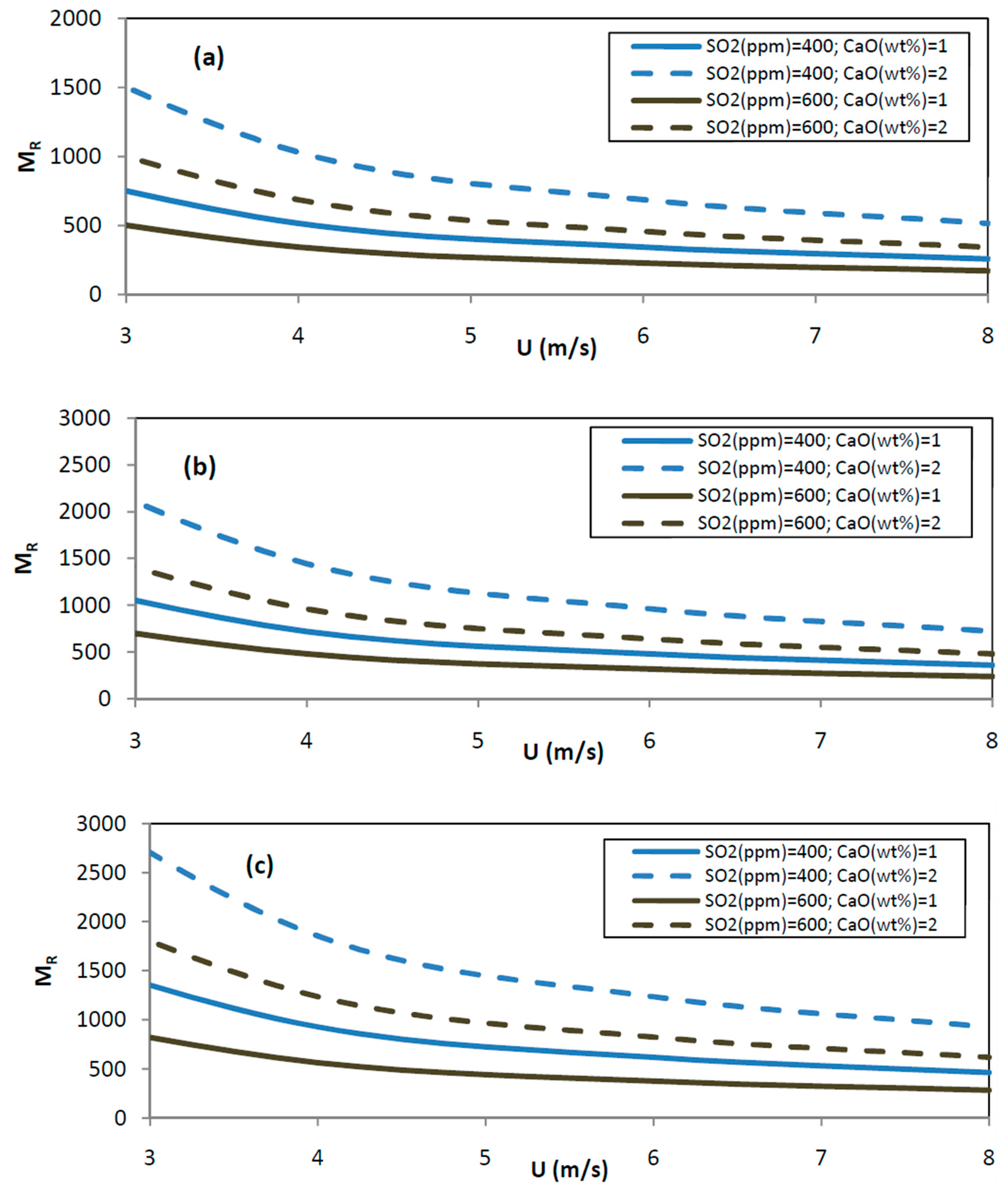
3.2.4. The Molar Ratio MR (Expressed as Ca/S or CaO/S)
| G, Solid circulation flux | (kg/m2s) |
| A, Cross sectional area of the riser | (m2) |
| MMCaCO3, molecular weight of CaCO3 | 100 kg/kmol |
| MMCaO, molecular weight of CaO | 56 kg/kmol |
| %CaCO3/%CaO, weight percentage in G | - |
3.2.5. Evaluation of the Model Parameters
- De: 10−7 to 10−9 m2/s, commonly adopted as 10−9 m2/s
- kg: Allowing for a safety margin, kg is taken at a conservative average of 300 m/s, for the particle size range (<74 μm) under scrutiny
- kc: 5 × 10⁻² m/s
- The MR ratio is calculated according to the equations before, and illustrated in Figure 8.
- The residence time distribution of the gas phase in the riser of a CFB was studied by [39]. The average contact time is given by:= 0.54(U-UTR)−0.25G−0.2H with in s and H, the riser height in m (19)
4. Application of the Model Equations and Comparison with Experimental Result
4.1. Effect of Contact Mode
4.2. The CFB Contact Mode
5. Conclusions
Author Contributions
Funding
Acknowledgments
Conflicts of Interest
Nomenclature
| A | Cross sectional area of the riser | m2 |
| C | Dimensionless gas reactant concentration | - |
| Cg0 | Initial gas concentration | mol/m3 |
| Cg | Gas concentration at any time | mol/m3 |
| dp | Particle diameter | m |
| D | Diameter of riser | m |
| De | Effective Diffusivity of SO2 in the porous reagent | m2/s |
| Dg | Diffusivity of SO2 in the gas flow | m2/s |
| H | Height of the riser | m |
| G | Solid circulation flux | kg/m2s |
| gi | Reaction rate parameters defined by Equations (9) to (12) | - |
| kc | Reaction rate constant | m/s |
| kg | Gas film mass transfer coefficient | m/s |
| MR | Molar ratio of Ca2+-reactant and S | - |
| Ms | Molar mass of solid reagent (CaO) | g/mol |
| MM | molecular weight | kg/kmol |
| MV | molar volume | Nm3/kmol |
| P | Pressure | Pa |
| rc | Radius of the reaction boundary | m |
| R0 | Initial radius | m |
| T | Temperature | K |
| t | Reaction time | s |
| Average contact time in CFB | s | |
| U | Superficial gas velocity in the CFB | m/s |
| Usl | Slip velocity (i.e., ~ U-Ut) | m/s |
| Ut | Terminal velocity of particle | m/s |
| UTR | Transport velocity | m/s |
| X | Fractional conversion | - |
| Greek letters | ||
| ρg | Gas density | kg/m3 |
| ρp | Particle density | kg/m3 |
| μg | Gas viscosity | Pa·s |
| τ | Dimensionless time | - |
| ε | Voidage in the riser | - |
| φi | Reaction rate parameters defined by Equations (13) to (15) | - |
Abbreviations
| A.P.I | American Petroleum Institute |
| BFB | Bubbling fluidized bed |
| Bi | Biot number, kgR0/De |
| CFB | Circulating fluidized bed |
| CFBC | Circulating fluidized bed combustor |
| Da | Damkohler number, kcR0/De |
| deSO2 | SO2 Removal |
| EBFT | Electron beam flue gas treatment |
| FGD | Flue gas desulphurisation |
| Re | Reynolds number, dpUslρg/μg |
| Sc | Schmidt number, μg/ρg Dg |
| Sh | Sherwood number, kg/dp Dg |
References
- IEA. CO2 Emissions from Fuel Combustion; OECD iLibrary: Marrakesh, Morocco, 2016; ISBN 9789264258563. [Google Scholar] [CrossRef]
- Quéré, C.; Andrew, R.; Friedlingstein, P.; Sitch, S.; Hauck, J.; Pongratz, J.; Pickers, P.; Ivar Korsbakken, J.; Peters, G.; Canadell, J.; et al. Global Carbon Budget 2018. Earth Syst. Sci. Data 2018, 10, 2141–2194. [Google Scholar] [CrossRef]
- Mahmoudi, S.; Baeyens, J.; Seville, J.P. NOx formation and selective non-catalytic reduction (SNCR) in a fluidized bed combustor of biomass. Biomass Bioenergy 2010, 34, 1393–1409. [Google Scholar] [CrossRef]
- Urone, P. The primary air pollutants—Gaseous. Their occurrence, sources, and effects. In Air Pollution; Stern, A.C., Ed.; Academic Press: New York, NY, USA, 1976; Volume 1. [Google Scholar]
- Gibeaux, S.; Thomachot-Schneider, C.; Eyssautier-Chuine, S.; Marin, B.; Vázquez, P. Simulation of acid weathering on natural and artificial building stones according to the current atmospheric SO2/NOx rate. Environ. Earth Sci. 2018, 77, 327. [Google Scholar] [CrossRef]
- Oruc, O.; Dincer, I. Environmental impact assessment of using various fuels in a thermal power plant. Int. J. Glob. Warm. 2019, 18, 191–205. [Google Scholar] [CrossRef]
- Carnell, E.; Vieno, M.; Vardoulakis, S.; Beck, R.; Heaviside, C.; Tomlinson, S.; Dragosits, U.; Heal, M.; Reis, S. Modelling public health improvements as a result of air pollution control policies in the UK over four decades—1970 to 2010. Environ. Res. Lett. 2019. [Google Scholar] [CrossRef]
- Amsalu, E.; Guo, Y.; Li, H.; Wang, T.; Liu, Y.; Wang, A.; Liu, X.; Tao, L.; Luo, Y.; Zhang, F.; et al. Short-term effect of ambient sulfur dioxide (SO2) on cause-specific cardiovascular hospital admission in Beijing, China: A time series study. Atmos. Environ. 2019, 208, 74–81. [Google Scholar] [CrossRef]
- Wang, H.; Yuan, B.; Hao, R.; Zhao, Y.; Wang, X. A critical review on the method of simultaneous removal of multi-air-pollutant in flue gas. Chem. Eng. J. 2019, 378, 122155. [Google Scholar] [CrossRef]
- Tao, L.; Wang, X.; Ning, P.; Wang, L.; Fan, W. Removing sulfur dioxide from smelting flue and increasing resource utilization of copper tailing through the liquid catalytic oxidation. Fuel Process. Technol. 2019, 192, 36–44. [Google Scholar] [CrossRef]
- Iliuta, I.; Iliuta, M.C. Modeling of SO2 seawater scrubbing in countercurrent packed-bed columns with high performance packings. Sep. Purif. Technol. 2019, 226, 162–180. [Google Scholar] [CrossRef]
- He, J.; Zhang, J.; Shang, H. Dynamic modelling and simulation of the sulphur dioxide converter in an industrial smelter. Can. J. Chem. Eng. 2019, 97, 1838–1847. [Google Scholar] [CrossRef]
- Nurrohim, A.; Sakugawa, H. Fuel-based inventory of NOx and SO2 emissions from motor vehicles in the Hiroshima Prefecture, Japan. Appl. Energy 2005, 80, 291–305. [Google Scholar] [CrossRef]
- Ma, X.; Kaneko, T.; Tashimo, T.; Yoshida, T.; Kato, K. Use of Limestone for SO2 Removal from Flue Gas in the Semidry FGD Process with a Powder-Particle Spouted Bed. Chem. Eng. Sci. 2000, 55, 4643–4652. [Google Scholar] [CrossRef]
- Moeini, M.; Hatamipour, M.S. Flue Gas Desulfurization by a Powder-Particle Spouted Bed. Chem. Eng. Technol. 2008, 31, 71–82. [Google Scholar] [CrossRef]
- Backhurst, J.R.; Sinnott, R.K.; Richardson, J.F. Coulson & Richardson Chemical Engineering; Butterworth-Heinemann: Oxford, UK, 2001; pp. 105–107. [Google Scholar]
- Selmeczi, J.G.; Stewart, D.A. Flue gas desulfurization/The Dravo Corp. Thiosorbic flue gas desulfurization process. Chem. Eng. Prog. 1978, 74, 2. [Google Scholar]
- Benson, L. Development and Commercialization of the Thiosorbic Lime Wet Scrubbing Process for Flue Gas Desulfurization. In Lime for Environmental Uses; ASTM International: West Conshohocken, PA, USA, 1987; pp. 20–31. [Google Scholar]
- Gutschick, K. Lime for Environmental Uses: A Symposium Sponsored by ASTM Committee C-7 on Lime, Los Angeles, CA, 25 June 1985; ASTM International: West Conshohocken, PA, USA, 1987. [Google Scholar]
- Cunic, D.; Lunt, R. Profiles in Flue Gas Desulphurization; American Institute of Chemical Engineers: New York, NY, USA, 1994. [Google Scholar]
- Medellin, P.M.; Weger, E.; Dudukovic, M.P. Removal of SO2 and NOxfrom Simulated Flue Gases by Alkalized Alumina in a Radial Flow Fixed Bed. Ind. Eng. Chem. Process. Des. Dev. 1978, 17, 528–536. [Google Scholar] [CrossRef]
- Hao, R.; Wang, X.; Mao, X.; Tian, B.; Zhao, Y.; Yuan, B.; Tao, Z.; Shen, Y. An integrated dual-reactor system for simultaneous removal of SO2 and NO: Factors assessment, reaction mechanism and application prospect. Fuel 2018, 220, 240–247. [Google Scholar] [CrossRef]
- Park, H.-W.; Uhm, S. Various technologies for simultaneous removal of NO and SO from flue gas. Appl. Chem. Eng. 2017, 28, 607–618. [Google Scholar]
- Ar, I.; Balci, S. Sulfation reaction between SO2 and limestone: Application of deactivation model. Chem. Eng. Process. Process Intensif. 2002, 41, 179–188. [Google Scholar] [CrossRef]
- Baege, R.; Sauer, H. Recent Developments in CFB-FGD Technology; VGB PowerTech: Essen, Germany, 2000. [Google Scholar]
- Basfar, A.; Fageeha, O.; Kunnummal, N.; Al-Ghamdi, S.; Chmielewski, A.G.; Licki, J.; Pawelec, A.; Tymiński, B.; Zimek, Z. Electron beam flue gas treatment (EBFGT) technology for simultaneous removal of SO2 and NOx from combustion of liquid fuels. Fuel 2008, 87, 1446–1452. [Google Scholar] [CrossRef]
- Licki, J.; Chmielewski, A.; Iller, E.; Zimek, Z.; Mazurek, J.; Sobolewski, L. Electron-beam flue-gas treatment for multicomponent air-pollution control. Appl. Energy 2003, 75, 145–154. [Google Scholar] [CrossRef]
- Zwolińska, E.; Gogulancea, V.; Sun, Y.; Lavric, V.; Chmielewski, A. A kinetic sensitivity analysis for the SO2 and NOx removal using the electron beam technology. Radiat. Phys. Chem. 2017, 138, 29–36. [Google Scholar] [CrossRef]
- Toftegaard, M.; Brix, J.; Jensen, P.; Glarborg, P.; Jensen, A.D. Oxy-fuel combustion of solid fuels. Prog. Energy Combust. Sci. 2010, 36, 581–625. [Google Scholar] [CrossRef]
- Chen, L.; Wang, C.; Si, T.; Anthony, E.J. Modelling the simultaneous calcination/sulfation behavior of limestone under circulating fluidized bed combustion conditions. Fuel 2019, 257, 116072. [Google Scholar] [CrossRef]
- Mahmoudi, S.; Chan, C.W.; Brems, A.; Seville, J.; Baeyens, J. Solids flow diagram of a CFB riser using Geldart B-type powders. Particuology 2012, 10, 51–61. [Google Scholar] [CrossRef]
- Van Caneghem, J.; Brems, A.; Lievens, P.; Block, C.; Billen, P.; Vermeulen, I.; Dewil, R.; Baeyens, J.; Vandecasteele, C. Fluidized bed waste incinerators: Design, operational and environmental issues. Prog. Energy Combust. Sci. 2012, 38, 551–582. [Google Scholar] [CrossRef]
- Van De Velden, M.; Baeyens, J.; Dougan, B.; McMurdo, A. Investigation of operational parameters for an industrial CFB combustor of coal, biomass and sludge. China Particuol. 2007, 5, 247–254. [Google Scholar] [CrossRef]
- Yi, J.; Sauer, H.; Leuschke, F.; Baege, R. What is possible to achieve on flue gas cleaning using the CFB technology. In Proceedings of the 8th International Conference on CFB, Hangzhou, China, 10–13 May 2005. [Google Scholar]
- Hollett, G.T. Dry removal of SO/sub 2: Application to industrial coal-fired boilers. Proc. Annu. Meet. Air Pollut. Control Assoc. 1979; 79. [Google Scholar]
- Sauer, H.; Porter, D.E. Dry Removal of Gaseous Pollutants from Flue Gases with the Circulating Fluid Bed Scrubber; Report C479/022; IMechE: London, UK, 20 October 1994. [Google Scholar]
- Hansen, S.K.; Toher, J.; Lanois, G.; Sauer, H. High Efficiency, Dry Flue Gas SOx and Combined SOx/NOx Removal Experience with the Lurgi Circulating Fluid Bed Dry Scrubber-a new economical retrofit option for U.S. utilities for acid rain remediation. In Proceedings of the International Power Generation Conference, San Diego, CA, USA, 1991. [Google Scholar]
- Leuschke, F.; Bleckwehl, S.; Ratschow, L.; Werther, J. Flue gas desulphurization in a circulating fluidized bed: Investigation after 10 years of successful commercial operation at the facility of Pilsen/Cz. In Proceedings of the 9th International Conference on Circulating Fluidized Beds, Hamburg, Germany, 13–16 May 2008. [Google Scholar]
- Mahmoudi, S.; Seville, J.; Baeyens, J. The residence time distribution and mixing of the gas phase in the riser of a circulating fluidized bed. Powder Technol. 2010, 203, 322–330. [Google Scholar] [CrossRef]
- Zhang, H.; Kong, W.; Tan, T.; Gilles, F.; Baeyens, J. Experiments support an improved model for particle transport in fluidized beds. Sci. Rep. 2017, 7, 10178. [Google Scholar] [CrossRef]
- Chan, C.; Seville, J.P.K.; Parker, D.J.; Baeyens, J. Particle velocities and their residence time distribution in the riser of a CFB. Powder Technol. 2010. [Google Scholar] [CrossRef]
- Dewil, R.; Baeyens, J.; Caerts, B. CFB cyclones at high temperature: Operational results and design assessment. Particuology 2008, 6, 149–156. [Google Scholar] [CrossRef]
- Zhang, H.; Degrève, J.; Baeyens, J.; Wu, S.-Y. Powder attrition in gas fluidized beds. Powder Technol. 2016, 287, 1–11. [Google Scholar] [CrossRef]
- Mahmoudi, S.; Baeyens, J.; Seville, J. The solids flow in the CFB-riser quantified by single radioactive particle tracking. Powder Technol. 2011, 211, 135–143. [Google Scholar] [CrossRef]
- Han, K.; Lu, C.; Cheng, S.; Zhao, G.; Wang, Y.; Zhao, J. Effect of characteristics of calcium-based sorbents on the sulfation kinetics. Fuel 2005, 84, 1933–1939. [Google Scholar] [CrossRef]
- Hartman, M.; Svoboda, K.; Trnka, O.; Veselý, V. Reaction of sulphur dioxide with magnesia in a fluidised bed. Chem. Eng. Sci. 1988, 43, 2045–2050. [Google Scholar] [CrossRef]
- Kunii, D.; Levenspiel, O. Fluidization Engineering; Butterworth- Heinemann: Newton, MA, USA, 1991. [Google Scholar]
- Benitez, J. Process Engineering and Design for Air Pollution Control; Prentice Hall: Englewood Cliffs, NJ, USA, 1993; Volume 8. [Google Scholar]
- Li, J.; Wang, L. Concentration distributions during mass transfer in circulating fluidized beds. In Proceedings of the 7th International Conference on Circulating Fluidized Beds, Niagara Falls, ON, Canada, 5–8 May 2002. [Google Scholar]
- Zevenhoven, R.; Järvinen, M. Particle/Turbulence Interactions, Mass Transfer and Gas/Solid Chemistry in a CFBC Riser. Flow Turbul. Combust 2001, 67, 107–124. [Google Scholar] [CrossRef]
- Gunn, D. Transfer of heat or mass to particles in fixed and fluidised beds. Int. J. Heat Mass Transf. 1978, 21, 467–476. [Google Scholar] [CrossRef]
- Van De Velden, M.; Baeyens, J.; Brems, A.; Janssens, B.; Dewil, R. Fundamentals, kinetics and endothermicity of the biomass pyrolysis reaction. Renew. Energy 2010, 35, 232–242. [Google Scholar] [CrossRef]
- Fuertes, A.B.; Velasco, G.; Fuente, E.; Alvarez, T. Study of the direct sulfation of limestone particles at high CO2 partial pressures. Fuel Process. Technol. 1994, 38, 181–192. [Google Scholar] [CrossRef]
- Zhong, Q. Direct sulfation reaction of SO2 with calcium carbonate. Thermochim. Acta 1995, 260, 125–136. [Google Scholar] [CrossRef]
- Hajaligol, M.R.; Longwell, J.P.; Sarofim, A.F. Analysis and Modeling of the Direct Sulfation of CaCO2. Ind. Eng. Chem. Res. 1988. [Google Scholar] [CrossRef]
- Iisa, K.; Hupa, M.; Yrjas, P. Product layer diffusion in the sulphation of calcium carbonate. Symp. Combust. 1992, 24, 1349–1356. [Google Scholar] [CrossRef]
- Liu, H.; Katagiri, S.; Kaneko, U.; Okazaki, K. Sulfation behavior of limestone under high CO2 concentration in O2/CO2 coal combustion. Fuel 2000, 79, 945–953. [Google Scholar] [CrossRef]
- Qiu, K.; Lindqvist, O. Direct sulfation of limestone at elevated pressures. Chem. Eng. Sci. 2000, 55, 3091–3100. [Google Scholar] [CrossRef]
- Zevenhoven, R.; Yrjas, P.; Hupa, M. Sulfur dioxide capture under PFBC conditions: The influence of sorbent particle structure. Fuel 1998, 77, 285–292. [Google Scholar] [CrossRef]
- Snow, M.J.H.; Longwell, J.P.; Sarofim, A.F. Direct sulfation of calcium carbonate. Ind. Eng. Chem. Res. 1988, 27, 268–273. [Google Scholar] [CrossRef]
- Simons, G.A.; Rawlins, W.T. Reaction of Sulfur Dioxide and Hydrogen Sulfide with Porous Calcined Limestone. Ind. Eng. Chem. Process. Des. Dev. 1980, 19, 565–572. [Google Scholar] [CrossRef]
- Borgwardt, R.H. Kinetics of the Reaction of SO2 with Calcined Limestone. Environ. Sci. Technol. 1970. [Google Scholar] [CrossRef]
- Zhang, H.; Degrève, J.; Dewil, R.; Baeyens, J. Operation Diagram of Circulating Fluidized Beds (CFBs). Procedia Eng. 2015, 102, 1092–1103. [Google Scholar] [CrossRef][Green Version]
- Zhang, H.; Degrève, J.; Baeyens, J.; Dewil, R. The Voidage in a CFB Riser as Function of Solids Flux and Gas Velocity. Procedia Eng. 2015, 102, 1112–1122. [Google Scholar] [CrossRef][Green Version]


 1023K and
  1123K.


| Parameters | Used in the Present Research | Petroleum Fuels Oil | |||||
|---|---|---|---|---|---|---|---|
| Coal (Columbia) | Wood Bark | Sludge | No.1 Fuel Oil (41.5° A.P.I.) | No.2 Fuel Oil (33° A.P.I.) | Low Sulfur (12.6° A.P.I.) | High Sulfur (15.5° A.P.I.) | |
| Ash content (wt.% dry) | 7.7–9.2 | 0.2–0.3 | 7.0–22.9 | <0.01 | <0.01 | 0.04 | 0.02 |
| C (wt.%) | 60.1–62.1 | 17.8–22.3 | 10.3–15.7 | 86.4 | 87.3 | 87.26 | 84.67 |
| H (wt.%) | 4.22–4.25 | 1.11–2.72 | 1.39–2.09 | 13.6 | 12.6 | 10.49 | 11.02 |
| S (wt.%) | 0.58–0.59 | 0.02–0.05 | 0.05–0.06 | 0.09 | 0.22 | 0.84 | 3.97 |
| N (wt.%) | 1.26–1.35 | 0.04–0.17 | 0.05–0.09 | 0.003 | 0.006 | 0.28 | 0.18 |
| O (wt.%) | 8.92–8.97 | 16.42–18.82 | 12.71–15.13 | 0.01 | 0.04 | 0.64 | 0.38 |
| Author | Methods | Characteristics |
|---|---|---|
| [14,15] | Semi-dry flue gas desulphurization (FGD) | Contact with slurry of Ca(OH)2 Production of CaSO4 (in some cases reusable in building industry) |
| [11,16] | Scrubbing (H2O) | Scrubbing with water in countercurrent adsorption tower Formation of H2SO4 Concentration to technical grade H2SO4 needed |
| [17,18,19] | Thiosorb lime wet scrubbing | Reagent of 3–6 wt% MgO acts as catalyst for SO2 removal by lime Reliable and cost-effective process for high-sulphur applications |
| [20,21,22,23] | Regenerative alumina process | Simultaneous removal of NOx and SO2 by of alumina pellets with sodium aluminates Spent sorbent is regenerated No longer used in practical applications |
| [24,25] | Dry limestone | Most practical method, using dry limestone or lime Application in fluidized beds |
| [26,27,28] | Electron beam flue gas treatment (EBFT) | Simultaneous dry removing of SO2 and NOx Flue gas irradiation with fast electrons initiating chemical reactions High capital and operating costs |
| [29] | Oxy-fuel combustion | The substitution of N2 by O2 in oxy-fuel combustion does not affect the release of sulphur from the coal during combustion. Increased retention will reduce the SO2 emission rate |
| Riser | Cyclone | ||||||
|---|---|---|---|---|---|---|---|
| Square | Total length | Length above L-valve | Diameter cylinder | Length cylinder | Length conical part | Solids apex | Gas outlet |
| 3780 mm | 18,450 mm | 14,000 mm | 4560 mm | 5460 mm | 5000 mm | 1310 mm | 1860 mm |
| Component | Pore Volume (cm3/g) | BET SUrface Area (m2/g) | Type of Porosity |
|---|---|---|---|
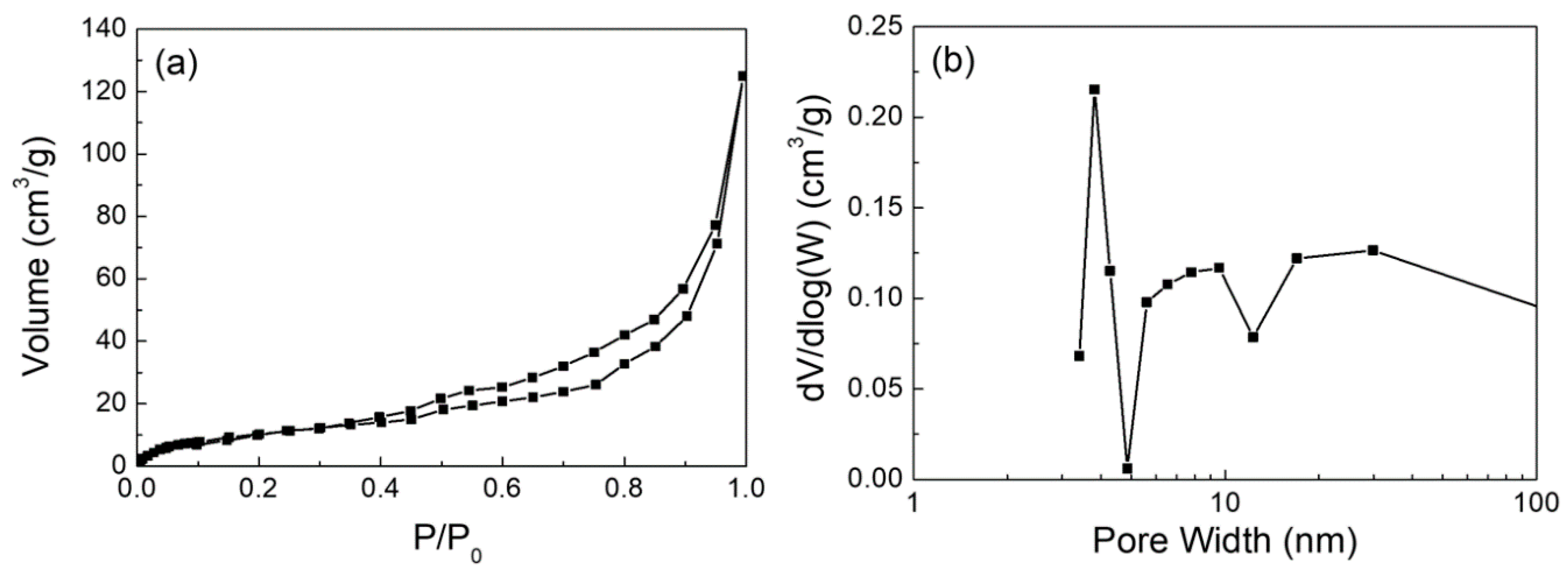
| Ca(OH)2 | 0.20 | 40.6 | Mesoporous 5–12 nm |
| Authors | T(K) | Composition | Particle Size(μm) | De (m2/s) |
|---|---|---|---|---|
| [55] | 773–1213 | SO2: 0.3%; O2: 5%; CO2: 95% | 2–106 | 7.34110−7 |
| [53] | 923–1173 | SO2: 0.25%; O2: 3.6%; CO2: 96.4% | 2–106 | 6.3410−10 |
| [54] | 1073 | SO2: 0.1%–0.5%; O2: 10%; CO2: 70% | 4–5.4 | 2.110−9 |
© 2019 by the authors. Licensee MDPI, Basel, Switzerland. This article is an open access article distributed under the terms and conditions of the Creative Commons Attribution (CC BY) license (http://creativecommons.org/licenses/by/4.0/).
Share and Cite
Deng, Y.; Ansart, R.; Baeyens, J.; Zhang, H. Flue Gas Desulphurization in Circulating Fluidized Beds. Energies 2019, 12, 3908. https://doi.org/10.3390/en12203908
Deng Y, Ansart R, Baeyens J, Zhang H. Flue Gas Desulphurization in Circulating Fluidized Beds. Energies. 2019; 12(20):3908. https://doi.org/10.3390/en12203908
Chicago/Turabian StyleDeng, Yimin, Renaud Ansart, Jan Baeyens, and Huili Zhang. 2019. "Flue Gas Desulphurization in Circulating Fluidized Beds" Energies 12, no. 20: 3908. https://doi.org/10.3390/en12203908
APA StyleDeng, Y., Ansart, R., Baeyens, J., & Zhang, H. (2019). Flue Gas Desulphurization in Circulating Fluidized Beds. Energies, 12(20), 3908. https://doi.org/10.3390/en12203908