Abstract
The maximum-torque-per-ampere (MTPA) scheme is widely used in the interior permanent magnet synchronous machine (IPMSM) drive system to reduce copper losses. However, MTPA trajectory is complicated to solve analytically. In order to realize online MTPA trajectory tracking, this paper proposes a novel torque control strategy. The torque control is designed to be closed form. Considering the machine reluctance torque as the torque feedback, when this is compared with the torque reference, then the excitation torque reference can be obtained. Since the excitation torque is proportional to the q-axis current, the q-axis current reference can be fed by the excitation torque reference through a proportional regulator. Once the q-axis current reference is given, the d-axis current reference can be calculated based on the per-unit model, which aims to simplify the calculation and make the control strategy independent of machine parameters. In this paper, the stability of the control system is demonstrated. Meanwhile, simulation and experiment results show this torque control strategy can realize MTPA trajectory tracking online and have success in transients.
1. Introduction
Due to outstanding characteristics, such as high-power density, wide speed range, and a high torque-to-inertia ratio, interior permanent magnet synchronous machines (IPMSMs) are suitable for many industrial applications [,,]. Differing from the surface permanent magnet synchronous machine (SPMSM), the IPMSM contains not only an excitation torque but also a reluctance torque. Moreover, the excitation torque is proportional to the q-axis current and the reluctance torque is relative to both d- and q-axis stator current. In general, the d-axis current reference is set to zero, and the reluctance torque is consequently null. Then, the torque of IPMSM is proportional to the q-axis current. As a result, this method is easy to implement, but inefficient. In order to improve the efficiency, the maximum-torque-per-ampere (MTPA) scheme, which aims to minimize copper losses of IPMSM during operating, is proposed [,]. Under the MTPA condition, the reluctance torque is fully employed and the amplitude of stator current is minimum.
One way for MTPA implementation is finding MTPA operating points directly. For a fixed torque, the optimal current can be solved by a quartic equation, resulting from making the differentiation of the torque equation with respect to stator current equal to zero []. In [], the quartic equation, yielded by the optimal problem, was solved by utilizing Ferrari’s method. However, the analytic solution is so complicated that it is hard to utilize online. Therefore, some approximate methods are proposed to avoid complex calculation. For instance, look-up-table (LUT) is a widely used method in IPMSMs. In the LUT method, the optimal current is calculated in advance and sorted in a table. During operating, the optimal current is taken from the premade table. In order to improve accuracy, the LUT method requires accurate machine parameters. In [], a 3-D lookup table combined with a PI compensator was proposed, to eliminate the undesired deviation which results from the machine parameter uncertainties. However, the lookup table, especially the 3-D lookup table, is huge and consumes system memory.
In order to avoid complex calculation procedures and get rid of machine parameters, some approaches have been proposed—for instance, the searching algorithm and signal injection method. Machine parameters are not required in these methods, which ensures robustness against parameter variations. In the searching algorithm [,,], the MTPA operation is achieved by continuously disturbing the current reference, until the minimum of the stator current at the given load torque is found. The advantage of the searching algorithm is to get lower parameter dependence. However, if the convergence rate of the searching algorithm is slow, the algorithm may fail in transients. The signal injection method achieves the MTPA operation by injecting a real or a virtual signal into the reference to obtain the optimum operating points [,,,]. The signal injection method can rapidly respond to transients, whereas the injection of the perturbation signal results in disturbance and harmonics, thus, the control accuracy is reduced.
Instead of finding the optimal current directly, some approaches propose using an outer loop controller for MTPA operation [,,]. In these methods, the relationship between the d- and q-axis stator currents is used for MTPA operation. The d-axis current reference is generated from the q-axis current, which is provided by an outer loop controller. However, the equation derived from the relationship is complex. Besides this, the outer loop controller is usually a proportional–integral (PI) controller, which results in a high-order mathematical model of the control system, and it is difficult to design a proper PI controller which guarantees global stability.
In this paper, a novel torque control strategy is proposed to track the MTPA trajectory online. The strategy utilizes the per unit model to simplify the calculation and make the model independent of machine parameters. Combined with the MTPA condition expressed in the per unit model, the torque controller can provide the reference stator currents for the current regulators. Besides this, the torque controller is a simple proportional controller. This strategy can respond to transients rapidly. This paper is organized as follows. The per unit modeling procedure and the MTPA condition are described in Section 2. The torque control strategy, system stability analysis, and convergence rate estimation are reported in Section 3. The simulation and experiment results are discussed in Section 4. Finally, the conclusive considerations are drawn in Section 5.
2. System Model and MTPA Condition
2.1. Per Unit Model of IPMSM
The torque equation of the IPMSM in a rotor reference frame is given as follows:
where is the electromagnetic torque; P is the number of pole pairs; is the magnetic flux linkage; , are the d- and q-axis stator currents; and , are the d- and q-axis inductances. The electromagnetic torque consists of reluctance torque and excitation torque . Moreover, the equation of and can be expressed as:
Equations (1) and (2) reveal that different machine parameters lead to varied torques. Therefore, the universality of the model is poor. In order to solve this problem, a per unit model of IPMSM is presented in this paper.
To build the per unit model, the base values must be defined. Moreover, the relationship between the base current and the base torque should correspond to (1). In this paper, the base current is defined as . Consequently, the base torque is equal to:
According to (1), the torque of IPMSM in per unit model can be expressed as:
where, , , , , and . is the per unit value of , is the per unit value of , is the per unit value of , is the per unit value of , and is the per unit value of .
The per unit model can be applied to all IPMSMs, because it is independent of machine parameters. The machine parameters can be measured offline or estimated online [].
2.2. MTPA Condition
The magnitude of stator current is equal to , which can be represented in per unit values as:
where is the per unit value of . According to (4), the relationship between and can be expressed as:
Equation (6) reveals that the relationship between and is fixed for a given torque . Inserting (6) into (5), the relationship between and can be obtained as:
The minimum value of can be obtained by differentiating (7) with respect to , and setting the resulting expression to zero yields,
Equation (8) is a quartic equation and hard to solve, i.e., it is difficult to get the optimal solution of and for a given torque in MTPA condition. In order to solve this problem, a novel torque control strategy is proposed in this paper, which will be described in the following sections.
3. Torque Control and Stability Analysis
3.1. Torque Control with MTPA Trajectory Tracking
For the sake of MTPA trajectory tracking, a novel torque control strategy is introduced (Figure 1).
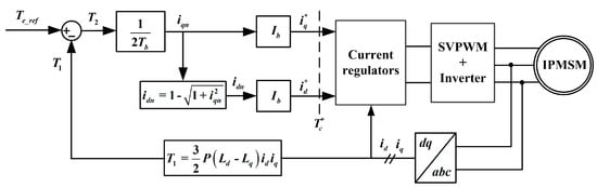
Figure 1.
The torque control strategy structure with maximum-torque-per-ampere (MTPA) conditions.
The reference torque is given by an outer controller, and only positive reference torque will be taken into account in this paper. Considering the machine reluctance torque as the torque feedback, comparing with the torque reference , then the excitation torque reference can be obtained. Since the excitation torque is proportional to the q-axis current, the q-axis current reference can be fed by the excitation torque reference through a proportional regulator.
For the sake of simplicity, the per unit model is used in this strategy. Combing (2) and (4), is equal to . Once is given, the per unit value in MTPA condition can be solved as follows.
By combining (6), Equation (8) can be simplified to:
Solving gives:
Since and have been solved, the currents reference vector (, ) can be derived easily. Within the effects of torque control, (, ) will converge asymptotically to the MTPA operating point (, ).
The dynamic analysis findings are as follows: if the q-axis current reference > , then the d-axis current reference < , the machine reluctance torque increases, then excitation torque reference will decrease, and will decrease consequently; in the case of < , it is exactly the same way. This torque controller keeps adjusting until it is equal to and then is equal to , i.e., (, ) is the equilibrium point of (, ). The relationship between the given torque and MTPA operating point is shown in Figure 2.
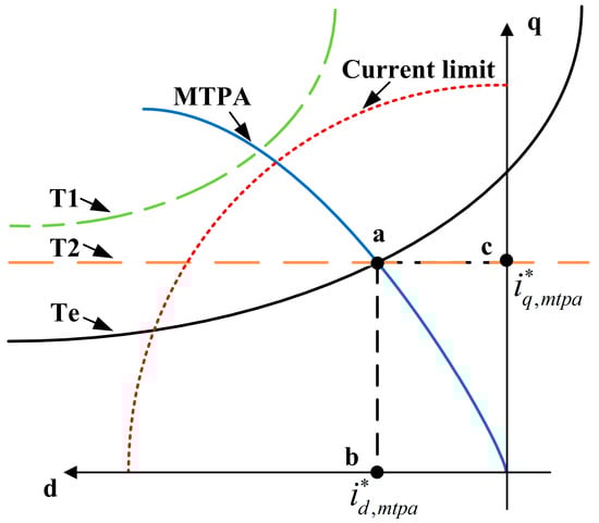
Figure 2.
The relationship between the given torque and MTPA operating point.
The reference currents can be used properly in the field-oriented control (FOC) scheme to achieve MTPA trajectory tracking.
3.2. Stability Analysis and Convergence Rate Estimation
The dynamic analysis describes roughly the process of tracking MTPA operating points. In this section, the stable performance of torque control strategy will be proven as follows.
Within the proper design of vector control, the d- and q-axis current closed loop systems can be approximated by a low pass filter [], i.e.,:
where, is the time constant of current closed loop. Denoting the torque , and are given by and . Meanwhile, their relationships should correspond to (1) and (2), i.e., , , and .
Making the time derivative of and combining the result with (11), the following equation can be obtained:
Differentiating (12) with respect to time again and then inserting the result into (12), it follows that:
As expressed in Figure 1, equals to , and equals to . Thus, , , and . Inserting the results into (13), it holds that:
According to the singular perturbation approximation principle [], the second order term can be neglected because is far less than . Combing with , the derivative of is given by:
Based on (10), the derivative of can be expressed as:
Apparently, when and , i.e., when (, ) converge to the MTPA operating point. Considering the Lyapunov function , the derivative of is given by (17):
Since only positive reference torque is taken into account, > 0 and < 0. Besides, . Therefore, and , i.e., this system is asymptotically stable.
According to (17), , solving gives:
where, is the initial time, is the initial value of . This shows that the convergence rate of is higher than .
According to (11), solving (, ) gives:
where (, ) are the initial values of (, ). Equation (19) shows the convergence rate of (, ) equals . Obviously, the convergence rate of is higher than (, ). That means the convergence rate of the torque loop is higher than the current loop, i.e., coverages to and (, ) converge to (, ) before (, ) converge to (, ). Therefore, this torque control strategy is suitable for dynamic MTPA trajectory tracking.
4. Results
4.1. Simulation Results
To validate the proposed torque control strategy, the whole system was simulated in Matlab/Simulink. The parameters of interior permanent magnet synchronous machine (IPMSM) are tabulated in Table 1.

Table 1.
Parameters of IPMSM.
The rated speed was set to 1000 rpm. The machine speed was controlled by an outer speed controller, which provided the reference torque . In order to maintain a constant speed, was varied with the load torque . Based on the different state of , the simulation was divided into three stages. Stage 1: 0 s~0.2 s, increased from 0 Nm to 50 Nm equably. Stage 2: 0.2 s~0.4 s, maintained at 50 Nm. Stage 3: 0.4 s~1 s, dropped to 40 Nm at 0.4 s, then remained constant until 1 s. Figure 3 shows the torque and current response of MTPA trajectory tracking under the torque control strategy. Figure 3a shows the drop to 40 Nm at 0.4 s, then remaining constant until 1 s. Figure 3 shows the torque and current response of MTPA trajectory tracking under the torque control strategy. Figure 3a shows the response of the machine speed. Figure 3b shows the response of reference torque and machine torque . Figure 3c shows the response of the d-axis reference current and stator current . Figure 3d shows the response of the q-axis reference current and stator current . It can be seen that followed closely in these load conditions, even if changed continuously. Besides, and varied with .
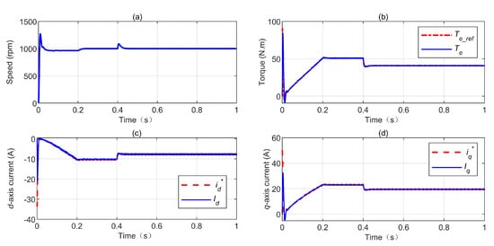
Figure 3.
The simulation results: (a) machine speed; (b) reference and machine torque; (c) d-axis reference current and stator current; (d) q-axis reference current and stator current.
Figure 4 reports the transient current locus and the desired MTPA trajectory. It can be seen that (, ) converged to the MTPA operating point asymptotically. The simulation results reveal that this online MTPA trajectory tracking strategy is excellent in steady and transient conditions.
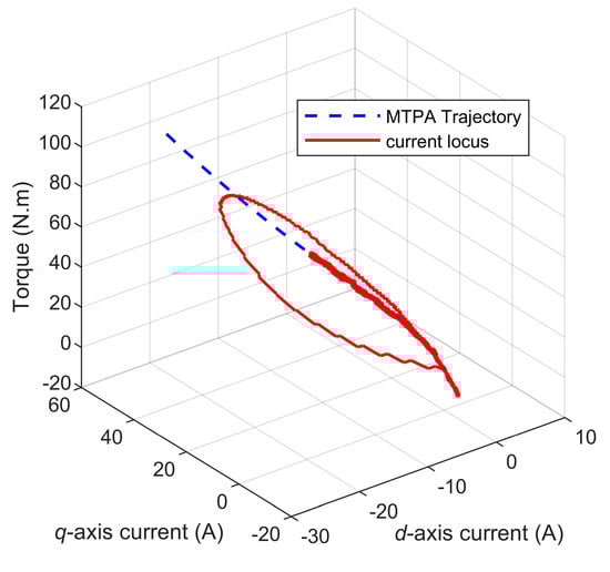
Figure 4.
The transient current locus and the desired MTPA trajectory.
4.2. Experimental Results
The proposed control approach was validated through experimental investigations, which were conducted on a laboratory IPMSM drive system, shown in Figure 5.
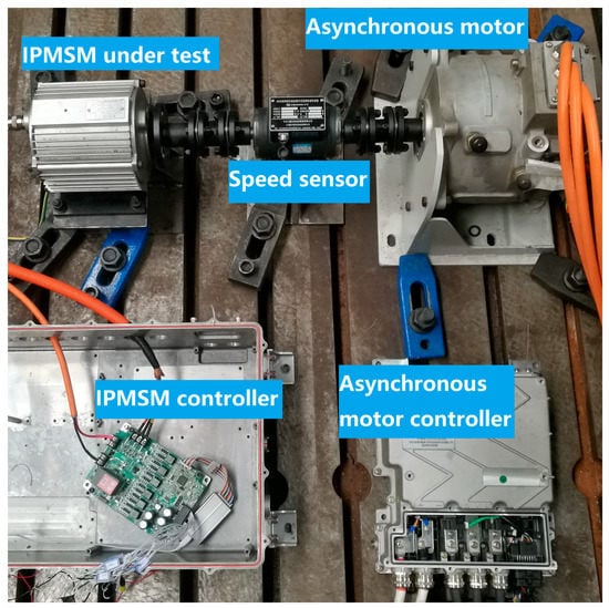
Figure 5.
Experimental setup.
The experiment platform contained a 3 kW IPMSM, which was used for applying the proposed strategy and an asynchronous motor operated as a programmable load, which was controlled by the PC. The tested motor was driven by the three-phase voltage source PWM (Pulse Width Modulation) inverter and the controller was implemented in the TMS320F28335 DSP (Digital Signal Processor). The position of the tested motor was estimated by a sliding-mode observer. The machine reluctance torque was calculated based on the machine parameters. The parameters of the IPMSM were tabulated in Table 1.
The rated speed was set to 1000 rpm. The machine speed response is shown in Figure 6a. The response of the reference torque is shown in Figure 6b. The response of the d-axis reference current and stator current are shown in Figure 6c. The response of the q-axis reference current and stator current are shown in Figure 6d. Figure 7 shows the transient response of the reference torque and q-axis reference current. It can be seen that the stator current can follow the current reference closely. The torque reference was adjusted with speed and the current reference was adjusted with torque reference. The experiment results reveal that this strategy is active.
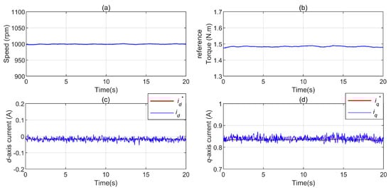
Figure 6.
The experiment result: (a) machine speed; (b) reference torque; (c) d-axis reference current and d-axis stator current; (d) q-axis reference current and q-axis stator current.
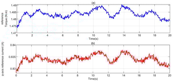
Figure 7.
The experiment result: (a) reference torque; (b) q-axis reference current.
5. Conclusions
A novel torque controller was presented in this paper. Combined with the MTPA condition, this torque control strategy can track the MTPA trajectory online. The reference torque consisted of two parts, excitation torque and reluctance torque. The excitation torque was fed to the proportional regulator, which produced the q-axis current reference. Once the q-axis current reference was given, the d-axis current reference could be calculated online based on the MTPA condition in the per unit model. Moreover, the implementation of the per unit model can simplify the MTPA condition, reduce the calculation burden, and make the machine parameters independent. In addition, parameter estimation algorithms can be conveniently combined with the torque controller to improve accuracy. This strategy combined the MTPA condition with the torque controller to realize MTPA trajectory tracking online. Moreover, the stability and dynamic performance were proven analytically. The simulation and experiment results show the excellent performance of the strategy in steady and transient conditions.
Author Contributions
Data curation, X.J.; Formal analysis, J.S.; Investigation, J.S.; Methodology, J.S.; Project administration, C.L.; Software, J.X.; Supervision, C.L.
Funding
This work was supported by Ministry of Science and Technology of the People’s Republic of China under Grant 2017YFB0103801.
Conflicts of Interest
The authors declare no conflict of interest.
References
- Lin, F.J.; Hung, Y.C.; Chen, J.M.; Yeh, C.M. Sensorless IPMSM Drive System Using Saliency Back-EMF-Based Intelligent Torque Observer With MTPA Control. IEEE Trans. Ind. Inform. 2014, 10, 1226–1241. [Google Scholar]
- Lu, X.M.; Iyer, K.L.V.; Mukherjee, K.; Ramkumar, K.; Kar, N.C. Investigation of Permanent-Magnet Motor Drives Incorporating Damper Bars for Electrified Vehicles. IEEE. Trans. Ind. Electron. 2015, 62, 3234–3244. [Google Scholar] [CrossRef]
- Yang, Z.; Shang, F.; Brown, I.P.; Krishnamurthy, M. Comparative Study of Interior Permanent Magnet, Induction, and Switched Reluctance Motor Drives for EV and HEV Applications. IEEE Trans. Transp. Electron. 2015, 1, 245–254. [Google Scholar] [CrossRef]
- Ni, R.G.; Xu, D.G.; Wang, G.L.; Ding, L.; Zhang, G.Q.; Qu, L.Z. Maximum Efficiency Per Ampere Control of Permanent-Magnet Synchronous Machines. IEEE Trans. Ind. Electron. 2015, 62, 2135–2143. [Google Scholar] [CrossRef]
- Ge, H.; Miao, Y.; Bilgin, B.; Nahid-Mobarakeh, B.; Emadi, A. Speed Range Extended Maximum Torque Per Ampere Control for PM Drives Considering Inverter and Motor Nonlinearities. IEEE T. Power Electron. 2017, 32, 7151–7159. [Google Scholar] [CrossRef]
- Jahns, T.M.; Kliman, G.B.; Neumann, T.W. Interior Permanent-Magnet Synchronous Motors for Adjustable-Speed Drives. IEEE Trans. Ind. Appl. 1986, 22, 738–747. [Google Scholar] [CrossRef]
- Jung, S.-Y.; Hong, J.; Nam, K. Current Minimizing Torque Control of the IPMSM Using Ferrari’s Method. IEEE Trans. Power Electron. 2013, 28, 5603–5617. [Google Scholar] [CrossRef]
- Nalepa, R.; Orlowska-Kowalska, T. Optimum Trajectory Control of the Current Vector of a Nonsalient-Pole PMSM in the Field-Weakening Region. IEEE Trans. Ind. Electron. 2012, 59, 2867–2876. [Google Scholar] [CrossRef]
- Dianov, A.; Kim, Y.-K.; Lee, S.-J.; Lee, S.-T. Robust Self-Tuning MTPA Algorithm for IPMSM Drives. In Proceedings of the 34th Annual Conference of IEEE Industrial Electronics 2008, Orlando, FL, USA, 10–13 November 2008. [Google Scholar]
- Morimoto, S.; Sanada, M.; Takeda, Y. Wide-speed operation of interior permanent magnet synchronous motors with high-performance current regulator. IEEE Trans. Ind. Appl. 1994, 30, 920–926. [Google Scholar] [CrossRef]
- Ahmed, A.; Sozer, Y.; Hamdan, M. Maximum Torque per Ampere Control for Buried Magnet PMSM Based on DC-Link Power Measurement. IEEE Trans. Power Electron. 2017, 32, 1311. [Google Scholar] [CrossRef]
- Lin, F.J.; Liu, Y.T.; Yu, W.A. Power Perturbation Based MTPA With an Online Tuning Speed Controller for an IPMSM Drive System. IEEE Trans. Ind. Electron. 2018, 65, 3677–3687. [Google Scholar] [CrossRef]
- Liu, G.H.; Wang, J.; Zhao, W.X.; Chen, Q. A Novel MTPA Control Strategy for IPMSM Drives by Space Vector Signal Injection. IEEE Trans. Ind. Electron. 2017, 64, 9243–9252. [Google Scholar] [CrossRef]
- Antonello, R.; Carraro, M.; Zigliotto, M. Maximum-Torque-Per-Ampere Operation of Anisotropic Synchronous Permanent-Magnet Motors Based on Extremum Seeking Control. IEEE Trans. Ind. Electron. 2014, 61, 5086–5093. [Google Scholar] [CrossRef]
- Lin, F.J.; Chen, S.G.; Liu, Y.T.; Chen, S.Y. A power perturbation-based MTPA control with disturbance torque observer for IPMSM drive system. Trans. Inst. Meas. Control 2018, 40, 3179–3188. [Google Scholar] [CrossRef]
- Mohamed, A.R.I.; Lee, T.K. Adaptive self-tuning MTPA vector controller for IPMSM drive system. IEEE Trans. Energy Convers. 2006, 21, 636–644. [Google Scholar] [CrossRef]
- Morimoto, S.; Ueno, T.; Sanada, M.; Yamagiwa, A.; Takeda, Y.; Hirasa, T. Effects and Compensation of Magnetic Saturation in Permanent Magnet Synchronous Motor Drives. In Proceedings of the 1993 IEEE Industry Applications Conference Twenty-Eighth IAS Annual Meeting, Toronto, ON, Canada, 2–8 October 1993. [Google Scholar]
- Consoli, A.; Scarcella, G.; Scelba, G.; Testa, A. Steady-State and Transient Operation of IPMSMs Under Maximum-Torque-per-Ampere Control. IEEE Trans. Ind. Appl. 2010, 46, 121–129. [Google Scholar] [CrossRef]
- Underwood, S.J.; Husain, I. Online Parameter Estimation and Adaptive Control of Permanent-Magnet Synchronous Machines. IEEE Trans. Ind. Electron. 2010, 57, 2435–2443. [Google Scholar] [CrossRef]
- Liu, Q.; Hameyer, K. High-Performance Adaptive Torque Control for an IPMSM With Real-Time MTPA Operation. IEEE Trans. Energy Convers. 2017, 32, 571–581. [Google Scholar] [CrossRef]
© 2019 by the authors. Licensee MDPI, Basel, Switzerland. This article is an open access article distributed under the terms and conditions of the Creative Commons Attribution (CC BY) license (http://creativecommons.org/licenses/by/4.0/).