Large Scale Renewable Energy Integration: Issues and Solutions

 , ,
, ,  and
and
Abstract
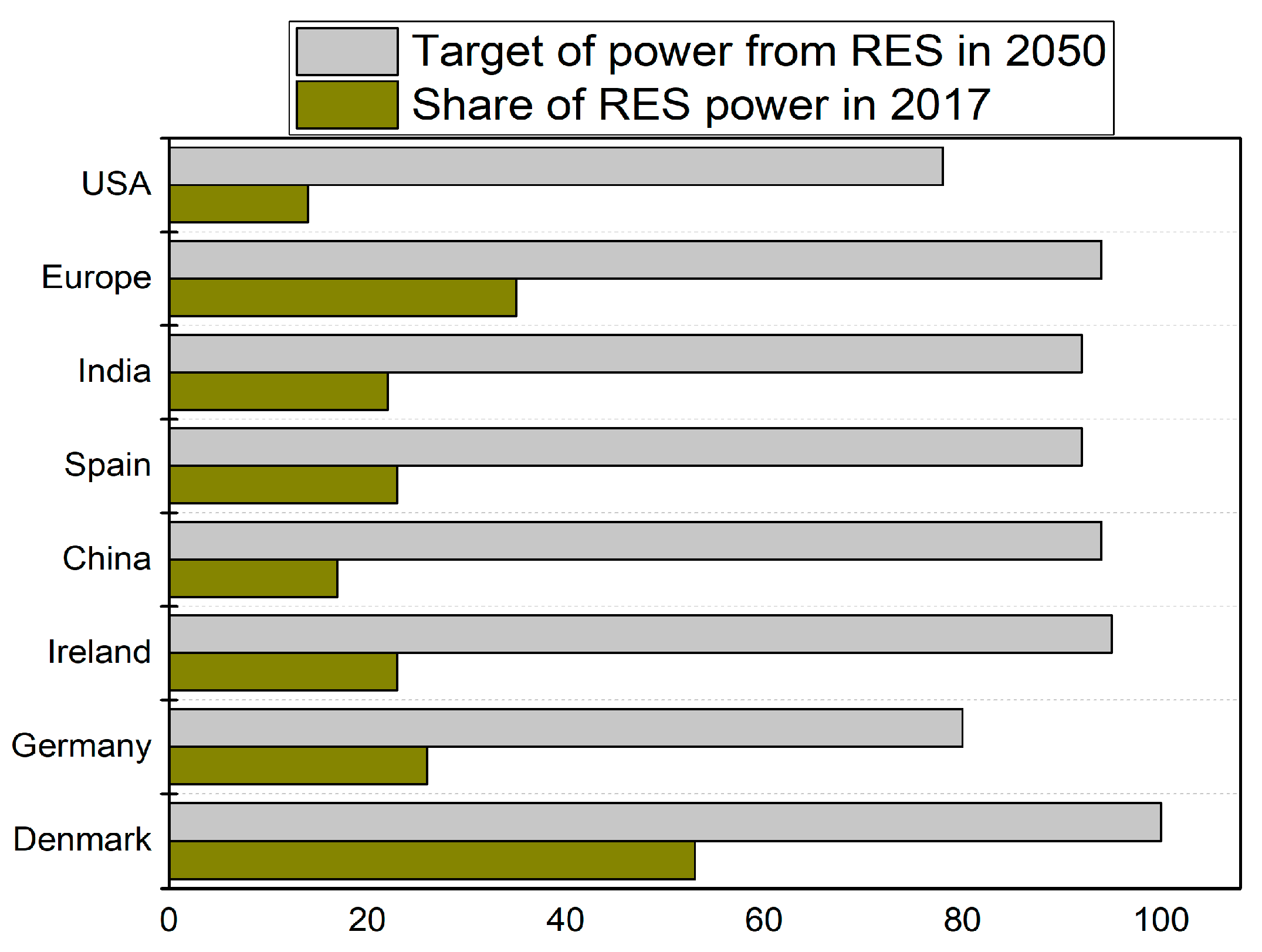
1. Introduction
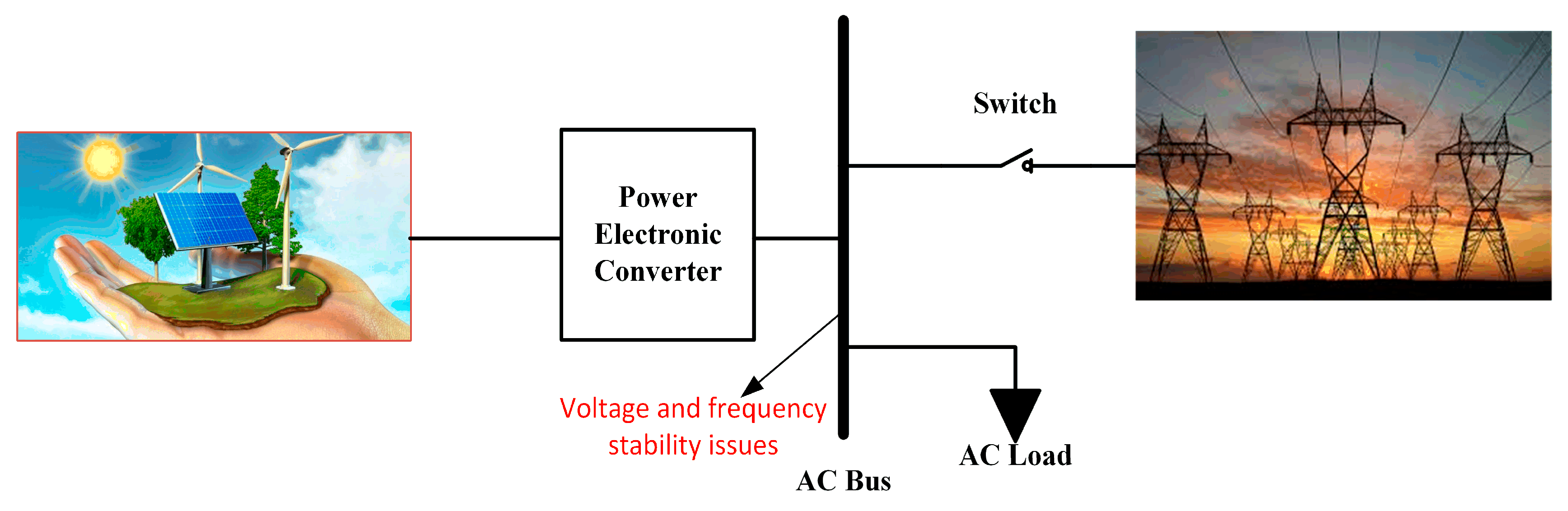
2. Grid Integration Issues with a High Share of RES
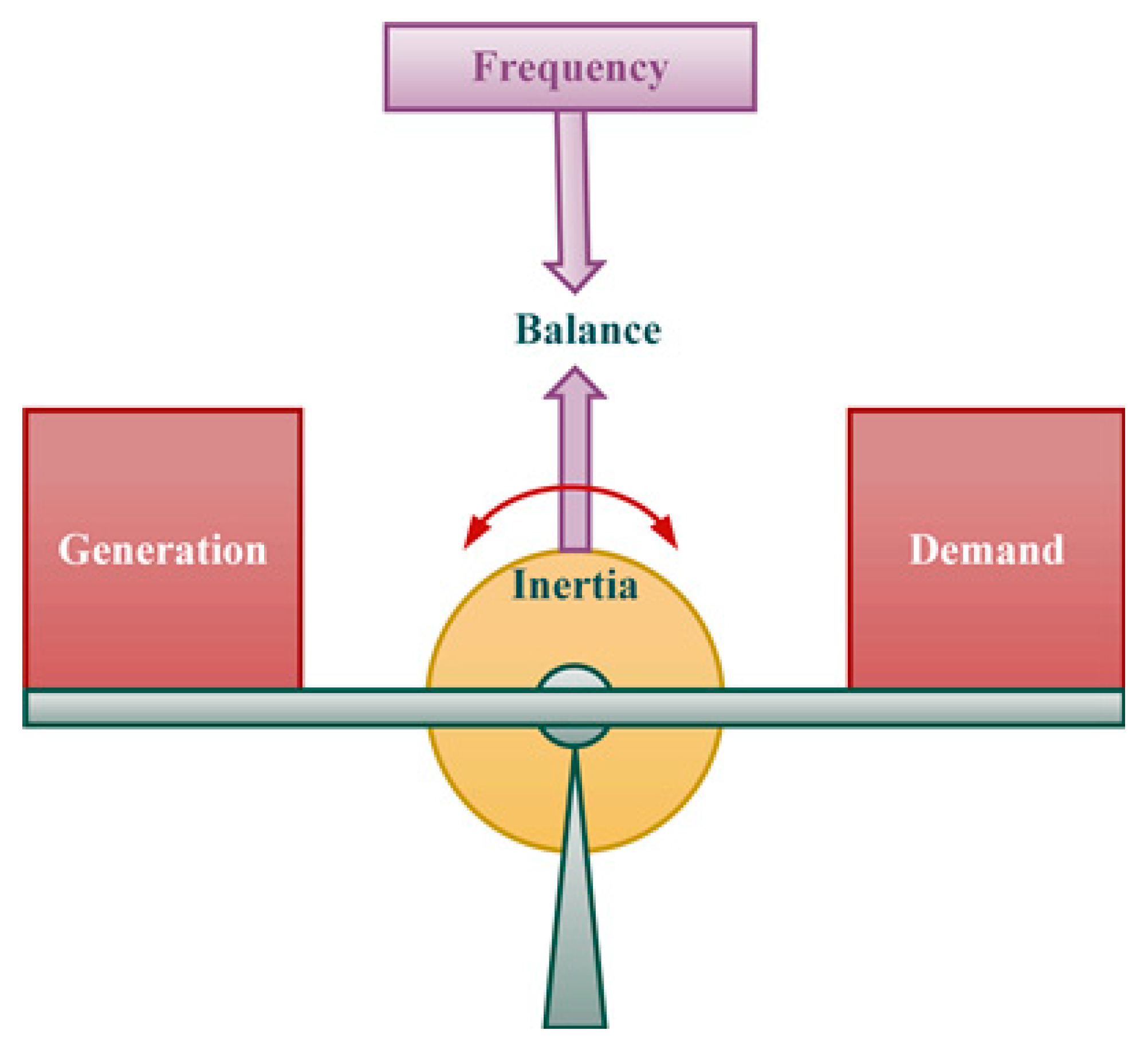
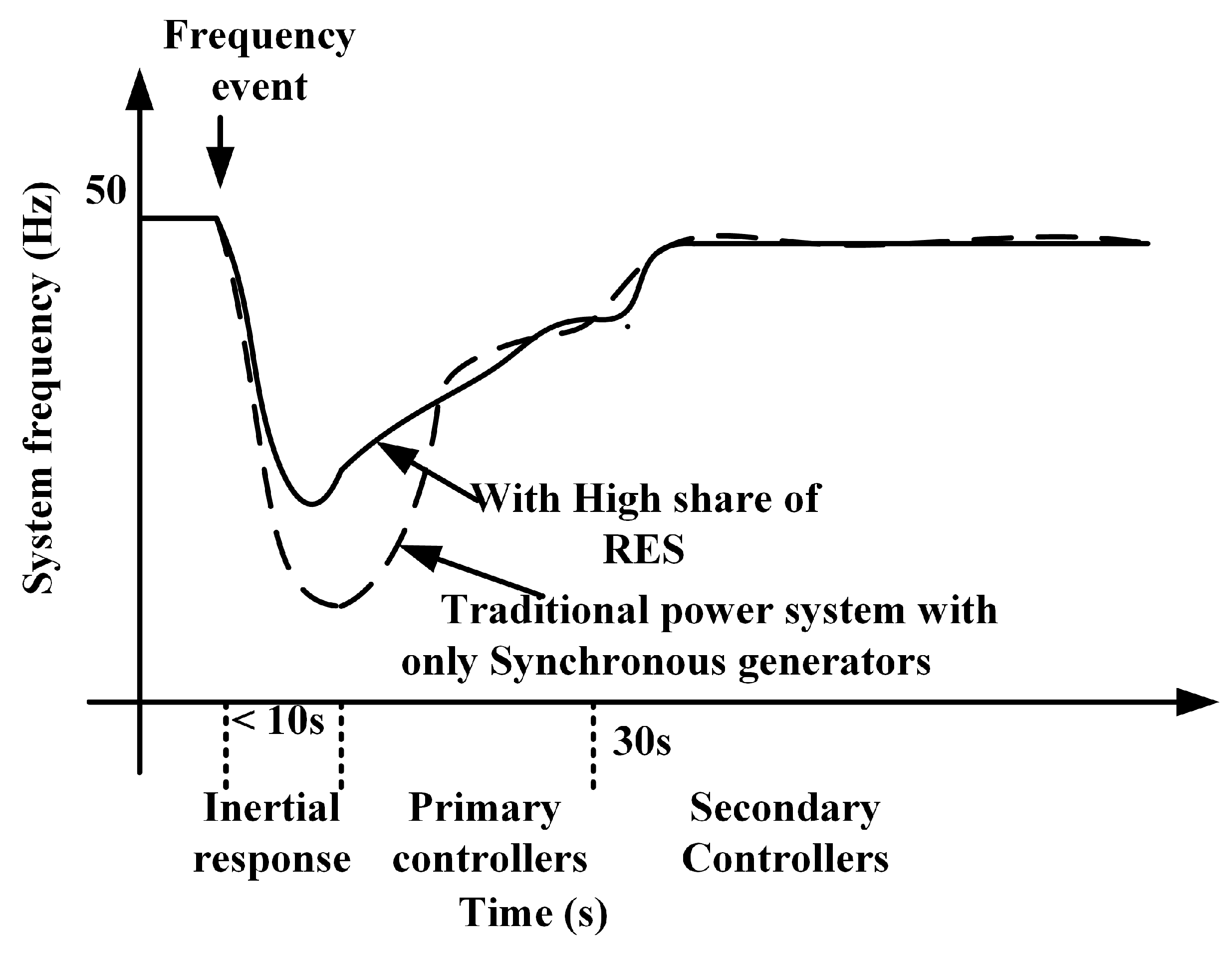
2.1. Impact of Large-Scale Integration of RES on Frequency
- Inertial response (a few seconds).
- Primary frequency response—Governor Response (1–10 s).
- Secondary frequency response—Area Governor Control response (seconds to minutes).
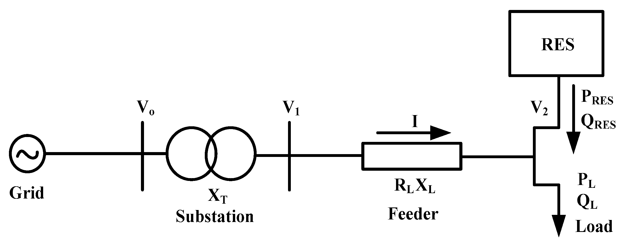
2.2. Voltage Rise and Fluctuation
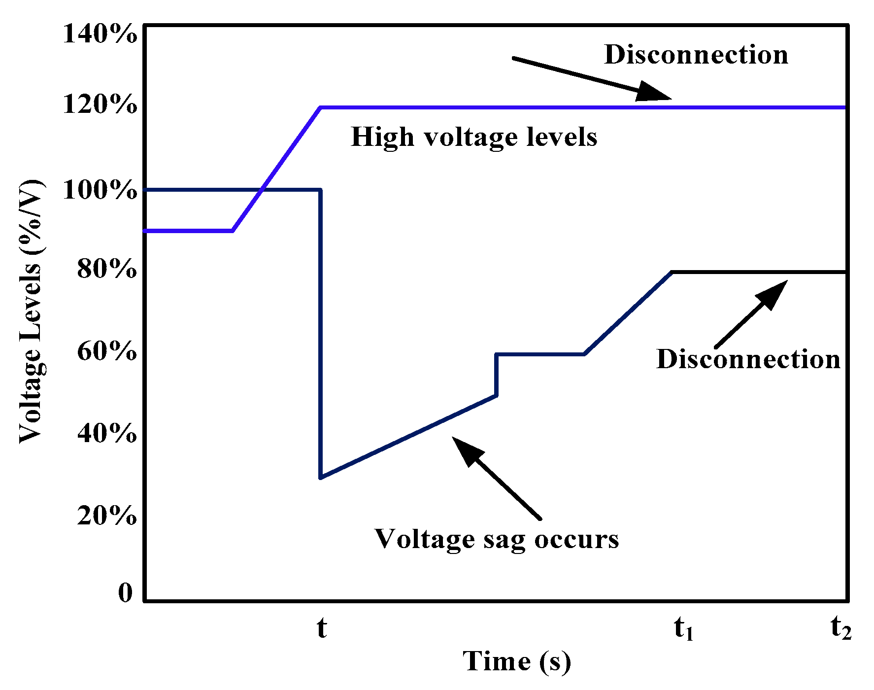
Impact of RES on Voltage Drops in the Grid
3. Solutions for Variable RES
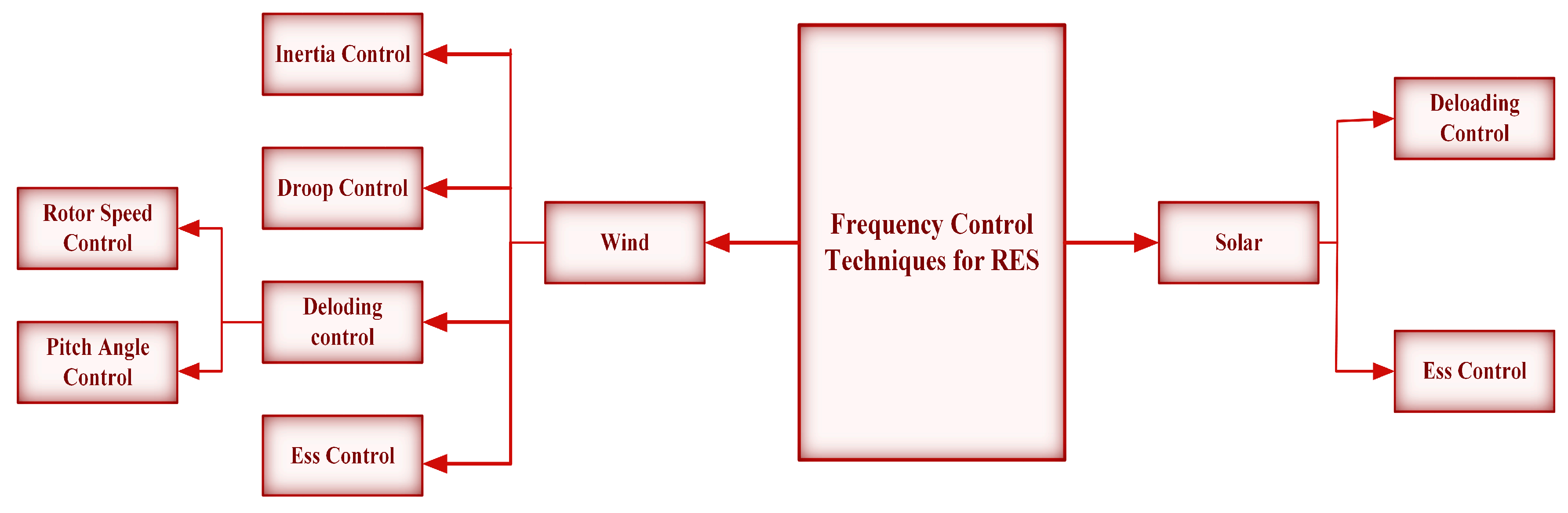
3.1. Frequency Control Techniques for RES
3.1.1. Control techniques Used for Wind Turbines
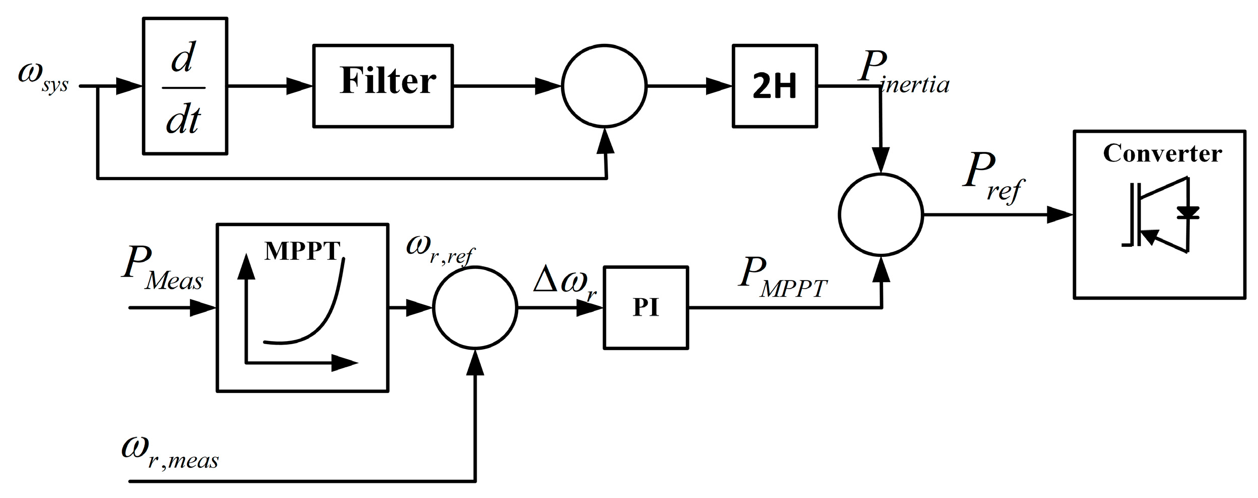
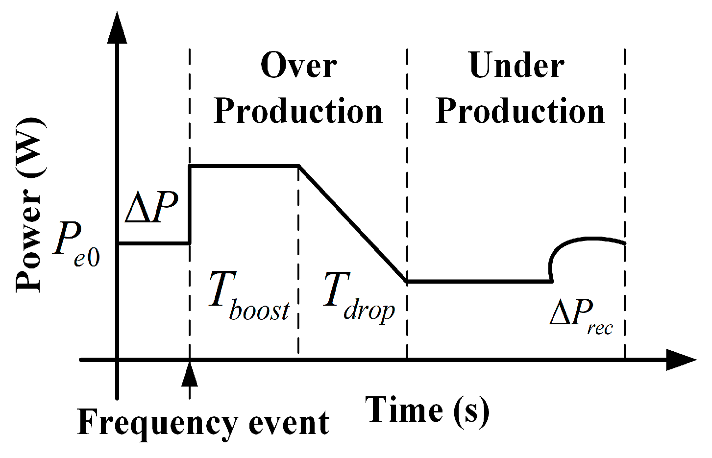
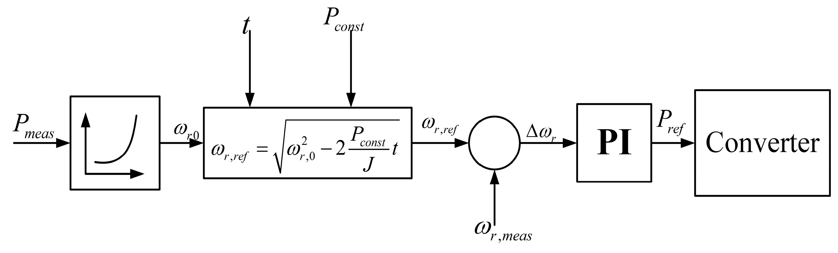
3.1.2. Inertia Control
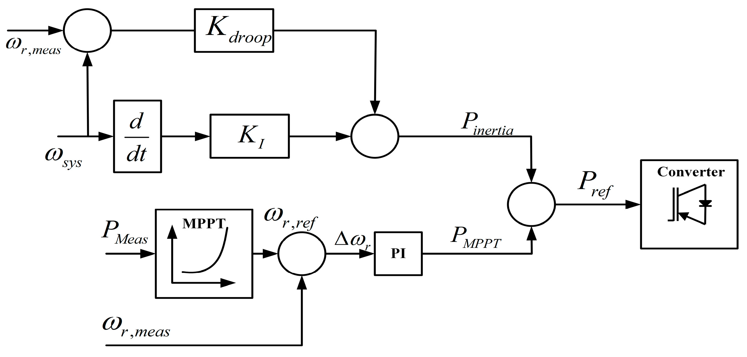
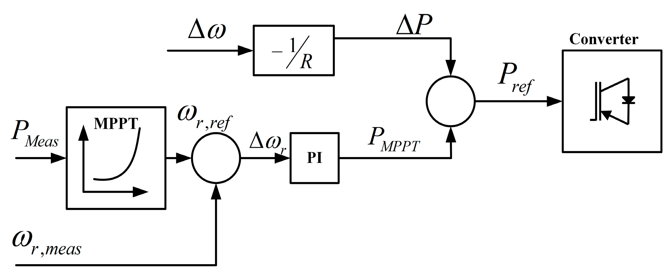
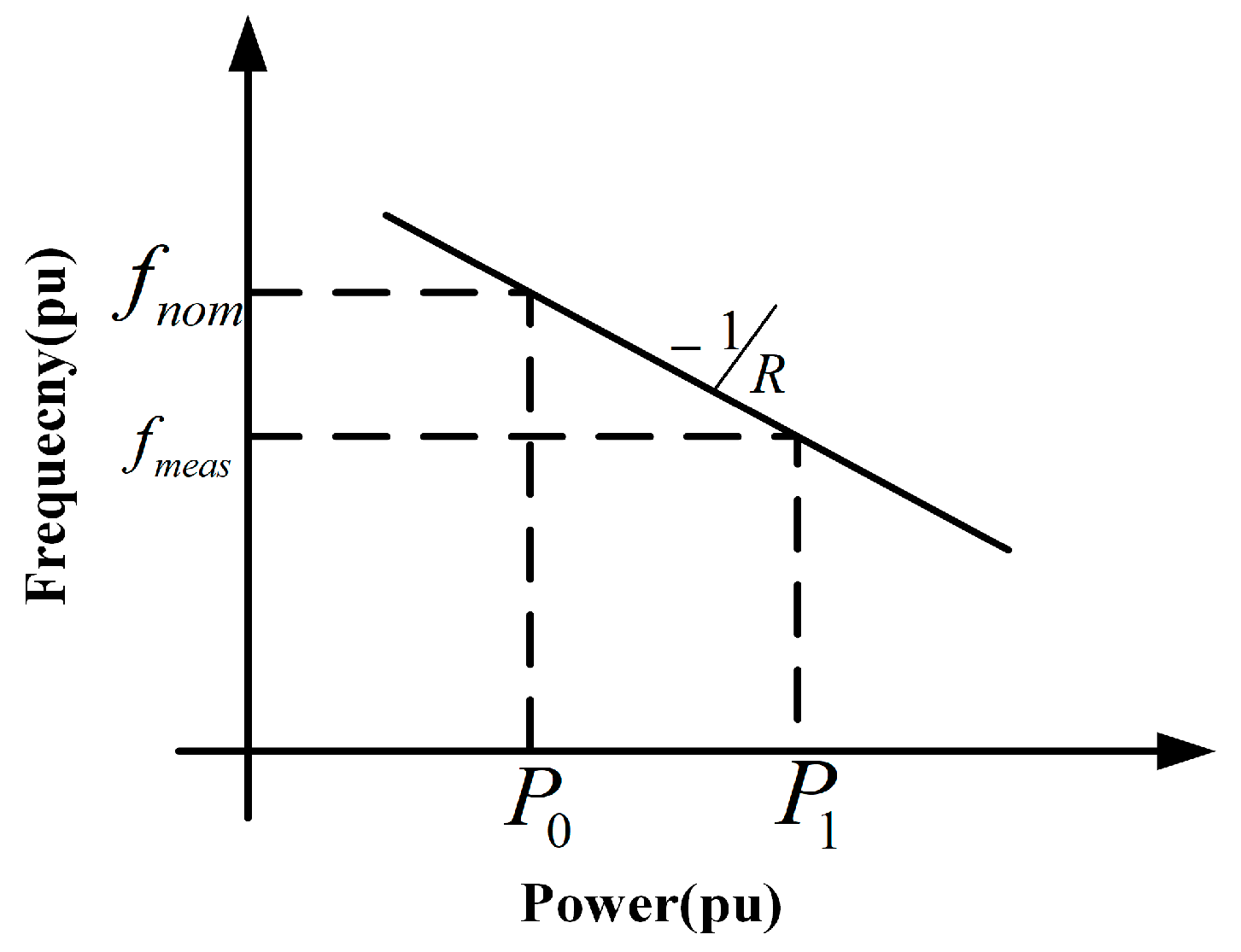
3.1.3. Droop Control for Frequency Regulation
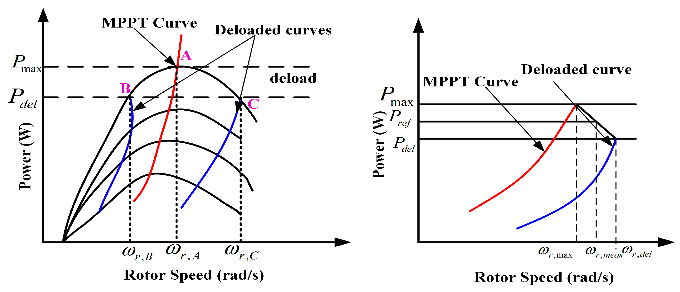
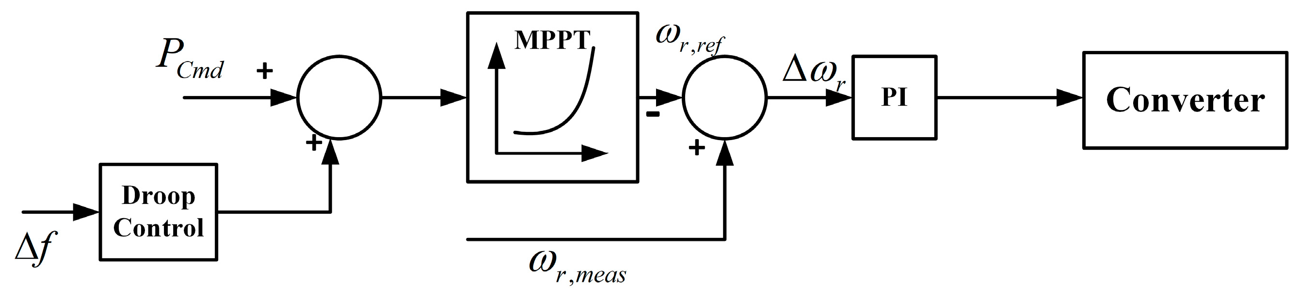
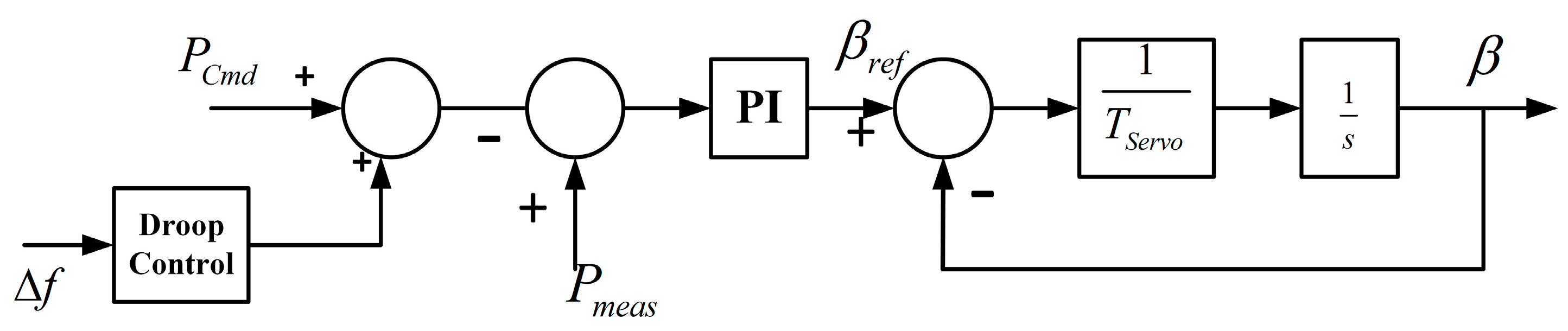
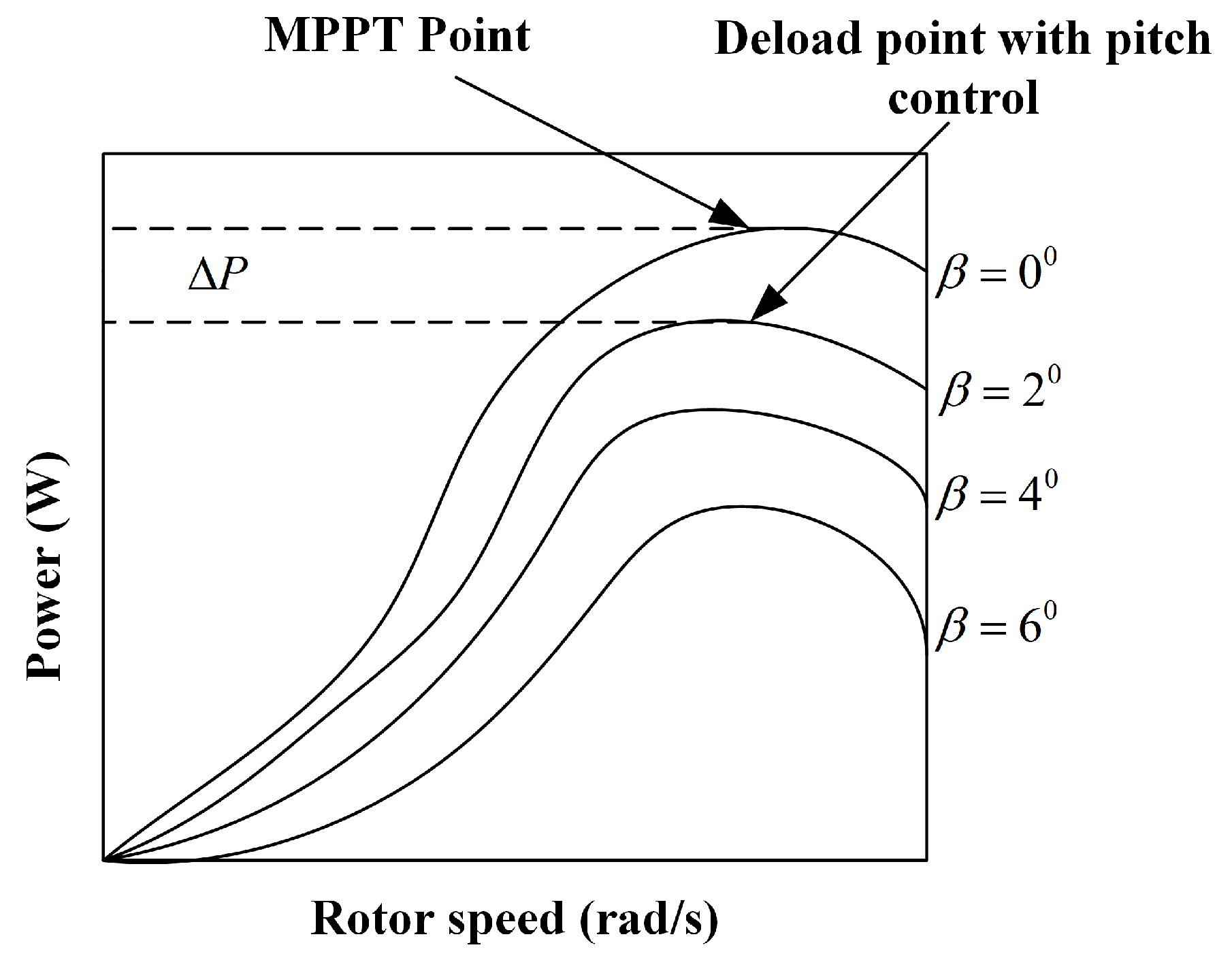
3.1.4. De-Loaded Operation in Wind Turbines
3.1.5. Solar Photovoltaic Array in Frequency Regulation
- De-loaded operation of PV.
- Use of ESS.
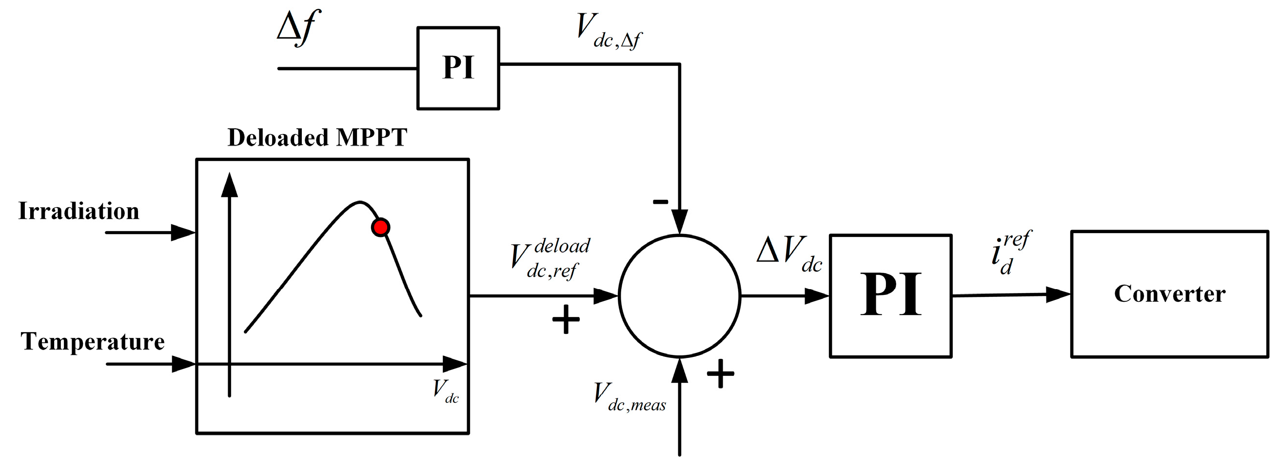
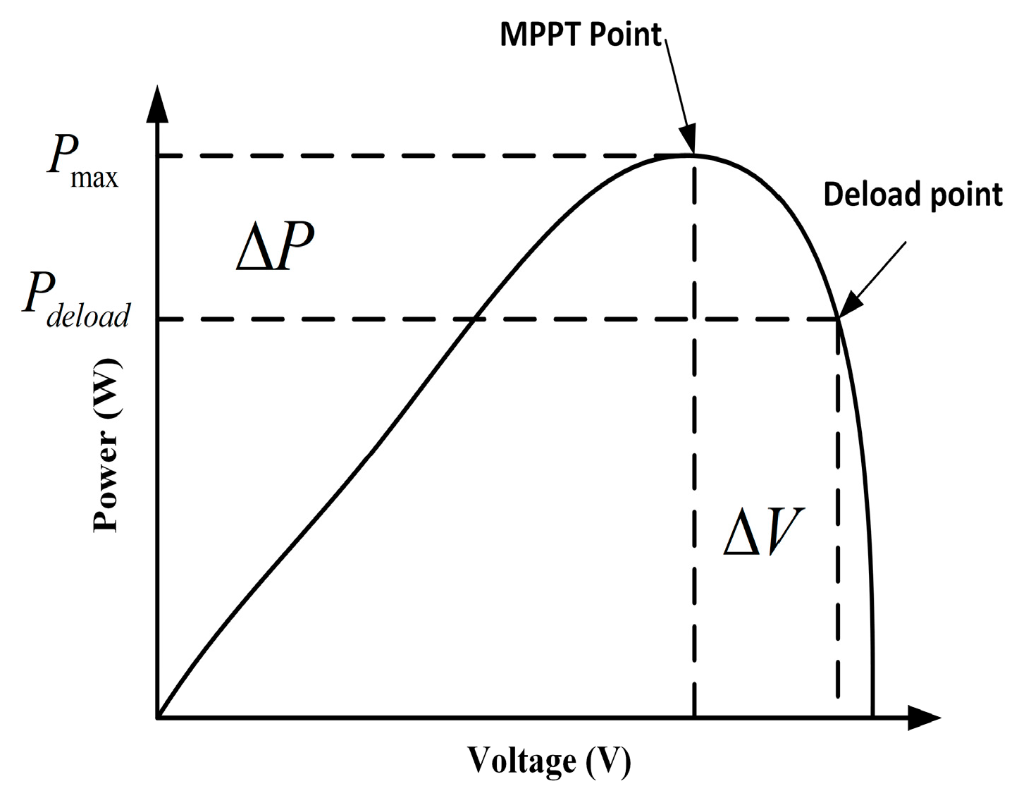
3.1.6. De-Loaded Operation of a PV Generator [32]
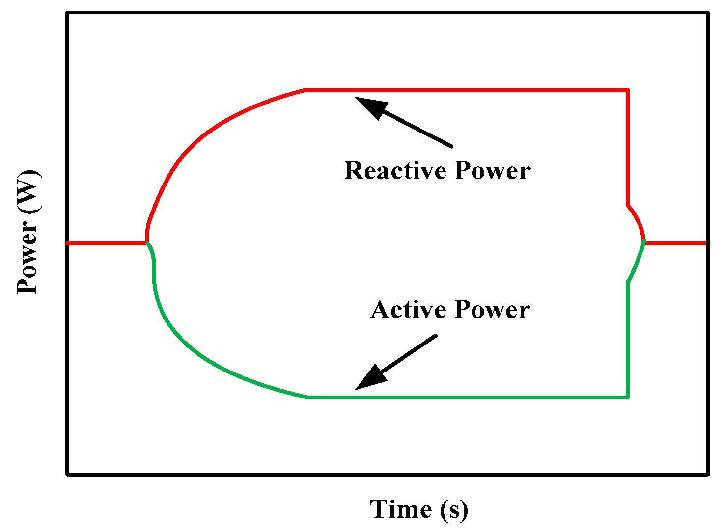
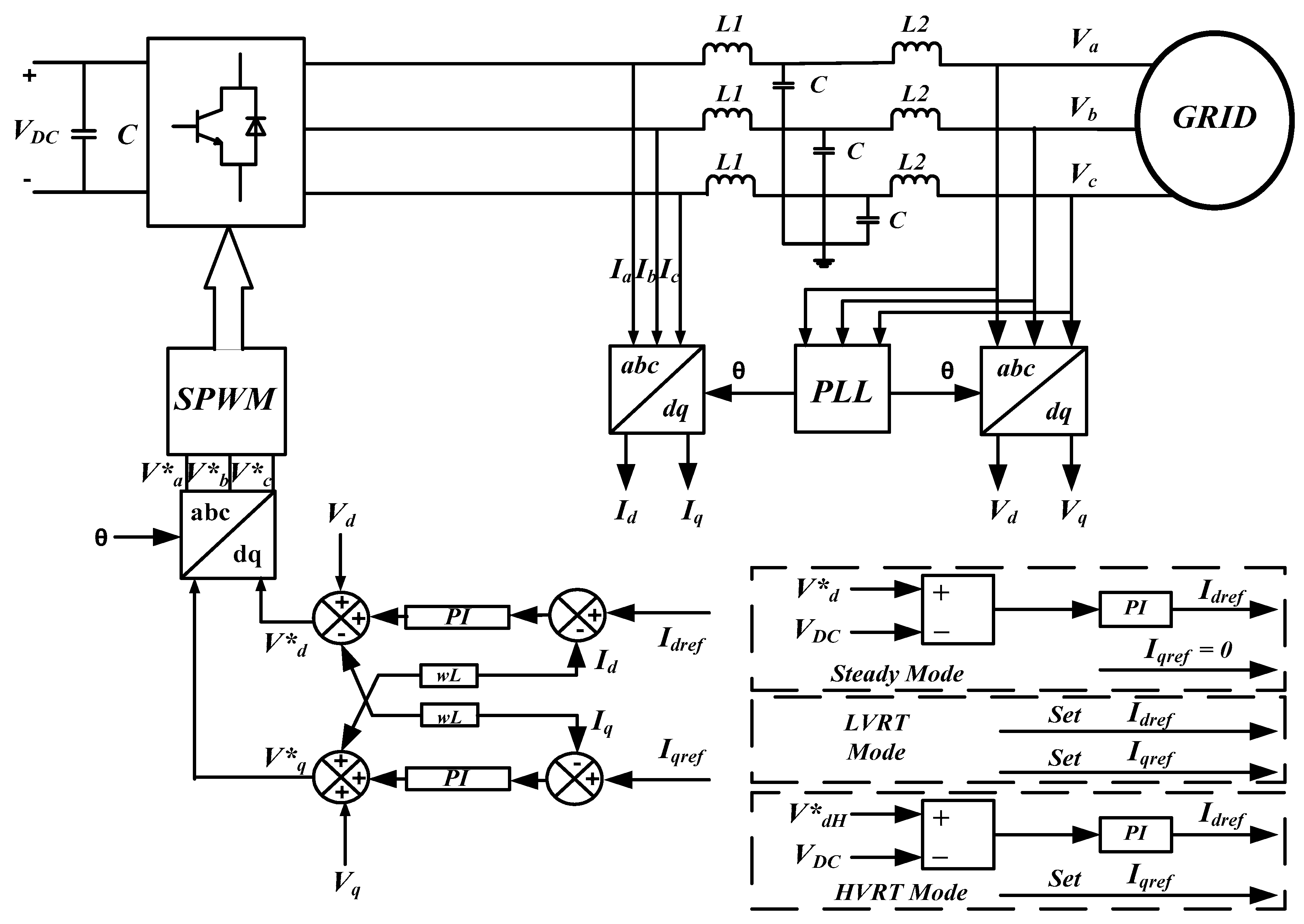
3.2. Voltage Control Techniques
- (1)
- Regulating the voltage,
- (2)
- Improving the stability of the system,
- (3)
- Minimizing power losses,
- (4)
- Effective utilization of machines associated with the system.
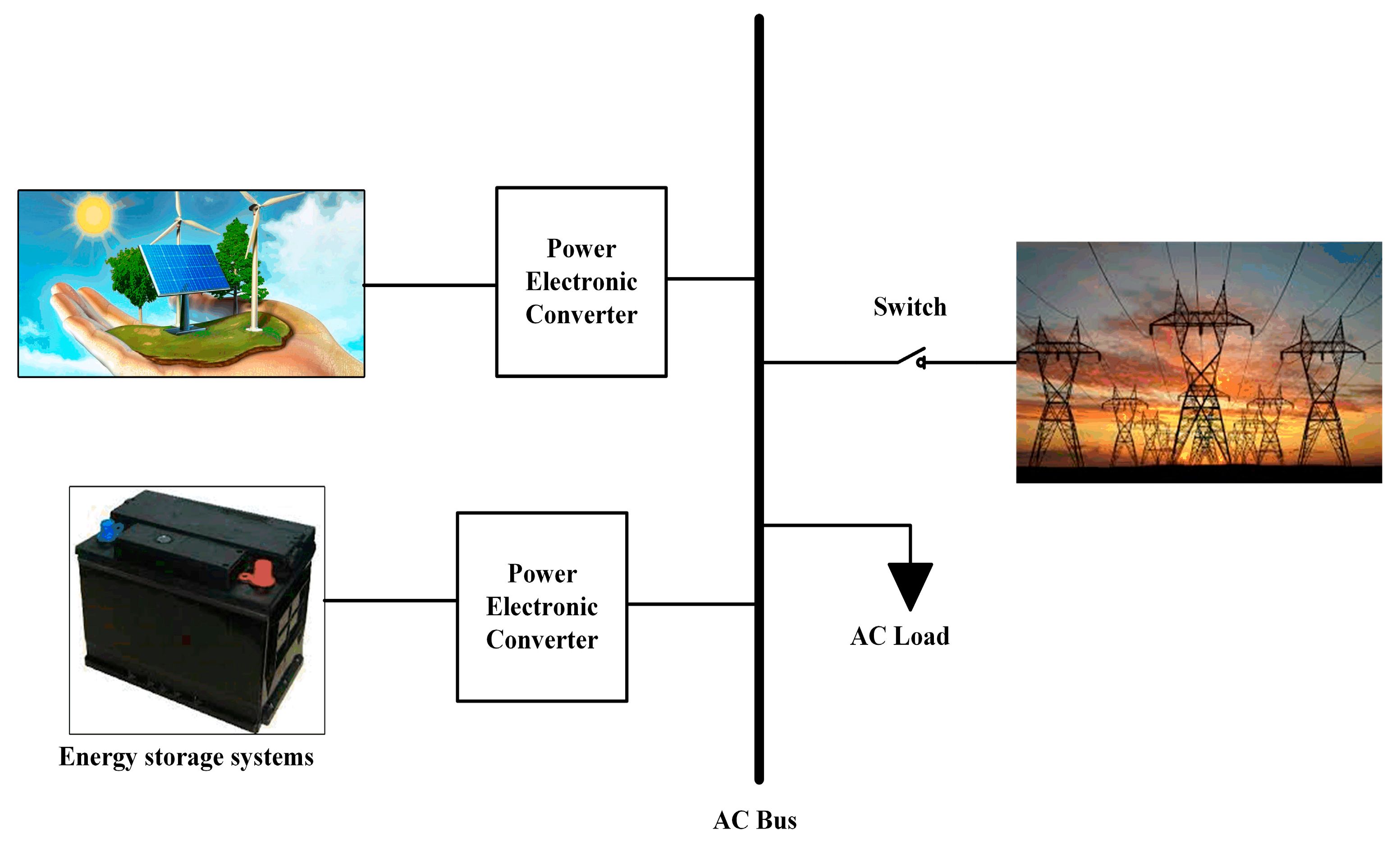
4. ESS Support
5. Smart Grid Features in Voltage Control with RES
6. Conclusions
Author Contributions
Funding
Acknowledgments
Conflicts of Interest
References
- Ulbig, A.; Borsche, T.S.; Andersson, G. Impact of low rotational inertia on power system stability and operation. IFAC Proc. 2014, 19, 7290–7297. [Google Scholar] [CrossRef]
- Patel, M.R. Wind and Solar Power Systems: Design, Analysis, and Operation; CRC Press: Boca Raton, FL, USA, 2005; pp. 87–101. [Google Scholar]
- Zhong, Q.C. Virtual Synchronous Machines: A unified interface for grid integration. IEEE Power Electron. Mag. 2016, 3, 18–27. [Google Scholar] [CrossRef]
- Hales, D. Renewables 2018 Global Status Report, Renewable Energy Policy Network. 2018. Available online: http://www.ren21.net/status-of-renewables/global-status-report/ (accessed on 20 April 2019).
- Shah, R.; Mithulananthan, N.; Bansal, R.C.; Ramachandaramurthy, V.K. A review of key power system stability challenges for large-scale PV integration. Renew. Sustain. Energy Rev. 2015, 41, 1423–1436. [Google Scholar] [CrossRef]
- Eriksen, P.B.; Ackermann, T.; Smith, P.; Winter, W.; Garcia, J.M. System operation with high wind penetration. IEEE Power Energy Mag. 2005, 3, 65–74. [Google Scholar] [CrossRef]
- Huang, Z.M. Research of the problems of renewable energy orderly combined to the grid in smart grid. In Proceedings of the Asia-Pacific Power and Energy Engineering Conference (APPEEC), Chengdu, China, 28–31 March 2010. [Google Scholar]
- Lee, C.-T.; Hsu, C.-W.; Cheng, P.-T. A Low-Voltage Ride- Through Technique for Grid-Connected Converters of Distributed Energy Resources. IEEE Trans. Ind. Appl. 2011, 47, 1821–1832. [Google Scholar] [CrossRef]
- Zaman, B.A. 100\% Variable Renewable Energy Grid: Survey of Possibilities. Master’s Thesis, University of Michigan, Ann Arbor, MI, USA, 2018. [Google Scholar]
- Tamrakar, U.; Shrestha, D.; Maharjan, M.; Bhattarai, B.; Hansen, T.; Tonkoski, R. Virtual Inertia: Current Trends and Future Directions. Appl. Sci. 2017, 7, 654. [Google Scholar] [CrossRef]
- Cochran, J.; Denholm, P.; Speer, B.; Miller, M.; Cochran, J.; Denholm, P.; Speer, B.; Miller, M. Grid Integration and the Carrying Capacity of the US Grid to Incorporate Variable Renewable Energy; National Renewable Energy Laboratory: Golden, CO, USA, 2015. [Google Scholar]
- Carvalho, P.M.S.; Correia, P.F.; Ferreira, L. Distributed reactive power generation control for voltage rise mitigation in distribution networks. IEEE Trans. Power Syst. 2008, 23, 766–772. [Google Scholar] [CrossRef]
- El-Tamaly, H.H.; Wahab, M.A.A.; Kasem, A.H. Simulation of directly grid-connected wind turbines for voltage fluctuation evaluation. Int. J. Appl. Eng. Res. 2007, 2, 15–39. [Google Scholar]
- Katiraei, F.; Agüero, J.R. Solar PV integration challenges. IEEE Power Energy Mag. 2011, 9, 62–71. [Google Scholar] [CrossRef]
- Viawan, F.A.; Sannino, A.; Daalder, J. Voltage control with on-load tap changers in medium voltage feeders in presence of distributed generation. Electr. Power Syst. Res. 2007, 77, 1314–1322. [Google Scholar] [CrossRef]
- Knudsen, J.N.N.H. Introduction to the modelling of wind turbines. In Wind Power in Power Systems; Wiley: Chichester, UK, 2005. [Google Scholar]
- Sun, Y.; Member, S.; Zhang, Z.; Li, G.; Lin, J. Review on Frequency Control of Power Systems with Wind Power Penetration. In Proceedings of the International Conference on Power System Technology, Hangzhou, China, 24–28 October 2010; pp. 1–8. [Google Scholar] [CrossRef]
- Nguyen, H.T.; Yang, G.; Nielsen, A.H.; Jensen, P.H. Frequency Stability Enhancement for Low Inertia Systems using Synthetic Inertia of Wind Power. In Proceedings of the 2017 IEEE Power & Energy Society General Meeting, Chicago, IL, USA, 16–20 July 2017. [Google Scholar]
- Keung, P.; Li, P.; Banakar, H.; Ooi, B.T. Kinetic Energy of Wind-Turbine Generators for System Frequency Support. IEEE Trans. Power Syst. 2009, 24, 279–287. [Google Scholar] [CrossRef]
- El Itani, S.; Member, S.; Annakkage, U.D.; Member, S.; Joos, G. Short-Term Frequency Support Utilizing Inertial Response of DFIG Wind Turbines. In Proceedings of the 2011 IEEE Power and Energy Society General Meeting, San Diego, CA, USA, 24–29 July 2011; pp. 1–8. [Google Scholar] [CrossRef]
- Ye, H.; Pei, W.; Qi, Z. Analytical Modeling of Inertial and Droop Responses From a Wind Farm for Short-Term Frequency Regulation in Power Systems. IEEE Trans. Power Syst. 2016, 31, 3414–3423. [Google Scholar] [CrossRef]
- Wu, Y.; Yang, W.; Hu, Y.; Dzung, P.Q. Frequency Regulation at a Wind Farm Using Time-Varying Inertia and Droop Controls. IEEE Trans. Ind. Appl. 2019, 55, 213–224. [Google Scholar] [CrossRef]
- Ekanayake, J.; Holdsworth, L.; Jenkins, N. Control of DFIG wind turbines. Power Eng. 2003, 117, 28–32. [Google Scholar] [CrossRef]
- De Almeida, R.G.; Lopes, J.A.P. Participation of doubly fed induction wind generators in system frequency regulation. Power Syst. IEEE Trans. 2007, 22, 944–950. [Google Scholar] [CrossRef]
- El Mokadem, M.; Courtecuisse, V.; Saudemont, C.; Robyns, B.; Deuse, J. Experimental study of variable speed wind generator contribution to primary frequency control. Renew. Energy 2009, 34, 833–844. [Google Scholar] [CrossRef]
- Pradhan, C.; Bhende, C.N. Enhancement in Primary Frequency Regulation of Wind Generator using Fuzzy-based Control. Electr. Power Components Syst. 2016, 44, 1669–1682. [Google Scholar] [CrossRef]
- El Mokadem, M.; Courtecuisse, V.; Saudemont, C.; Robyns, B. Fuzzy Logic Supervisor-Based Primary Frequency Control Experiments of a Variable-Speed Wind Generator. IEEE Trans. Power Syst. 2009, 24, 407–417. [Google Scholar] [CrossRef]
- Zertek, A.; Member, S.; Verbi, G.; Member, S.; Pantoš, M. A Novel Strategy for Variable-Speed Wind Turbines’ Participation in Primary Frequency Control. IEEE Trans. Sustain. Energy 2012, 3, 791–799. [Google Scholar] [CrossRef]
- Vidyanandan, K.V.; Senroy, N. Primary Frequency Regulation by Deloaded Wind Turbines Using Variable Droop. IEEE Trans. Power Syst. 2013, 28, 837–846. [Google Scholar] [CrossRef]
- Ghosh, S.; Member, S.; Senroy, N. Electromechanical Dynamics of Controlled Variable-Speed Wind Turbines. IEEE Syst. J. 2015, 9, 639–646. [Google Scholar] [CrossRef]
- Moutis, P.; Member, G.S.; Loukarakis, E. Primary Load-Frequency Control from Pitch- Controlled Wind Turbines. In Proceedings of the 2009 IEEE Bucharest PowerTech, Bucharest, Romania, 28 June–2 July 2009; pp. 1–7. [Google Scholar] [CrossRef]
- Rahmann, C.; Castilo, A. Fast frequency response capability of photovoltaic power plants: The necessity of new grid requirements and definitions. Energies 2014, 7, 6306–6322. [Google Scholar] [CrossRef]
- Bae, Y.; Vu, Y.-K.; Kim, R.-Y. Implemental Control Strategy for Grid Stabilization of Grid-Connected PV System Based on German Grid Code in Symmetrical Low-to-Medium Voltage Network. IEEE Trans. Energy Convers. 2013, 28, 619–631. [Google Scholar] [CrossRef]
- Yu, H.; Pan, J.; Xiang, A. A multi-function grid-connected PV system with reactive power compensation for the grid. Solar Energy 2005, 79, 101–106. [Google Scholar] [CrossRef]
- El Moursi, M.S.; Xiao, W.; Kirtley, J.L. Fault ride through capability for grid interfacing large scale PV power plants. IET Gener. Transm. Distrib. 2013, 7, 1027–1036. [Google Scholar] [CrossRef]
- Firouzi, M.; Gharehpetian, G.B. LVRT Performance Enhancement of DFIG-Based Wind Farms by Capacitive Bridge-Type Fault Current Limiter. IEEE Trans. Sustain. Energy 2018, 9, 1118–1125. [Google Scholar] [CrossRef]
- Xie, Z.; Zhang, X.; Zhang, X.; Yang, S.; Wang, L. Improved Ride-Through Control of DFIG during Grid Voltage Swell. IEEE Trans. Ind. Electron. 2015, 62, 3584–3594. [Google Scholar] [CrossRef]
- Fan, S.; Chao, P.; Zhang, F. Modelling and simulation of the photovoltaic power station considering the LVRT and HVRT. J. Eng. 2017, 2017, 1206–1209. [Google Scholar] [CrossRef]
- Li, C.; Wang, R. Building integrated energy storage opportunities in China. Renew. Sustain. Energy Rev. 2012, 16, 6191–6211. [Google Scholar] [CrossRef]
- Basu, A.K.; Chowdhury, S.P.; Chowdhury, S.; Paul, S. Microgrids: Energy management by strategic deployment of DERs—A comprehensive survey. Renew. Sustain. Energy Rev. 2011, 15, 4348–4356. [Google Scholar] [CrossRef]
- Kumar, G.B.; Kumar, G.A.; Eswararao, S.; Gehlot, D. Modelling and control of bess for solar integration for pv ramp rate control. In Proceedings of the 2018 International Conference on Computation of Power, Energy, Information and Communication (ICCPEIC), Chennai, India, 28–29 March 2018; pp. 368–374. [Google Scholar]
- Michael, M.; Robert, S.; Percy, H.; Russ, N.; Robert, Y. Islands in the storm: Integrating microgrids into the larger grid. IEEE Power Energy Mag. 2013, 11, 33–39. [Google Scholar]
- Roscoe, A.J.; Ault, G. Supporting high penetrations of renewable generation via implementation of real-time electricity pricing and demand response. IET Renew. Power Gener. 2010, 4, 369–382. [Google Scholar] [CrossRef]


| Characteristics | Solar | Wind | SG |
|---|---|---|---|
| Fluctuations | More | Less | No |
| Cost for large scale | More | Medium | Low to medium |
| Maintenance cost | Minimum | More | Moderate |
| Inertia | No inertia | Low inertia | High |
| Capacity factor | Very Low | Low to medium | More |
| Annual growth in power industry | Very High | More | More |
| Time | Working State | Principle |
|---|---|---|
| (0, t) | steady state | Basic control principle |
| (t, t1) | steady state to fault state | Id is from (12) |
| (t1, t2) | recovery state | recovery rate set between t1 to t2 |
| (t2, ~) | steady state | Basic control principle |
© 2019 by the authors. Licensee MDPI, Basel, Switzerland. This article is an open access article distributed under the terms and conditions of the Creative Commons Attribution (CC BY) license (http://creativecommons.org/licenses/by/4.0/).
Share and Cite
Kumar, G.V.B.; Sarojini, R.K.; Palanisamy, K.; Padmanaban, S.; Holm-Nielsen, J.B. Large Scale Renewable Energy Integration: Issues and Solutions. Energies 2019, 12, 1996. https://doi.org/10.3390/en12101996
Kumar GVB, Sarojini RK, Palanisamy K, Padmanaban S, Holm-Nielsen JB. Large Scale Renewable Energy Integration: Issues and Solutions. Energies. 2019; 12(10):1996. https://doi.org/10.3390/en12101996
Chicago/Turabian StyleKumar, G. V. Brahmendra, Ratnam Kamala Sarojini, K. Palanisamy, Sanjeevikumar Padmanaban, and Jens Bo Holm-Nielsen. 2019. "Large Scale Renewable Energy Integration: Issues and Solutions" Energies 12, no. 10: 1996. https://doi.org/10.3390/en12101996
APA StyleKumar, G. V. B., Sarojini, R. K., Palanisamy, K., Padmanaban, S., & Holm-Nielsen, J. B. (2019). Large Scale Renewable Energy Integration: Issues and Solutions. Energies, 12(10), 1996. https://doi.org/10.3390/en12101996