Abstract
In this paper, an effective low-speed oscillating wave power generator and its energy storage system have been proposed. A vertical flux-switching permanent magnet (PM) machine is designed as the generator while supercapacitors and batteries are used to store the energy. First, the overall power generation system is established and principles of the machine are introduced. Second, three modes are proposed for the energy storage system and sliding mode control (SMC) is employed to regulate the voltage of the direct current (DC) bus, observe the mechanical input, and feedback the status of the storage system. Finally, experiments with load and sinusoidal mechanical inputs are carried out to validate the effectiveness and stability of power generation for wave energy. The results show that the proposed power generation system can be employed in low-speed environment around 1 m/s to absorb random wave power, achieving over 60% power efficiency. The power generation approach can be used to capture wave energy in the future.
1. Introduction
Over 70% of the earth’s surface is covered by ocean. The kinetic energy generated by ocean waves can be totally extracted and harvested, yielding more than 1 TW [1]. Because the density of water is much higher than that of air, water has a bigger mass inertia. Ocean wave energy originating from wind exhibits low-speed translational characteristics, typically with speed ranging from 0 to 2 m/s [2]. Traditionally, wave energy harvesting techniques mainly adopt indirect wave power conversions by using rotary generators. Because most of the conventional generators transform high rotational mechanical energy to electricity [3,4,5], a series of translators such as hydraulic and pneumatic convertors are employed to transform the original low-speed oscillating movements of waves with random dynamic features into a rotary movement. For example, wave energy converters (WECs) that are considered to possess commercial value are the Pelamis Wave Power [6], the wave dragon from Wave Star Energy [7], and the Archimedes Wave Swing from (AWS) [8]. However, regular maintenance of these systems give rise to high costs. More significantly, low efficiency caused by intermediate translators constrains their fields of application, thus causing high investments and low profits. Therefore, it is difficult for us to develop costly power generators and have them realized in universal practice.
Recently, oscillating wave power generation has become popular [9,10,11] and the idea that linear direct drive generators demonstrate good performance has not been rejected by investigations in [12]. Because they can directly capture oscillating wave energy in one dimension without intermediate translators, more and more investigations reveal the advantages of linear direct drive generation methods which have simple power take-off structures with relatively high power efficiency. Currently, the main system for wave power generation is the linear synchronous permanent magnet generator (LSPMG) [13]. Because LSPMGs need a considerable number of permanent magnets (PM) [14] that are made of rare earth materials, the cost of these is much higher than that of other types of generators. Because large-scale PMs are hard to manufacture, the power density and volume of the generator is limited. Moreover, PMs are vulnerable to environments such as high temperature and vibration, therefore the performance of LSPMGs would be deteriorated by demagnetization and become at risk of malfunction [15]. Although some linear generators, such as linear-switched reluctance generators with which PMs are dispensed, are suitable for mass production, low power generation efficiency is a fatal drawback when they operate at low speed and with the magnetic non-linear property [16,17]. Hence, they still fail to be widely used in wave energy harvesting.
Overall, traditional generation methods for wave energy harvesting are not able to capture wave power efficiently. In this paper, to create a cost-effective oscillating wave power generation system, a linear flux-switching machine, which adopts a few PMs, is designed and used as the direct-drive generator to absorb wave energy [18]. First, the cost of the machine can be limited as it uses only a few PMs. These PMs are embedded into the mover so that there is no excitation current for the machine, which allows long-term wave power generation without extra power supply. Second, as it is a direct drive power generation approach and PMs are the main excitation sources for each phase, the power generation efficiency could be improved under low-speed operations. Finally, any mechanical undulation movements can be converted to electricity so as to capture random wave power effectively. The power storage system is designed to store the energy and provide a stable supply of electricity to loads. A controller observing the status of the machine and power storage system is also designed using a sliding mode control (SMC) algorithm for the whole power generation system [19]. Finally, different loads and sinusoidal mechanical input for the system are experimentally investigated to verify the effectiveness and feasibility of the proposed system.
2. Structure of the Wave Power Generation System
2.1. Overall Power Generation Parts
As shown in Figure 1, the overall power generation system mainly consists of three parts: a vertical flux-switching machine, an energy convertor and storage part, and a control part. The power generation plant, the vertical flux-switching machine, is comprised of a stator, a mover, and a buoy connected to the mover. The stator is fixed and the mover can realize vertical oscillating movements when propelled by the floating buoy floating on ocean waves, thus absorbing the wave energy and generating electricity. The terminal of the machine is connected by a rectifier that rectifies two alternating currents (AC) to direct currents (DC). Through a diode, the currents flow into a supercapacitor that supplies electricity to the load. Alternatively, the electricity can also be stored in batteries by using switches. Two inductors are used in this convertor to filter the currents. The duty cycles of the switches are given by the controller after obtaining the feedback from the storage system.
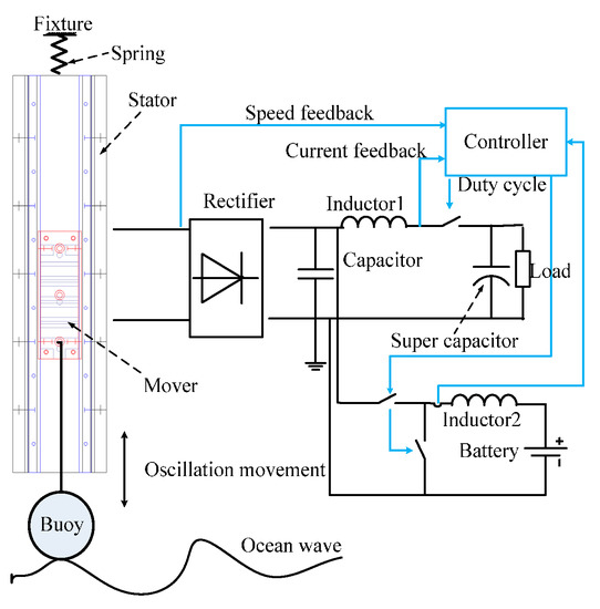
Figure 1.
Schematic blocks of overall wave power generation and storage.
2.2. Prototype of the Linear Machine
The section view of the magnetic path of the machine and its prototype are shown in Figure 2. This machine employs a bilateral structure to counterbalance the normal force of the mover. Both the stator and the mover involve a series of teeth and slots with identical width. The mover consists of two phases creating two sinusoidal currents. PMs are sandwiched by mover plates. As only four PMs are embedded in the mover, the generator is much cheaper than linear permanent magnet synchronized machines that employ many expensive PMs. Since the speed of the ocean wave is relatively low, the width of the teeth for the tested generator is designed as 1 mm so that the generation period of each phase can be relatively small in a short stroke of the machine. The length of the air gap between the mover and the stator can be ensured by eight bearings fixed on the mover. The main specifications of the machine are listed in Table 1.
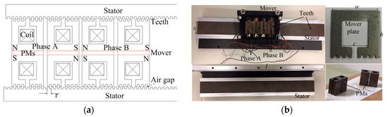
Figure 2.
(a) Sectional view of the magnetic path of the machine and (b) the prototype.

Table 1.
The main specifications of the generator.
2.3. Energy Storage Topology
From the topology of the system given in Figure 3, the storage system includes a supercapacitor and a battery. There are three switches to control the charging current of the storage system. After getting the electricity from the DC bus, the charging current of the supercapacitor can be regulated by the switch of M1. Likewise, by adjusting the duty cycles of M2 and M3, the charging or discharging current of the battery can be controlled. The values of the charging current mainly affect the phase currents of the machine. The controller can calculate a suitable Pulse Width Modulation (PWM) duty for the three switches to achieve a maximal efficiency power generation via the output of the observer which gets the feedback reflecting the status of the generation system and the storage system. Meanwhile, the status of the DC bus and the mechanical input are also observed by the control block to guarantee the steadiness of the whole power generation system.
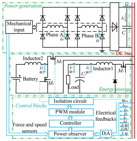
Figure 3.
Topology of the power generation and storage system.
2.4. Main Control Flow Chart of the Whole System
Figure 4 shows the main flow chart of the controller for the power generation system. First, the microprocessor will be initialized after obtaining power from a power supply. The controller gives duty cycles of PWM for switches in accordance with the data from the power observer. The duty cycles to realize power generation with optimal efficiency from the vertical machine will be given.
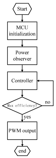
Figure 4.
The main flow chart of the controller for the whole power generation system.
3. Basic Principles of the System
3.1. Mathematical Model of the Linear Machine
The operation principle of the machine is given in Figure 5. Taking phase A as an example, it can be seen that the flux lines go through the mover, the air gap, the stator, and finally back to the original place. Black arrows illustrate the polarizing directions of the PMs. Assuming that the positive and negative terminals of the coils are expressed as e+ and e−, respectively, in Figure 5a, when the mover moves to right direction, the flux lines along the direction shown will be weakened as the magnetic reluctance of the path increases. Therefore, the back electromagnetic force (EMF) of the coil during the first half period can be illustrated as the Figure 5a. Similarly, after the mover shifts 1 mm, the positive and negative terminals of the coil in the second half period can be shown as Figure 5b when the mover moves along the same direction mentioned.
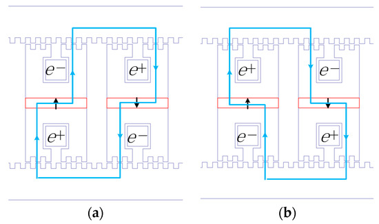
Figure 5.
Operation principle of the machine (a) the first half period and (b) the second half period.
According to Faraday’s law, the back EMF of each phase can be expressed as
where is the flux linkage of a phase and is the flux of the phase. represents the number of turns of the windings and is the displacements of the mover. is the speed of the mover. The back EMF are proportional to and if the change rate of the flux keeps constant. If there is no local saturation for this machine, the flux of each phase without loading can be formulated as [20],
where, and are amplitude of the flux of each phase with respect to the displacement and the length of the pitch to the machine. According to the magnetic path in Figure 5a, its corresponding magnetic circuit can be simplified as Figure 6.
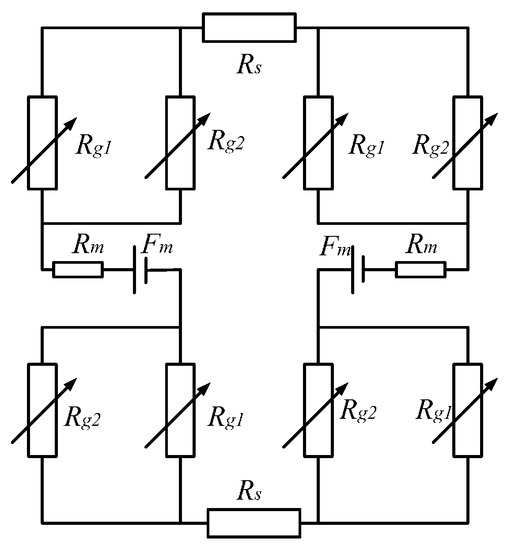
Figure 6.
The equivalent magnetic circuit of a phase.
In this figure, Rs denotes the magnetic reluctance of one stator and Rg1 is the magnetic reluctance of the air gap of teeth at unaligned positions. Rg2 is the reluctance of the air gap at aligned positions. Both Rg1 and Rg2 can be calculated by magnetic tubes or finite element method (FEM). Rm is the sum value of the magnetic reluctances of the mover and the embedded permanent magnet. The main flux that passes the section area of the PM that is vertical to the teeth shown in Figure 5 can be calculated as
Then can be yielded as
3.2. Wave Energy Input
Linear theory of small amplitude fluctuations-based calculation including both kinetic and potential energy can be applied as a mechanical input for the system. The wave surface can be expressed as [21],
where A1 is the amplitude of the wave, x1 is the displacement of the wave with k (number of the wave) as the coefficient and f is the frequency of the wav. the position of a mass point of the wave.
3.3. Characteristics of the Energy Storage System
As for the energy storage system, there are three modes for the whole energy flow listed in Table 2. Assuming that the output of the machine is Po and it is larger than the loading power Pload, the extra energy will be absorbed and stored by a supercapacitor and a battery as shown in Figure 7a. After they are fully charged, switch one will be activated to regulate the power output of the machine. Figure 7b shows that if the loading power is larger than the output of the machine, the switch for charging battery will be closed and the supercapacitor will be discharged to the load. As the loading power increases, both the battery and the supercapacitor will be discharged to the load, which is mode III, as shown in Figure 7c.
Table 2.
Modes of the energy flow.
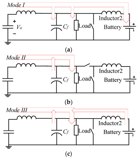
Figure 7.
Three modes of the energy flow of the system (a) supercapacitor and batteries storage; (b) supercapacitor discharge and (c) battery discharge.
3.4. Control Algorithm for the Whole System
To control the voltage of the DC bus, the storage system needs to be regulated based on the load and the status of the machine. The transfer function diagram of the DC bus voltage control can be shown in Figure 8 and a dual-loop control is employed for the power generation system. Gcv(s) and Gci(s) are the controllers of the voltage loop and the current loop, respectively. Gpwm(s), Ki, and Kv denote the gains of the PWM module, the current loop, and the voltage loop, respectively.
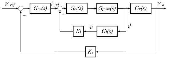
Figure 8.
Transfer function diagram the power storage system.
The storage system can be considered as a bilateral direction convertor (BDC) [22]. From the duty cycle, the transfer functions to output current and output voltage can be expressed as Equations (6) and (7), respectively,
where, L, C, R, and D are respectively the inductance, capacitance, resistance, and damper of the storage system and its loads. The Bode diagram of the two transfer functions is given below, as shown in Figure 9.
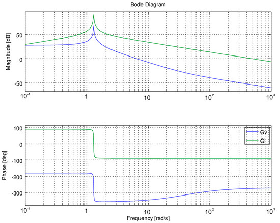
Figure 9.
Bode diagram of the voltage loop and current loop transfer functions.
Since the system is a nonlinear system especially for various loads and there are three modes for the energy flow, the SMC algorithm is used by the current loop and voltage loop of the controller [23]. The dynamic behavior of the energy storage system can be expressed by
where the state vector of the system is and u is the control input of the system.
is the gain of the PWM module. The output error of the voltage with the given reference is
A sliding surface can be found:
On the phase plane , s = 0 is the sliding line which nearly passes through the original point with the slope of , a first-order equation is adapted to represent the sliding mode
and the solution is
If the system’s trajectories can reach the surface of the sliding surface, the following constrain should be guaranteed.
According to Lyapunov’s steadiness condition, one can yield , hence
And the control law of the controller can be obtained
and are constants. is the signal function.
4. FEM Calculation and Simulation
4.1. FEM Calculation for the Machine
The flux distribution of the machine is given in Figure 10. The density of the flux along the teeth aligned with the stator is higher than that of the teeth unaligned, so it obeys the principle mentioned in Figure 5. The B values of the air gap between the mover and the stator vs. the displacement of the mover are calculated as shown in Figure 11. The B value is nearly double that of the teeth shift from unaligned positions to unaligned positions.
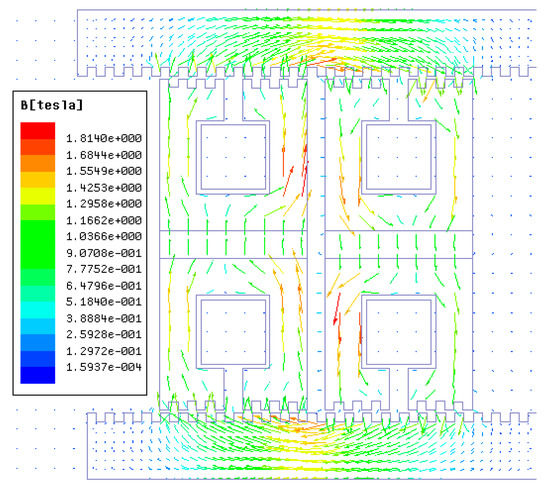
Figure 10.
Flux distribution of the machine.
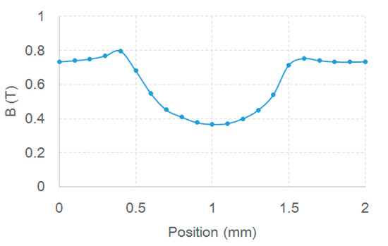
Figure 11.
The B values of the air gap with respect to displacement.
Figure 12 shows the self-inductance of a phase and mutual inductance of an adjacent phase. It can be seen that the self-inductance is about 19.28 mH and the mutual inductance is less than 0.5 mH. Therefore, the mutual inductance can be neglected during the period of the power generation.
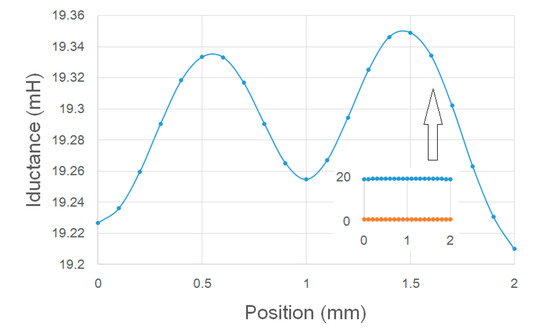
Figure 12.
Self-inductance and mutual inductance of the machine.
4.2. Controller Design for the Whole System
The overall simulation blocks for the controller are shown in Figure 13 and the details of the controller including the main three parameters according to Equation (17) are given in Figure 13b. There are three parameters adjusted by the controller; , and [24]. The control output shows the controller’s output for the control plant, as shown in Figure 14. The control output approaches the sliding surface and then enters the stable state, with the sliding mode output undulating during the whole process. As SMCs are of strong robustness and have fast error convergence for nonlinear systems, they are often employed not only in renewable power generation systems [25], but also in position tracking systems [26]. In literature [27], three control methods including a proportional-integral-derivative (PID) controller, H_infinity controller, and SMC have been compared with energy storage systems. The conclusion suggests that the SMC is better than the PID controller in fast response and tracking accuracy. It can also be seen from Figure 14b that the step responses regulated by a proportional-integral (PI) controller and the SMC are different. Obviously, although the parameters of the PID controller are optimized, the SMC performance is still better, with swift response and low steady state errors.
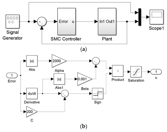
Figure 13.
Simulation blocks for the controller schematic (a) and (b) its constitution.
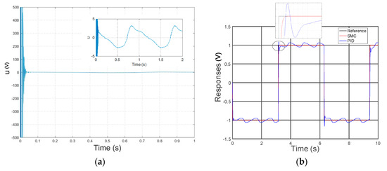
Figure 14.
Output of the controller (a) and the comparison of step responses to a proportional-integral-derivative (PID) controller (b).
4.3. Simulation for the Power Generation System
The open circuit voltage output and flux linkage of the machine are simulated as shown in Figure 15. The amplitude of the speed is 1 m/s. Under this speed, the maximum voltage is up to 12 V and the peak of the flux linkage is around 0.004 Wb. It suggests that the linear machine is capable of producing electricity at such a low speed as 1 m/s. As the speed of the wave is not a constant value, it is necessary to simulate the voltage outputs under different speeds. Figure 15c shows us the voltage outputs of the generator under a variable speed. It can be seen that the voltage outputs would increase with the increase in the wave speed. Since PMs are employed in this machine, there is no need to add an excitation current for each phase of the machine. The efficiency of the power generator could be improved for wave energy harvesting.
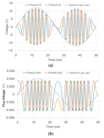
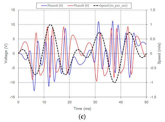
Figure 15.
(a) Open circuit voltage of each phase and (b) corresponding flux linkage under the sinusoid speed with amplitude 1 m/s; (c) voltage output under a variable speed.
The voltage and current outputs of the DC bus under certain loads are shown in Figure 16. The reference voltage is 6 V. It can be seen that the voltage response reaches the reference value with fluctuations under a small load. As the load increases, the voltage trajectory trends to become stable gradually, with the speed gradually declined as shown in Figure 16b. The current is also increased when the load increases.
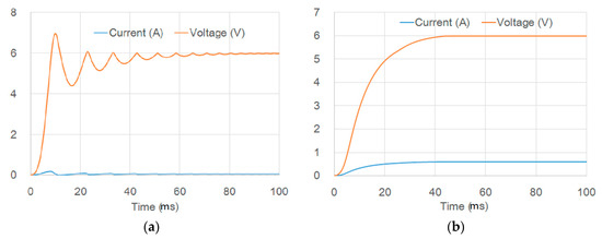
Figure 16.
Simulation voltage and current waveforms with (a) small load and (b) increased load.
The mechanical input and electrical output are calculated via FEM simulations, neglecting the power factor and other strand losses of the machine. Figure 17 shows the phase currents when connecting a resistor of 5 Ω and the electromagnetic force of the machine under a constant speed of 1 m/s. From the simulation results, the square root value of the phase currents is 1.1 A and the average force is around 10 N. Therefore, the mechanical power is 10 W and the electrical output is 6.05 W. The efficiency can be evaluated as 60.5%.
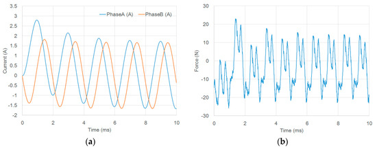
Figure 17.
The machine FEM simulations (a) phase current outputs and (b) electromagnetic force.
5. Efficiency Analysis
The efficiency of the power generation system can be calculated by the following expression [28].
where η accounts for the efficiency and Pout is the power output of the generation system. F and denote the force input and velocity of the mover.
Figure 18 shows the mechanical force input and the power output under the speeds of 0.5 m/s, 1 m/s and 1.5 m/s, and the average force inputs under the three speeds are 20 N, 30 N, and 50 N, respectively. Also, the average power outputs are respectively around 6 W, 19 W, and 45 W. According to the Equation (18), the efficiencies can be calculated under these speeds and all of them are over 60%. Therefore, the efficiency of the proposed power generation method can be 60%, 63.3%, and 64.3%. The efficiency of the proposed power generation is higher than that of traditional approaches for wave energy harvesting.
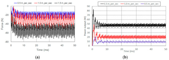
Figure 18.
Analysis under various speeds (a) the electromagnetic forces and (b) power outputs.
6. Experimental Verification
6.1. Experimental Setup
The experimental setup consists the proposed machine, the energy storage system, the dSPACE DS1104 card based controller, and loads, as shown in Figure 19. The SMC is established by using software package MATLAB/Simulink (Mathworks, Natick, MA, USA) interfaced with DS1104, by which the control algorithms coded can be directly downloaded into digital signal processor (DSP) of the card. The mechanical inputs involving the speed of the mover, phase current, and voltage are sampled. The status of the energy storage system, including currents and voltages of the DC bus and each phase can be acquired by analog-to-digital channels of the control board. Mechanical wave motions are simulated by a commercial linear motor, connected with the mover of the proposed machine via a metal rod [29]. Electrical energy is stored in the supercapacitor and then transferred to a battery.
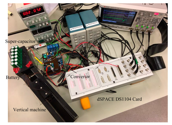
Figure 19.
Experimental setup of the generation and energy storage system.
6.2. Experimental Results
Figure 20 shows the terminal voltage of a phase when this machine works in an inconstant speed. It can be seen that the maximum of the voltage is up to 12 V that is identical to the results from the above simulations. Since the speed is not a sinusoidal one, the amplitude of the voltage from the experiment varies with a variable speed for each stroke, which fulfills the real operation when it is exposed to random ocean waves.
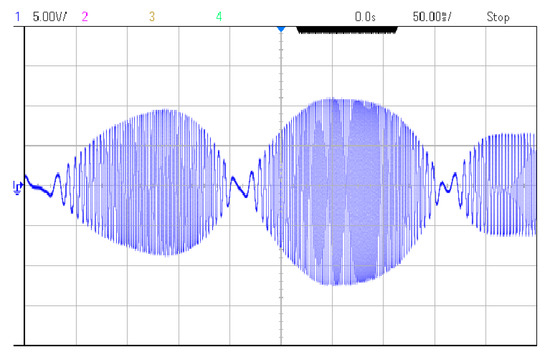
Figure 20.
The terminal voltage of the machine.
By rectifying, the DC voltage and current flowing into the supercapacitor are shown under high speed and low speed, respectively. The voltage output achieves 12 V finally and becomes stable as shown in Figure 21a. The voltage is converted by a constant-voltage and constant-current mode for the charging of the supercapacitor. The maximum output of the voltage is limited at 5 V. Under different speeds from Figure 21b, in which channel 1 is the voltage of the capacitor and channel 2 is its charging current pulses, the charging currents in high speed is more than 2 times higher than the case that the speed is halved to 0.5 m/s, with the maximal value changed from 2 A to a value that is less than 1 A.
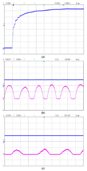
Figure 21.
Supercapacitor voltage (blue) and current (purple) waveforms in speed (a) 1 m/s and (b) 0.5 m/s (c).
From the beginning to a steady state of the whole generator, the voltage and current of the supercapacitor are shown in Figure 22. The voltage grows from zero to the limited voltage of 6 V. The charging current declines from 13 A quickly to nearly 5 A in the middle part and then to zero. More importantly, there is a gap in the current at the beginning due to a pause of the machine and the voltage keeps constant during the gap. After the machine is propelled again, the voltage continues to increase.
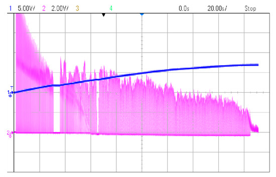
Figure 22.
The voltage (blue) and current (purple) waveforms of the supercapacitor.
When a load is added to the supercapacitor with 1 Ω, the waveforms of the voltages from the DC bus and the supercapacitor and currents of the supercapacitor as well as the load are probed. It can be seen from Figure 23 that the voltage of the supercapacitor drops sharply due to the added load. However, the controller enters mode 3 such that the battery is connected to the DC bus and the sliding mode control method is executed, thus restoring within 1.5 s and keeping the voltage of the DC bus at a constant voltage 5 V. The constant voltage validates the effectiveness of the control method and the robustness of the power generation and the energy storage method.
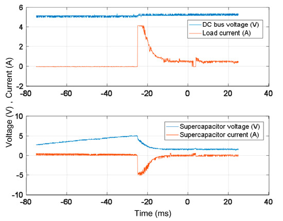
Figure 23.
The voltages of the DC bus and the supercapacitor and the currents from the capacitor and the load.
7. Discussion
As the propulsion of waves in a real ocean is extremely large, the mover should be curved by dampers to avoid its hitting the end of the generator. This investigation needs to be implemented in future to ensure the security of the mechanical devices and the power generation control as well. There are mainly two approaches to design the damping device. Mechanically, a spring shown in Figure 1 is able to alleviate an apparent crash when the mover approaches the end of the generator. The Hooker coefficient of the spring can be adjusted in accordance with the movements of real ocean waves. Another way is to adjust the electric loads of the power generation system, an effective approach to control the phase currents [30]. Consequently, the electromagnetic force from the mover could be controlled and the motion of the mover can be also governed by adding or reducing loads, or by including supercapacitors and batteries. The two approaches will be carried out by following-up investigations.
8. Conclusions
In order to realize an oscillating wave power generator under low speeds, this paper has presented a vertical machine operating in the low-speed environment. Combined with the energy storage system, three modes for the power generation system have been proposed. Also, a sliding mode controller is designed for the whole system to ensure the voltage output in the DC bus. The main contributions of this paper are summarized as follows.
- (1)
- Low-speed oscillating wave power generation is realized by the effective direct-drive approach;
- (2)
- A bilateral vertical machine is effectively designed for low-speed wave power generation;
- (3)
- An energy storage method using a supercapacitor and a battery has been proposed for wave power harvesting with three modes;
- (4)
- The sliding mode control operates effectively to improve the performance of the generation system;
- (5)
- The efficiency of the power conversion is evaluated and analyzed. Compared with other OWCs, this efficiency is higher in the paper.
The effectiveness and the feasibility of the system have been validated by theoretical analyses, simulations, and experiments simultaneously. It is expected that this oscillating power generation system can be widely used for wave power harvesting in the future.
Acknowledgments
The authors gratefully acknowledge the support of Research Committee of the Hong Kong Polytechnic University under the project reference G-YN27.
Author Contributions
Yu Zou developed the analysis, hardware design and measurement. He also conducted the simulation of the work. Ka Wai Eric Cheng was responsible for the background theory. He also provided the guidance and supervision of the study.
Conflicts of Interest
The authors declare no conflict of interest.
References
- Bhattacharyya, R.; McCormick, M.E. Wave Energy Conversion, Ocean Engineering Series; Elsevier: London, UK, 2003. [Google Scholar]
- Scruggs, J.; Jacob, P. Harvesting ocean wave energy. Science 2009, 323, 1176–1178. [Google Scholar] [CrossRef] [PubMed]
- Ahmed, T.; Nishida, K.; Nakaoka, M. Grid power integration technologies for offshore ocean wave energy. In Proceedings of the 2010 IEEE Energy Conversion Congress and Exposition Conference, Atlanta, GA, USA, 12–16 September 2010; pp. 2378–2385. [Google Scholar]
- Mendonça, H.; Martinez, S. A Resistance Emulation Approach to Optimize the Wave Energy Harvesting for a Direct Drive Point Absorber. IEEE Trans. Sustain. Energy 2016, 7, 3–11. [Google Scholar] [CrossRef]
- O’Sullivan, D.L.; Lewis, A.W. Generator selection and comparative performance in offshore oscillating water column ocean wave energy converters. IEEE Trans. Energy Convers. 2011, 26, 603–614. [Google Scholar] [CrossRef]
- Henderson, R. Design, simulation, and testing of a novel hydraulic power take-off system for the Pelamis wave energy converter. Renew. Energy 2006, 31, 271–283. [Google Scholar] [CrossRef]
- Wave Dragon Official Web Site. Available online: www.wavedragon.net (accessed on 8 June 2007).
- Polinder, H.; Damen, M.E.C.; Gardner, F. Linear PM generator system for wave energy conversion in the AWS. IEEE Trans. Energy Convers. 2004, 19, 583–589. [Google Scholar] [CrossRef]
- Richter, M.; Magaña, M.E.; Sawodny, O.; Brekken, T.K.A. Nonlinear Model Predictive Control of a Point Absorber Wave Energy Converter. IEEE Trans. Sustain. Energy 2013, 4, 118–126. [Google Scholar] [CrossRef]
- Amann, K.U.; Magaña, M.E.; Sawodny, O. Model Predictive Control of a Nonlinear 2-Body Point Absorber Wave Energy Converter with Estimated State Feedback. IEEE Trans. Sustain. Energy 2015, 6, 336–345. [Google Scholar] [CrossRef]
- Alnajjab, B.; Blum, R.S. Estimating Waveforms of Ocean Waves to Enhance the Efficiency of Ocean Energy Conversion. IEEE Trans. Sustain. Energy 2017, 8, 179–191. [Google Scholar] [CrossRef]
- Polinder, H.; Mecrow, B.C.; Jack, A.G.; Dickinson, P.G.; Mueller, M.A. Conventional and TFPM linear generators for direct-drive wave energy conversion. IEEE Trans. Energy Convers. 2005, 20, 260–267. [Google Scholar] [CrossRef]
- Prudell, J.; Stoddard, M.; Amon, E.; Brekken, T.K.A.; Jouann, A. A permanent-magnet tubular linear generator for ocean wave energy conversion. IEEE Trans. Ind. Appl. 2010, 46, 2392–2400. [Google Scholar] [CrossRef]
- Feng, N.; Yu, H.; Hu, M.; Liu, C.; Huang, L.; Shi, Z. A Study on a Linear Magnetic-Geared Interior Permanent Magnet Generator for Direct-Drive Wave Energy Conversion. Energies 2016, 9, 487. [Google Scholar] [CrossRef]
- Vermaak, R.; Kamper, M.J. Design Aspects of a Novel Topology Air-Cored Permanent Magnet Linear Generator for Direct Drive Wave Energy Converters. IEEE Trans. Ind. Electron. 2012, 59, 2104–2115. [Google Scholar] [CrossRef]
- Pan, J.; Zou, Y.; Cao, G. Investigation of a low-power, double-sided switched reluctance generator for wave energy conversion. IET Renew. Power Gener. 2013, 7, 98–109. [Google Scholar] [CrossRef]
- Xue, X.D.; Cheng, K.W.E.; Ho, S.L. A Self-Training Numerical Method to Calculate the Magnetic Characteristics for Switched Reluctance Motor Drives. IEEE Trans. Magn. 2004, 40, 734–737. [Google Scholar] [CrossRef]
- Huang, L.; Yu, H.; Hu, M.; Zhao, J.; Cheng, Z. A Novel Flux-Switching Permanent-Magnet Linear Generator for Wave Energy Extraction Application. IEEE Trans. Magn. 2011, 47, 1034–1037. [Google Scholar] [CrossRef]
- Pan, J.; Or, S.W.; Zou, Y.; Cheung, N.C. Sliding-mode position control of medium-stroke voice coil motor based on system identification observer. IET Electr. Power Appl. 2015, 9, 620–627. [Google Scholar] [CrossRef]
- Hong, Y.; Eriksson, M.; Castellucci, V.; Boström, C.; Waters, R. Linear generator-based wave energy converter model with experimental verification and three loading strategies. IET Renew. Power Gener. 2016, 10, 349–359. [Google Scholar] [CrossRef]
- Fitzgerald, A.E.; Kingsley, C. Electric Machinery; McGraw-Hill Press: London, UK, 2003. [Google Scholar]
- Thang, T.V.; Ahmed, A.; Kim, C.; Park, J.H. Flexible System Architecture of Stand-Alone PV Power Generation with Energy Storage Device. IEEE Trans. Energy Convers. 2015, 30, 1386–1396. [Google Scholar] [CrossRef]
- Chen, K.Y. Sliding Mode Minimum-Energy Control for a Mechatronic Motor-Table System. IEEE/ASME Trans. Mechatron. 2016, 21, 1487–1495. [Google Scholar] [CrossRef]
- Barambones, O.; Alkorta, P. Position Control of the Induction Motor Using an Adaptive Sliding-Mode Controller and Observers. IEEE Trans. Ind. Electron. 2014, 61, 6556–6565. [Google Scholar] [CrossRef]
- Toloue, S.F.; Moallem, M. Multivariable Sliding-mode Extremum Seeking Control with Application to MPPT of an Alternator-based Energy Conversion System. IEEE Trans. Ind. Electron. 2017. [Google Scholar] [CrossRef]
- Abd El Khalick, M.A.M.; Uchiyama, N.; Sano, S. Energy Saving in Feed Drive Systems Using Sliding-Mode-Based Contouring Control with a Nonlinear Sliding Surface. IEEE/ASME Trans. Mechatron. 2015, 20, 572–579. [Google Scholar]
- Ortega, Á.; Milano, F. Modeling, Simulation, and Comparison of Control Techniques for Energy Storage Systems. IEEE Trans. Power Syst. 2017, 32, 2445–2454. [Google Scholar] [CrossRef]
- Pan, J.F.; Zou, Y.; Cheung, N.; Cao, G.Z. The direct-drive sensorless generation system for wave energy utilization. Int. J. Electr. Power Energy Syst. 2014, 62, 29–37. [Google Scholar] [CrossRef]
- Pan, J.F.; Zou, Y.; Cheung, N.; Cao, G.Z. On the Voltage Ripple Reduction Control of the Linear Switched Reluctance Generator for Wave Energy Utilization. IEEE Trans. Power Electron. 2014, 29, 5298–5307. [Google Scholar] [CrossRef]
- Bostrom, C.; Leijon, M. Operation analysis of a wave energy converter under different load conditions. IET Renew. Power Gener. 2011, 5, 245–250. [Google Scholar] [CrossRef]
© 2017 by the authors. Licensee MDPI, Basel, Switzerland. This article is an open access article distributed under the terms and conditions of the Creative Commons Attribution (CC BY) license (http://creativecommons.org/licenses/by/4.0/).