Abstract
The complex three-dimensional relationships in congenital craniofacial reconstruction uniquely lend themselves to the ability to accurately plan and model the result provided by computer-aided design and manufacturing (CAD/CAM). The goal of this study was to illustrate indications where CAD/CAM would be helpful in the treatment of congenital craniofacial anomalies reconstruction and to discuss the application of this technology and its outcomes. A retrospective review was performed of all congenital craniofacial cases performed by the senior author between 2010 and 2014. Cases where CAD/CAM was used were identified, and illustrative cases to demonstrate the benefits of CAD/CAM were selected. Preoperative appearance, computerized plan, intraoperative course, and final outcome were analyzed. Preoperative planning enabled efficient execution of the operative plan with predictable results. Risk factors which made these patients good candidates for CAD/CAM were identified and compiled. Several indications, including multisuture and revisional craniosynostosis, facial bipartition, four-wall box osteotomy, reduction cranioplasty, and distraction osteogenesis could benefit most from this technology. We illustrate the use of CAD/CAM for these applications and describe the decision-making process both before and during surgery. We explore why we believe that CAD/CAM is indicated in these scenarios as well as the disadvantages and risks.
Congenital craniofacial anomalies present a unique challenge due to future skeletal growth and soft tissue changes. These factors force the craniofacial surgeon to extend beyond three-dimensional (3D) planning and develop a four-dimensional, temporal perspective. In current craniofacial practice, repairs often require intraoperative decision making without controlled objective planning. Outcomes have been contingent upon the ability of the surgeon to predict patterns of growth, envision a successful outcome, and execute a surgical plan. Historically, this was largely guided by two-dimensional images, 3D cast models, or determined intraoperatively.
The development of computer-aided design and manufacturing (CAD/CAM) for virtual surgical planning (VSP) has enabled preoperative planning in three dimensions. In addition, the virtual surgical plan can be modeled and the outcomes analyzed for longitudinal form and function. Since the surgical plan is developed in a virtual environment, an unlimited number of iterations can be analyzed until the desired outcome is achieved. There is no penalty for trial and error. As the attempted repair becomes more difficult and the number of bone segments that require manipulation increases, CAD/CAM becomes increasingly beneficial for obtaining the best outcome.
In addition to virtual planning, this technology enables manufacturing of guides and models for intraoperative use. These cutting guides can be used to make precise osteotomies based on the virtual plan. They can help avoid crucial underlying structures such as the dural venous sinuses, injury to which is a significant risk in these operations []. Surgical models provide 3D references in the operating room. The combination of these tools can minimize the amount of time spent contouring bone intraoperatively to obtain the precise fit. Indeed, the execution of the virtual plan leads to tight tolerances and minimizes the need for free-hand contouring.
From the large repertoire of common craniofacial reconstructions, we believe that multisuture craniosynostosis repair or revision following craniosynostosis repair, facial bipartition, four-wall box osteotomies, reduction cranioplasty, and distraction osteogenesis benefit most from CAD/CAM technology. In this overview, we describe the application of CAD/CAM for these procedures and discuss specific indications, which may suggest that CAD/CAM may be of benefit for their execution. The basic theory and use of CAD/CAM for surgical planning is well described in the surgical literature and will not be mentioned.
Materials and Methods
A retrospective review was performed of all congenital craniofacial cases performed at the Johns Hopkins Hospital by the senior author (A.H.D.) between 2010 and 2014. This study was approved by the Johns Hopkins Hospital Institutional Review Board. Cases where CAD/CAM was used were identified, and illustrative cases to demonstrate the benefits of CAD/CAM were selected.
Cases
Multisuture Craniosynostosis
Multisuture craniosynostosis repair is a 3D puzzle of calvarial pieces that must be cut and rearranged to achieve the desired shape. In the late 1980s, the first 3D reconstructions of computed tomography (CT) scans became available for assessment and surgical correction of craniosynostosis []. For the first time, the surgeon could evaluate the entire calvarium and visualize the relationships of the cranial bones and sutures. Due to the progressive implementation of resorbable hardware [,,,] and ultrasonic welding [,], perioperative and long-term outcomes have steadily improved []. Even so, the highly variable anatomy and necessity for multiple osteotomies make planning difficult and imprecise. Although major osteotomy sites can be planned preoperatively, their exact locations still have to be determined in the operating room. In addition, calvarial reconstruction for patients with multisuture craniosynostosis often requires several osteotomies producing calvarial puzzle pieces, which must then be fit together. CAD/CAM allows for an unlimited number of attempts to solve this puzzle and can provide cutting and positioning guides to transfer the plan into the operating room.
Case
A 2-month-old male presented with sagittal and left unicoronal craniosynostosis with significant plagiocephaly. Initial repair was performed in the standard fashion, however, at the age of 2 years, he was noted to develop secondary turricephaly and recurrent left unilateral frontal bar retrusion (Figure 1). VSP was used to plan the secondary reconstruction.
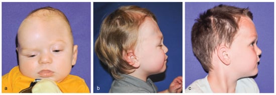
Figure 1.
(a) Preoperative frontal view of a 2-month-old male presenting with sagittal and left unicoronal craniosynostosis. Subsequently underwent traditional craniosynostosis surgery at 5 months of age. (b) Lateral view, 2 years postoperatively. Patient had developed secondary turricephaly and recurrent unilateral frontal bar retrusion along the left unicoronal site. (c) Lateral view, 1 year and 4 months (age 4) after revision surgery utilizing CAD/CAM technology.
Virtual planning began with cutting of the supraorbital bandeau in the standard fashion. The bandeau was then virtually split, and the unaffected hemibandeau mirrored to design and shape the affected side. The bandeau was virtually repositioned, rotated, and advanced. The final position was “overcorrected” as allowed by the soft tissue envelope to accommodate future growth. The calvarium was superimposed onto the forehead to determine the best-fit bifrontal craniotomy bone graft site. An age-matched control skull (based on a dataset of “normal” head CTs) was used as an overlay to help establish normal calvarial height and width (Video 1).
CAD/CAM for multisuture craniosynostosis. Virtual surgical planning was used to plan calvarial osteotomies and to model the final result.
In the operating room, the cranial vault was accessed through a standard coronal incision and a subgaleal dissection was performed, taking care to preserve the pericranium. Frontal and parietal bone cutting guides were placed on the cranium and the proposed osteotomies were marked. The cutting guides were manufactured to highlight the planned osteotomies as well as the locations of the dural venous sinuses to ensure safety. The supraorbital bandeau was exposed and free-hand osteotomies were performed. A positioning guide was then used to create the final construct consisting of the new supraorbital bandeau and frontal bone pieces. The construct was secured to the skull base using resorbable plates and screws. Remaining calvarial bone pieces and particulate bone graft were used to fill the donor site areas (Figure 1).
Facial Bipartition
Initially described by Tessier to treat hypertelorism [] and popularized by Kawamoto et al. [] facial bipartition has become a versatile tool in the craniofacial surgeon’s toolbox. However, facial bipartition adds an additional layer of complexity and to date has had limited objective measures for intraoperative decision making. The outcome depends on the final position of the segments and has significant soft tissue symmetry implications. Symmetry traditionally has been assessed by visual inspection in the operating room, and edge-to-edge bony contact is obtained by intraoperative contouring of the facial segments. Asymmetric bipartitions have an even higher degree of variability since symmetry cannot be used as a visual guide.
VSP has several unique advantages as applied to facial bipartition. First, cutting guides based on CT data prevent damage to the intramaxillary permanent teeth. In addition, the ability to virtually mirror one side improves symmetry, and the use of cutting and positioning guides enable maximal bony contact and minimize the need for bone grafting. The angles and distances of movement can be precisely calculated to correct vertical dystopias. Finally, multiple objective measures of accepted cephalometric points may be assessed within the virtual surgical environment for a controlled planned resection, thereby generating a precisely modeled result that can be predictably reproduced in the operating room.
Case
A 5-year-old female patient presented with heminasal agenesis and hypertelorism. VSP was used to plan facial bipartition with periorbital osteotomies. The position of the intramaxillary teeth was noted and osteotomies were planned around them to avoid damage. By manipulating the bone segments, precise osteotomies could be planned to obtain an accurate and aesthetic final result (Figure 2). Symmetry was assured by real-time measurements and mirroring of one side on the other. CAD enabled visualization of the surgical outcome and modification of the surgical plan in real time based on this feedback. CAM enabled transfer of the virtual plan into the operating room, ensuring that the midline osteotomies were precisely executed according to the plan. This ensured excellent bony contact. A forehead flap was later used to reconstruct the heminasal agenesis [].
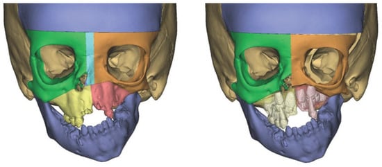
Figure 2.
A 5-year-old patient with heminasal agenesis and hypertelorism (left). VSP was used to plan facial bipartition with periorbital osteotomies (right). The position of the intramaxillary teeth was noted and osteotomies were planned around them to avoid damage. Symmetry was assured by real-time measurements and mirroring of one side on the other.
Four-Wall Box Osteotomy
While similar to facial bipartition, the extra mobility of the four-wall box technique introduces increased complexity. Performing the LeFort I osteotomy in a child before permanent tooth eruption increases the risk of damage to intramaxillary teeth. CAD/CAM enables virtual visualization of teeth and precise osteotomy planning to minimize this risk. In addition, the angles and plane of translocation of the orbits can be measured to ensure symmetry, correct dystopia, and create aesthetic harmony. Measurements such as dacryon-to-dacryon distance can be obtained throughout the planning process to secure the best possible outcome. Likewise, the cant of the orbits can be measured and planned to correct vertical dystopia. Finally, one can attempt to predict the changes that will occur to the overlying soft tissue due to manipulation of the bony segments [].
Case
A 9-year-old male presented with cleidocranial dysplasia. Upon examination, the patient had macrocephaly and a large open anterior fontanelle. In addition, he was noted to have frontal bossing and marked hypertelorism. The patient’s maxilla and occlusion were unaffected, and therefore, the decision was made to perform a four-wall box osteotomy to correct the frontal bossing and hypertelorism. A standard four-wall box osteotomy was performed; however, cutting guides were used for the bifrontal and midline craniotomies. Additional cutting guides were used to shape the frontal bone segments on the back table before securing it in place with titanium plates (Figure 3).
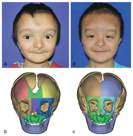
Figure 3.
(a) Frontal view of a 9-year-old male with cleidocranial dysplasia. (b) Three-dimensional skull model illustrating congenital macrocephaly, a large open anterior fontanelle, frontal bossing, and marked hypertelorism. (c) CAD was used to plan osteotomies to avoid intramaxillary teeth and vital structures. (d) Frontal view 3 months after four-wall box osteotomy using CAD/CAM technology.
Reduction Cranioplasty
Reductive cranioplasty is a high-risk procedure due to large fluid shifts, exposure of large areas of brain, and the potential for significant blood loss. Traditionally, significant operative time was spent contouring cranial bone segments to obtain the best possible fit and reduction. This resulted in prolonged exposure to anesthesia and increased surgical risk. CAD/CAM enables meticulous osteotomy planning to create the final calvarial construct. Cutting and positioning guides then transpose the plan into the operating room to enable a precise and time-efficient operation.
Case
A 7-year-old male presented with a head circumference of 67 cm and skin breakdown due to hydrocephalus which was untreated until the age of 3 years. Reduction cranioplasty was planned to reduce calvarial size and increase head mobility.
Virtual planning of reduction cranioplasty begins by cutting and posteriorly rotating the supraorbital bandeau. A virtual bifrontal craniotomy is performed, and the temporoparietal occipital bone pieces are virtually manipulated with a combination of translation, rotation, and transposition to reduce the calvarial height and to minimize the congenital calvarial defect (Figure 4). Burr holes are planned with respect to the final construct and to avoid potential injury to the sagittal or transverse sinuses. Based on the VSP, cutting guides with markings denoting the sagittal sinus, positioning guides, and preoperative and postoperative stereolithographic models are generated.
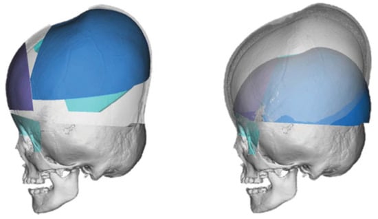
Figure 4.
Virtual segments of the preoperative skull were defined and manipulated to create a new, smaller calvarium (left). Comparison of preoperative appearance and planned postoperative appearance based on the virtual surgical plan (right).
A standard coronal incision was performed and dissection performed in the subgaleal plane, preserving the pericranium. The periorbita were dissected from the supraorbital roof. Calvarial cutting guides were then placed onto the scalp, and planned osteotomies were marked. The sagittal sinus was also marked, and burr holes drilled in their planned locations away from the sinus. The marked osteotomies were completed. Next, the temporalis muscle was partially elevated to allow placement of the supraorbital bandeau cutting guide and completion of the osteotomies.
On the back table, positioning guides were used to reorient the bone segments and allow accurate fixation with bioabsorbable plates and screws. Thus, the superior orbital roofs, rims, forehead, and subtotal calvarium were reconstructed to replicate the preoperative VSP. Before reattaching the completed calvarium, barrel stave osteotomies were performed in the basicranium, specifically of the temporal bones, to allow for passive reduction and several triangular pieces of bone were removed to allow for reduction of bitemporal width. The fronto-orbital bandeau and the reshaped calvarium were then reattached to the cranial base using bioabsorbable plates and screws. Stereolithographic models were used to confirm satisfactory reconstruction before reattachment of the skull. A subgaleal drain was placed, followed by a layered soft tissue closure.
Distraction Osteogenesis
Initially introduced for limb lengthening [], distraction osteogenesis was first described for mandibular lengthening by McCarthy et al. in 1992 []. Although limb lengthening strives to eliminate any movement beyond a single vector in the direction of the limb, craniofacial distraction deals with complex movements which can involve multiple vectors. Thus, distraction mechanisms are placed to obtain a precise position goal. This position is dependent on the type of distractor and, most importantly, on the position and angle of the distractor. VSP can uniquely estimate the final position of the distracted segment and plan the correct vectors and distractor position to obtain the desired result.
Case
A 33-month-old male born with Pierre Robin sequence presented with turribrachycephaly after having undergone repair of multisuture craniosynostosis 2 years prior at an outside institution. A plan for posterior cranial vault expansion using distraction osteogenesis was developed (Figure 5). The prior coronal incision was used to access the calvarium. Using the manufactured cutting guides, craniotomies were performed to release the posterior cranial vault as a single unit. Once mobility of the unit was assured, bilateral distractors were placed using preplanned models to assure symmetry and correct placement. Distraction was performed at a rate of 2 mm per day until 3 cm of distraction was achieved.
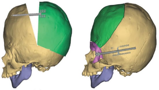
Figure 5.
Computer modeling was used to predict the final position of the distracted segment and to plan the correct placement and vector of the distractor for cranial vault remodeling (left). Subsequently, an additional plan for fronto-orbital advancement was created with internal distraction devices placed at each of the frontozygomatic suture lines (right).
Three months after distractor placement, the distractors were removed. After developing a new VSP for fronto-orbital advancement using distraction osteogenesis, an anterior craniotomy was performed using the manufactured cutting guides. Additional superior fronto-orbital and zygomatic osteotomies were performed. After contouring of the frontal bone segment, internal distraction devices were placed at each of the frontozygomatic suture lines using the positioning guides. Based on the calculated positions and vectors, these distractors produced advancement as well as clockwise rotation. Distraction was performed at 1 mm per day for a total of 20 mm of distraction.
Discussion
We demonstrate the application and outcome of VSP in the repair of complex congenital craniofacial defects. CAD/CAM is an emerging technology, and since surgeons first started using it for orthognathic surgery [], its use gradually expanded to include head and neck reconstruction with the free-fibula flap []. These applications demonstrate the feasibility, accuracy, and cost effectiveness of using CAD/CAM for their planning and execution. We have also previously demonstrated the successful use of CAD/CAM for craniosynostosis [] and reduction cranioplasty [].
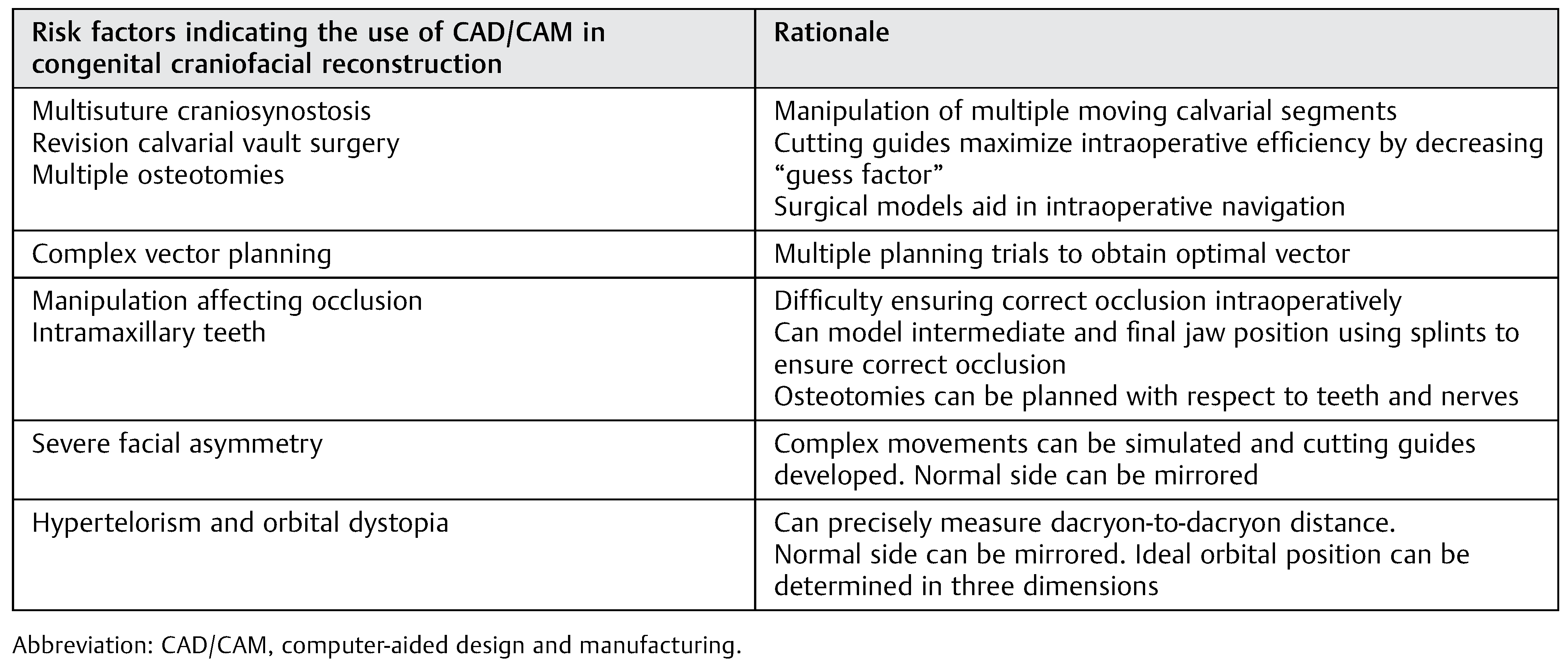
Of the vast array of craniofacial interventions, we demonstrate five cases where VSP is particularly useful in obtaining a favorable aesthetic and functional outcome. We introduce the specific criteria we used to include these cases, and believe that these criteria can serve as indications for the use of CAD/CAM in congenital craniofacial reconstruction (Table 1). We believe that the use of CAD/CAM in these cases may be helpful; however, this list is neither definitive nor exhaustive. As CAD/CAM continues to develop, it will likely expand.

Table 1.
Risk factors indicating the use of CAD/CAM in congenital craniofacial reconstruction.
The advantages of CAD/CAM are numerous. They include the ability to virtually manipulate skeletal segments and analyze the expected outcome to obtain the best possible result. This is complimented by the opportunity for an unlimited number of trials achieved by hitting “reset” on the screen. Once the surgical plan is developed and objectively analyzed, it can then be translated into the operating room by computer-manufactured guides and models. With the use of sterile cutting guides, “eyeballing” and “free-handing” are eliminated, and each cut and construct is as precise as the computer model. Vital underlying structures, particularly the dural venous sinuses, are avoided.
As with any new technology, there are disadvantages as well. Expense is becoming an increasingly important factor in health care decision making; every additional expense must be justified and proven. Currently, VSP is a partnership between industry and the surgeon—the planning is performed by an engineer under the guidance on the physician, and the models are manufactured by the contracted company. With the emergence and popularization of 3D printers, these duties can one day be performed in the office on an as-needed basis. This would require either learning CAD or hiring an engineer to work directly within the department or division. These expenses could then be shared among several surgeons to potentially lower cost and increase adoption.
Although several authors have illustrated time saved in the operating room, VSP requires additional time spent during preoperative planning. In our experience, planning sessions require anywhere from 20 to 60 min, with an average of 30 to 45 min spent. In the majority of cases, a single planning sessions is sufficient to develop the surgical plan; however, additional sessions may be required for complex cases.
Despite the exciting potential of this new technology, it is important to remember that computer models cannot substitute for intraoperative decisions making. It is crucial to understand when to deviate away from the premade plan due to concerns for safety or other factors that may spontaneously arise.
Conclusion
CAD/CAM has been propelled into practice by excitement and potential. We believe that there are several surgical procedures where the application of CAD/CAM particularly benefits the patient and surgeon. Of the surgical interventions that are most likely to show an improvement in patient outcomes with the adoption of CAD/CAM, complex congenital craniofacial procedures have the greatest potential. The large number of osteotomies, manipulation of multiple segments, influence of skeletal growth, and historical dependence on time-consuming intraoperative decisions make these interventions especially suited for the planning and precision offered by CAD/CAM. For the craniofacial surgeon looking to implement CAD/CAM technology into their surgical practice, applying it to these indications (Table 1) will likely yield the greatest benefit to patient and surgeon.
We illustrate the five craniofacial procedures that we believe most benefit from CAD/CAM, and the specific indications which may be used to assess the need for computerized planning. Although the value of CAD/CAM in these cases is evident, further study is required to quantify and validate its use.
References
- Neligan, P.; Warren, R.J.; Van Beek, A. Plastic Surgery, 3rd ed; Elsevier Saunders: London; New York, 2013. [Google Scholar]
- Marsh, J.L.; Vannier, M.W. The anatomy of the cranio-orbital deformities of craniosynostosis: insights from 3-D images of CT scans. Clin Plast Surg 1987, 14, 49–60. [Google Scholar] [CrossRef] [PubMed]
- Kurpad, S.N.; Goldstein, J.A.; Cohen, A.R. Bioresorbable fixation for congenital pediatric craniofacial surgery: a 2-year follow-up. Pediatr Neurosurg 2000, 33, 306–310. [Google Scholar] [CrossRef] [PubMed]
- Losken, A.; Williams, J.K.; Burstein, F.D.; et al. Outcome analysis for correction of single suture craniosynostosis using resorbable fixation. J Craniofac Surg 2001, 12, 451–455, discussion 456–457. [Google Scholar] [CrossRef] [PubMed]
- Ahmad, N.; Lyles, J.; Panchal, J.; Deschamps-Braly, J. Outcomes and complications based on experience with resorbable plates in pediatric craniosynostosis patients. J Craniofac Surg 2008, 19, 855–860. [Google Scholar] [CrossRef] [PubMed]
- Eppley, B.L.; Morales, L.; Wood, R.; et al. Resorbable PLLA-PGA plate and screw fixation in pediatric craniofacial surgery: clinical experience in 1883 patients. Plast Reconstr Surg 2004, 114, 850–856, discussion 857. [Google Scholar] [CrossRef] [PubMed]
- Arnaud, E.; Renier, D. Pediatric craniofacial osteosynthesis and distraction using an ultrasonic-assisted pinned resorbable system: a prospective report with a minimum 30 months’ follow-up. J Craniofac Surg 2009, 20, 2081–2086. [Google Scholar] [CrossRef] [PubMed]
- Eckelt, U.; Nitsche, M.; Müller, A.; Pilling, E.; Pinzer, T.; Roesner, D. Ultrasound aided pin fixation of biodegradable osteosynthetic materials in cranioplasty for infants with craniosynostosis. J Craniomaxillofac Surg 2007, 35, 218–221. [Google Scholar] [CrossRef] [PubMed]
- Seruya, M.; Oh, A.K.; Boyajian, M.J.; et al. Long-term outcomes of primary craniofacial reconstruction for craniosynostosis: a 12-year experience. Plast Reconstr Surg 2011, 127, 2397–2406. [Google Scholar] [CrossRef] [PubMed]
- Tessier, P. Marchac, D., Ed.; Facial bipartition: a concept more than a procedure. In Craniofacial Surgery; Springer: Berlin, Heidelberg:, 1978; pp. 217–245. [Google Scholar]
- Kawamoto, H.K.; Heller, J.B.; Heller, M.M.; et al. Craniofrontonasal dysplasia: a surgical treatment algorithm. Plast Reconstr Surg 2007, 120, 1943–1956. [Google Scholar] [CrossRef] [PubMed]
- Fisher, M.; Zelken, J.; Redett, R.J. Heminasal agenesis: a reconstructive challenge. J Craniofac Surg 2014, 25, e239–e241. [Google Scholar] [CrossRef] [PubMed]
- Kaipatur, N.R.; Flores-Mir, C. Accuracy of computer programs in predicting orthognathic surgery soft tissue response. J Oral Maxillofac Surg 2009, 67, 751–759. [Google Scholar] [CrossRef] [PubMed]
- Codivilla, A. On the means of lengthening, in the lower limbs, the muscles and tissues which are shortened through deformity. J Bone Joint Surg 1905, 2, 353–369. [Google Scholar] [CrossRef] [PubMed]
- McCarthy, J.G.; Schreiber, J.; Karp, N.; Thorne, C.H.; Grayson, B.H. Lengthening the human mandible by gradual distraction. Plast Reconstr Surg 1992, 89, 1–8, discussion 9–10. [Google Scholar] [CrossRef] [PubMed]
- Cutting, C.; Grayson, B.; Bookstein, F.; Fellingham, L.; McCarthy, J.G. Computer-aided planning and evaluation of facial and orthognathic surgery. Clin Plast Surg 1986, 13, 449–462. [Google Scholar] [CrossRef] [PubMed]
- Seruya, M.; Fisher, M.; Rodriguez, E.D. Computer-assisted versus conventional free fibula flap technique for craniofacial reconstruction: an outcomes comparison. Plast Reconstr Surg 2013, 132, 1219–1228. [Google Scholar] [CrossRef] [PubMed]
- Seruya, M.; Borsuk, D.E.; Khalifian, S.; Carson, B.S.; Dalesio, N.M.; Dorafshar, A.H. Computer-aided design and manufacturing in craniosynostosis surgery. J Craniofac Surg 2013, 24, 1100–1105. [Google Scholar] [CrossRef] [PubMed]
- Dorafshar, A.; Fisher, M.; Borsuk, D.; Fishman, E.; Ahn, E. A novel application of computer-aided design and manufacturing for reduction cranioplasty. J Craniofac Surg 2014, 25, 172–176. [Google Scholar] [CrossRef] [PubMed]
© 2016 by the author. The Author(s) 2016.