


A Software Platform for Quadruped Robots with Advanced Manipulation Capabilities


Abstract
:1. Introduction
2. Related Work
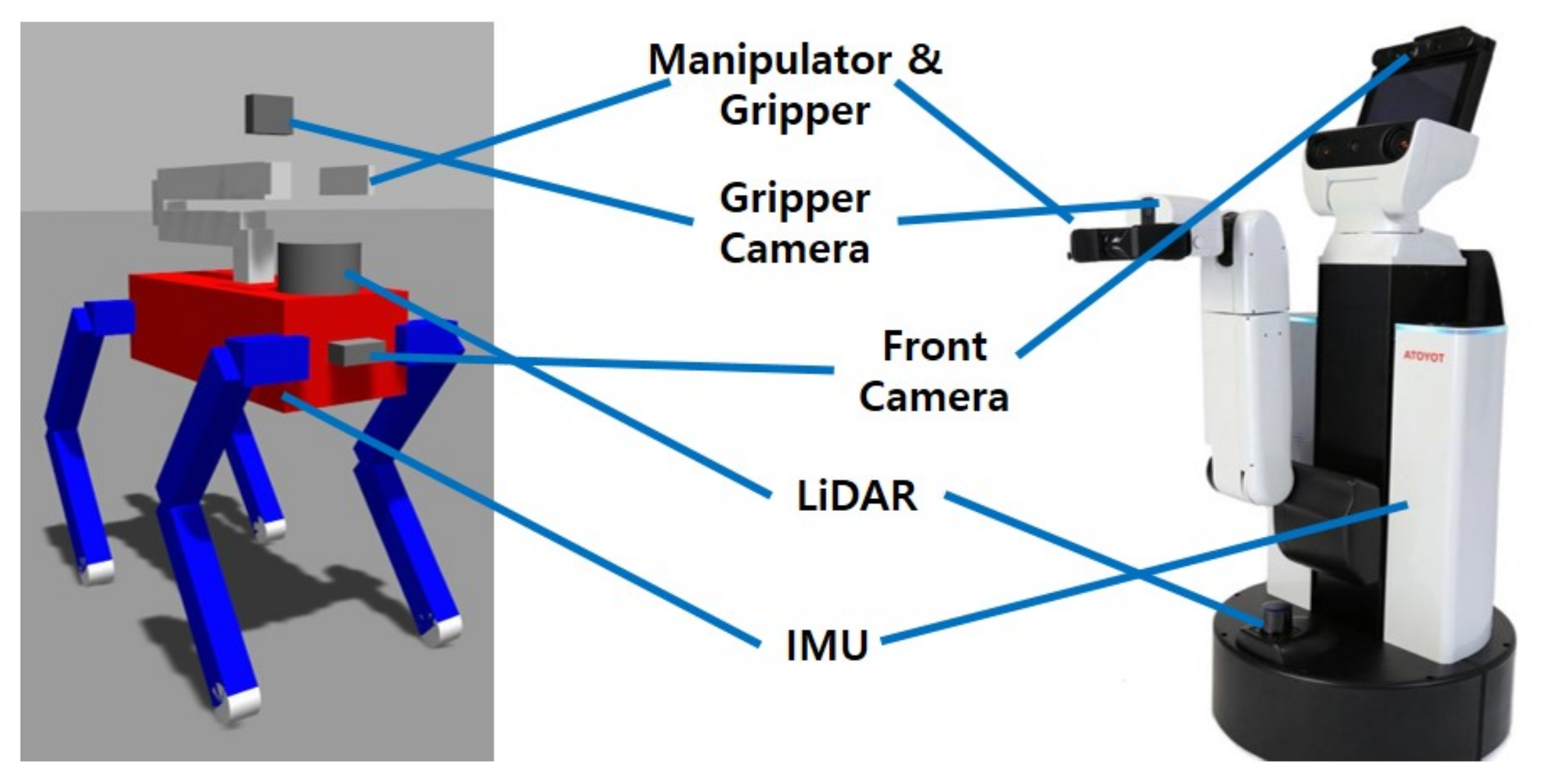
3. System Overview
3.1. Perception
3.2. Behavior Control
3.3. Joint Control
4. Perception
4.1. Per-Object Point Cloud Generation
4.2. Filtering Outliers
4.3. Probing Direction Decision
4.4. Height Map Creation
| Algorithm 1 Height map creation |
|
4.5. Grasp Pose Prediction
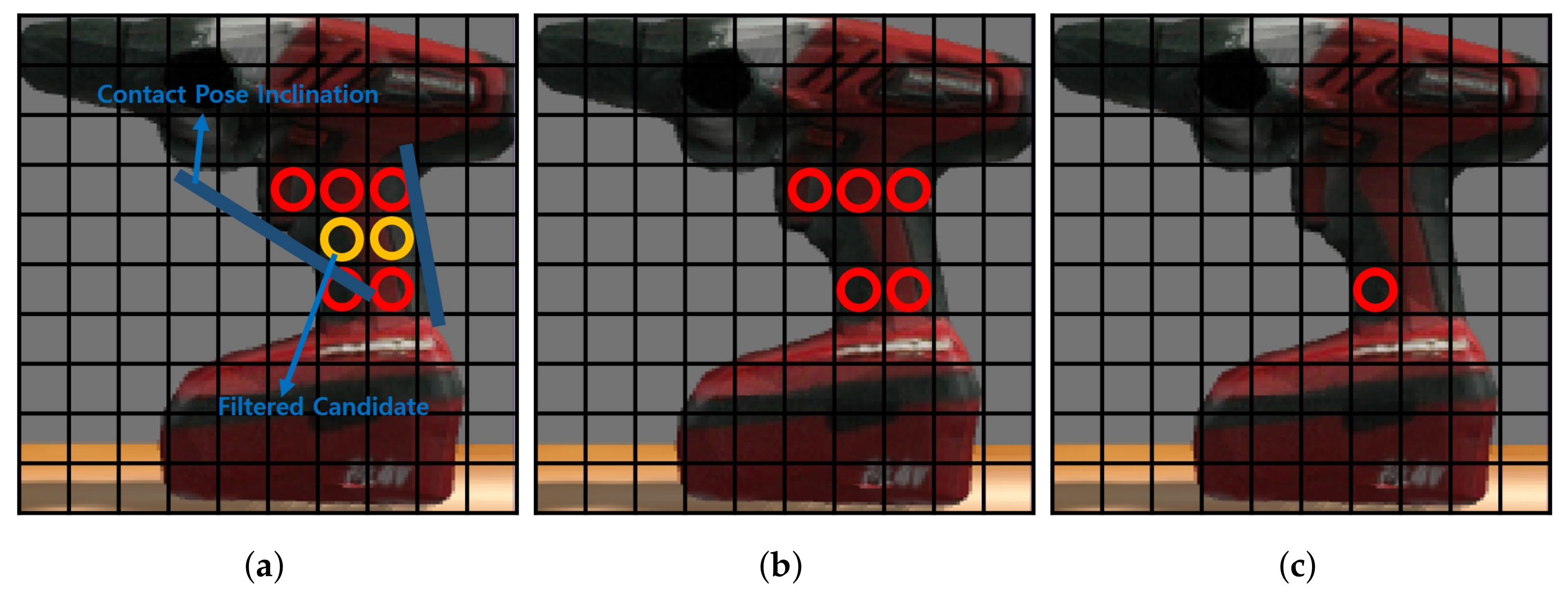
4.5.1. Selecting Grasp Candidates
| Algorithm 2 Selecting grasp candidates |
|
4.5.2. Getting Contact Pose Inclination
| Algorithm 3 Getting contact pose inclination |
|
4.5.3. Selecting Grasp Pose in Height Map
4.5.4. Grasp Pose Transition
| Algorithm 4 Grasp pose transition |
|
4.6. Rotation of an Object on The Floor
5. Behavior Control
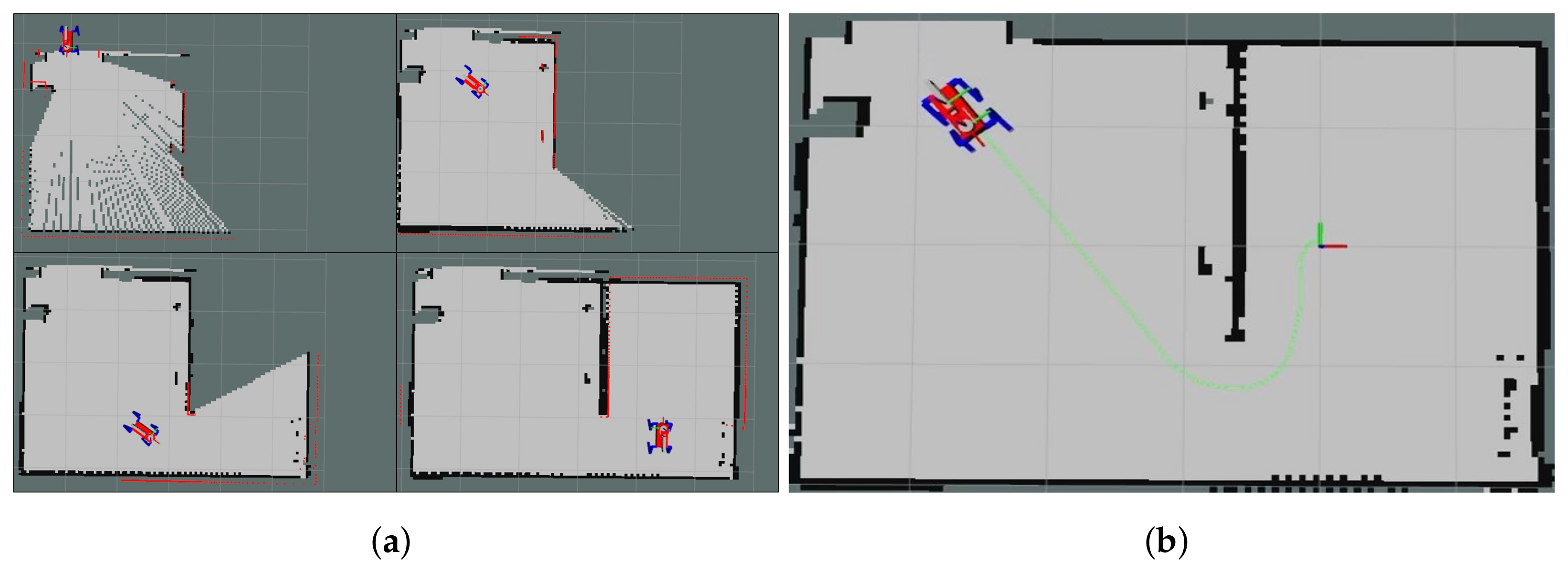
5.1. SLAM
5.2. Navigation
5.3. Approaching
| Algorithm 5 Approaching |
|
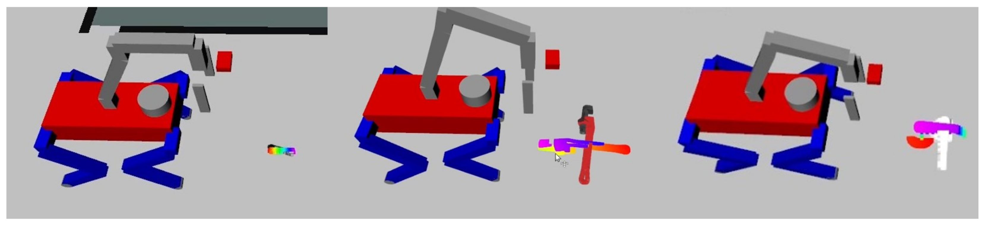
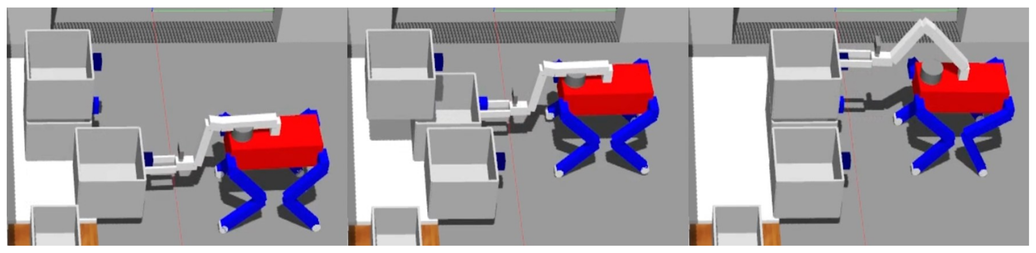
5.4. Grasping an Object
| Algorithm 6 Grasping an object |
|
6. Joint Control
6.1. Manipulator Control
Inverse Kinematics
6.2. Leg Control
6.2.1. COM Controller
6.2.2. Gait
6.2.3. Parameters
6.2.4. Finite State Machine
| Algorithm 7 Finite state machine |
|
6.2.5. Swing Foot Trajectory
| Algorithm 8 Swing foot trajectory |
|
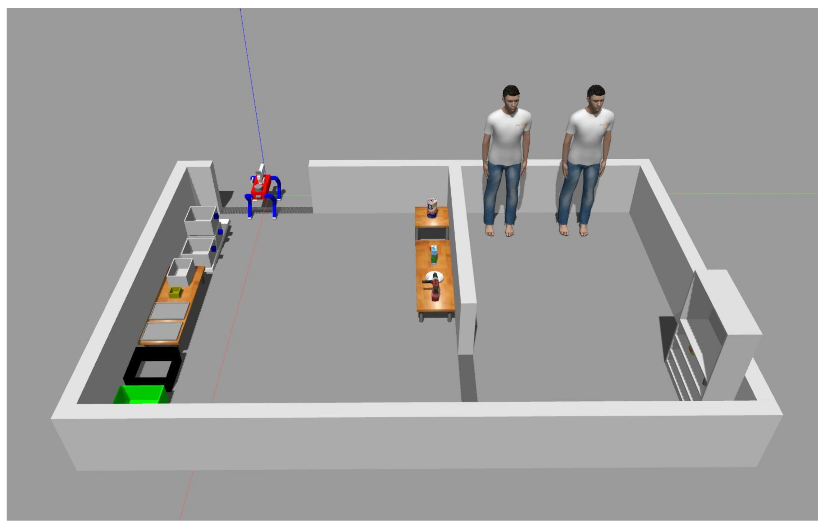
7. Experiment
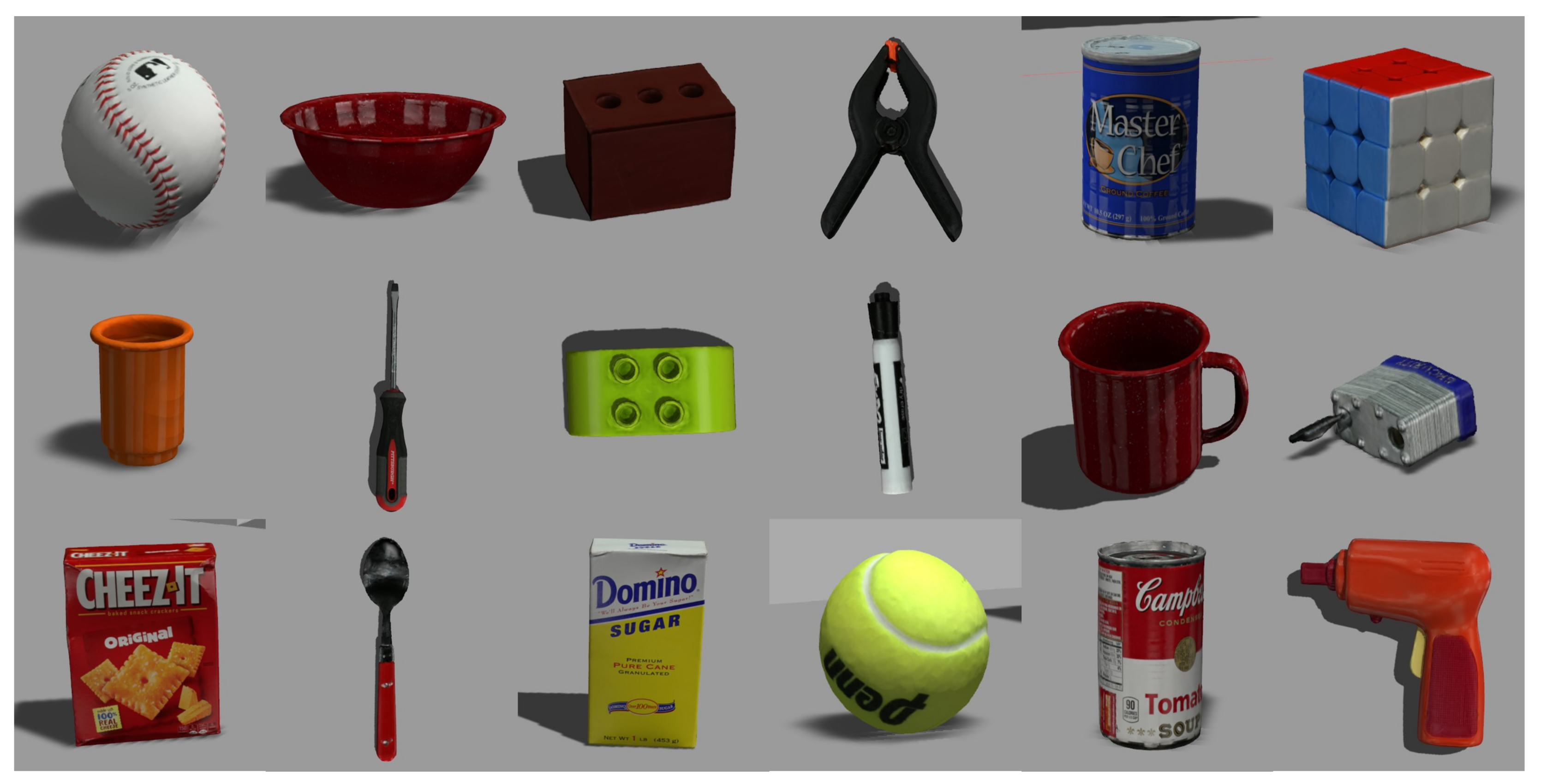
7.1. Objects
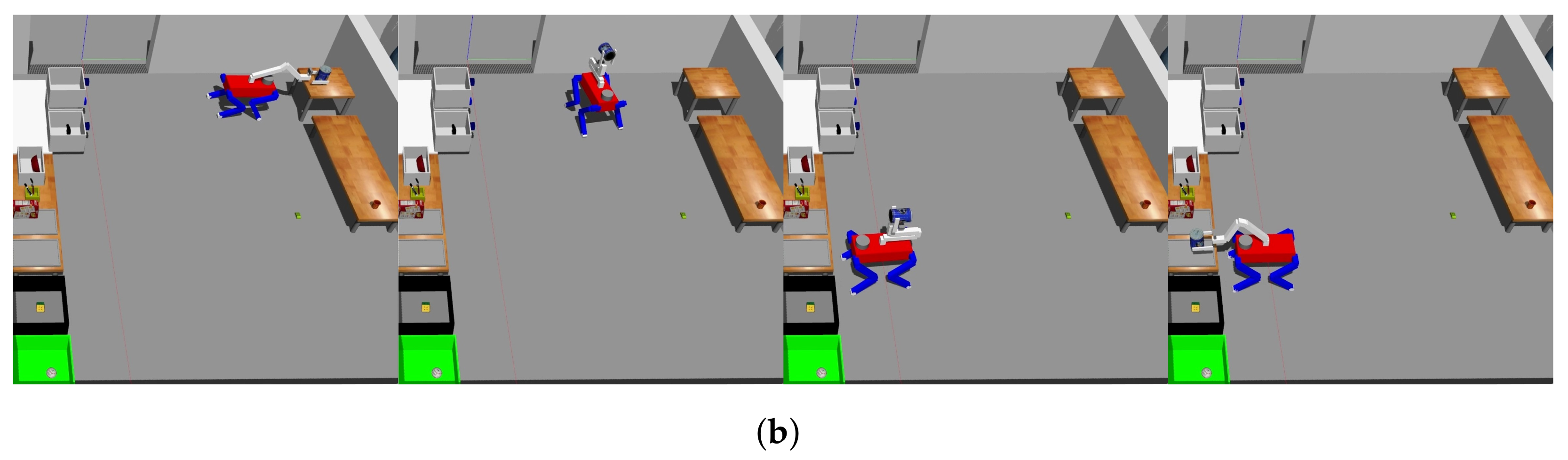
7.2. Tasks
7.3. Results
8. Discussion
9. Conclusions
Author Contributions
Funding
Institutional Review Board Statement
Informed Consent Statement
Data Availability Statement
Conflicts of Interest
Abbreviations
| DOF | Degree of Freedom |
| KNN | K-Nearest Neighbor |
| RANSAC | Random Sample Consensus |
| HSR | Human Support Robot |
| HQP | Hierarchical Quadratic Programming |
| WBC | Whole Body Control |
| PCA | Principal Component Analysis |
| COM | Center of Mass |
| MPC | Model Predictive Control |
| GRF | Ground Reaction Force |
| NLP | Natural Language Processing |
| HRI | Human–Robot Interaction |
References
- Yi, J.B.; Kang, T.; Song, D.; Yi, S.J. Unified Software Platform for Intelligent Home Service Robots. Appl. Sci. 2020, 10, 5874. [Google Scholar] [CrossRef]
- Hansen, S.T.; Hansen, K.D. Public Relation Robots—An Overview; Association for Computing Machinery: New York, NY, USA, 2020; pp. 284–286. [Google Scholar] [CrossRef]
- Daczo, L.D.; Kalova, L.; Bonita, K.L.F.; Lopez, M.D.; Rehm, M. Interaction Initiation with a Museum Guide Robot—From the Lab into the Field; Springer: Berlin/Heidelberg, Germany, 2021; pp. 438–447. [Google Scholar] [CrossRef]
- Duchetto, F.D.; Baxter, P.; Hanheide, M. Lindsey the Tour Guide Robot—Usage Patterns in a Museum Long-Term Deployment. In Proceedings of the 2019 28th IEEE International Conference on Robot and Human Interactive Communication (RO-MAN), New Delhi, India, 14–18 October 2019; pp. 1–8. [Google Scholar] [CrossRef]
- Okano, S.; Matsuhira, N.; Shimokawara, E.; Yamaguchi, T.; Narita, M. Employing Robots in a Museum Environment: Design and Implementation of Collaborative Robot Network. In Proceedings of the 2019 16th International Conference on Ubiquitous Robots (UR), Jeju, Republic of Korea, 24–27 June 2019; pp. 224–227. [Google Scholar] [CrossRef]
- Triebel, R.; Arras, K.; Alami, R.; Beyer, L.; Breuers, S.; Chatila, R.; Chetouani, M.; Cremers, D.; Evers, V.; Fiore, M.; et al. SPENCER: A Socially Aware Service Robot for Passenger Guidance and Help in Busy Airports; Springer: Berlin/Heidelberg, Germany, 2016; Volume 113, pp. 607–622. [Google Scholar] [CrossRef]
- Langedijk, R.M.; Odabasi, C.; Fischer, K.; Graf, B. Studying Drink-Serving Service Robots in the Real World. In Proceedings of the 2020 29th IEEE International Conference on Robot and Human Interactive Communication (RO-MAN), Naples, Italy, 31 August–4 September 2020; pp. 788–793. [Google Scholar] [CrossRef]
- Naik, L.; Palinko, O.; Kollakidou, A.; Bodenhagen, L.; Krüger, N. An interactive drink serving social robot: Initial System Implementation. In Proceedings of the IROS 2020 Workshop: Robots for Health and Elderly Care: An Honest Discourse on the Gap Between Research and Practical Application, Virtual, 29 October 2020. [Google Scholar]
- Chen, C.S.; Lin, C.J.; Lai, C.C. Non-Contact Service Robot Development in Fast-Food Restaurants. IEEE Access 2022, 10, 31466–31479. [Google Scholar] [CrossRef]
- Kang, T.; Song, D.; Yi, J.B.; Kim, J.; Lee, C.Y.; Yoo, Y.; Kim, M.; Jo, H.J.; Zhang, B.T.; Song, J.; et al. Team Tidyboy at the WRS 2020: A modular software framework for home service robots. Adv. Robot. 2022, 36, 836–849. [Google Scholar] [CrossRef]
- Yi, J.B.; Yi, S.J. Mobile Manipulation for the HSR Intelligent Home Service Robot. In Proceedings of the 2019 16th International Conference on Ubiquitous Robots (UR), Jeju, Republic of Korea, 24–27 June 2019; pp. 169–173. [Google Scholar] [CrossRef]
- Kang, T.; Kim, J.; Song, D.; Kim, T.; Yi, S.J. Design and Control of a Service Robot with Modular Cargo Spaces. In Proceedings of the 2021 18th International Conference on Ubiquitous Robots (UR), Gangneung, Republic of Korea, 12–14 July 2021; pp. 595–600. [Google Scholar] [CrossRef]
- Xin, G.; Zeng, F.; Qin, K. Loco-Manipulation Control for Arm-Mounted Quadruped Robots: Dynamic and Kinematic Strategies. Machines 2022, 10, 719. [Google Scholar] [CrossRef]
- Guo, J.; Chai, H.; Li, Y.; Zhang, Q.; Wang, Z.; Zhang, J.; Zhang, Q.; Zhao, H. Research on the Autonomous System of the Quadruped Robot with a Manipulator to Realize Leader-following, Object Recognition, Navigation and Operation. IET Cyber-Syst. Robot. 2022, 4, 376–388. [Google Scholar] [CrossRef]
- Yamamoto, T.; Terada, K.; Ochiai, A.; Saito, F.; Asahara, Y.; Murase, K. Development of Human Support Robot as the research platform of a domestic mobile manipulator. ROBOMECH J. 2019, 6, 1–15. [Google Scholar] [CrossRef]
- Wang, C.Y.; Bochkovskiy, A.; Liao, H.Y.M. YOLOv7: Trainable bag-of-freebies sets new state-of-the-art for real-time object detectors. arXiv 2022, arXiv:2207.02696. [Google Scholar]
- Jin, X.; Han, J. K-Means Clustering. In Encyclopedia of Machine Learning; Sammut, C., Webb, G.I., Eds.; Springer: Boston, MA, USA, 2010; pp. 563–564. [Google Scholar] [CrossRef]
- Fischler, M.A.; Bolles, R.C. Random Sample Consensus: A Paradigm for Model Fitting with Applications to Image Analysis and Automated Cartography. Commun. ACM 1981, 24, 381–395. [Google Scholar] [CrossRef]
- García, C.E.; Prett, D.M.; Morari, M. Model predictive control: Theory and practice—A survey. Automatica 1989, 25, 335–348. [Google Scholar] [CrossRef]
- Ding, Y.; Pandala, A.; Li, C.; Shin, Y.H.; Park, H.W. Representation-Free Model Predictive Control for Dynamic Motions in Quadrupeds. IEEE Trans. Robot. 2020, 37, 1154–1171. [Google Scholar] [CrossRef]
- Di Carlo, J.; Wensing, P.M.; Katz, B.; Bledt, G.; Kim, S. Dynamic Locomotion in the MIT Cheetah 3 Through Convex Model-Predictive Control. In Proceedings of the 2018 IEEE/RSJ International Conference on Intelligent Robots and Systems (IROS), Detroit, MI, USA, 1–5 October 2018; pp. 1–9. [Google Scholar] [CrossRef]
- Ding, Y.; Pandala, A.; Park, H.W. Real-time Model Predictive Control for Versatile Dynamic Motions in Quadrupedal Robots. In Proceedings of the 2019 International Conference on Robotics and Automation (ICRA), Montreal, QC, Canada, 20–24 May 2019; pp. 8484–8490. [Google Scholar] [CrossRef]
- Escande, A.; Mansard, N.; Wieber, P.B. Hierarchical quadratic programming: Fast online humanoid-robot motion generation. Int. J. Robot. Res. 2014, 33, 1006–1028. [Google Scholar] [CrossRef]
- Yi, J.B.; Kim, J.; Kang, T.; Song, D.; Park, J.; Yi, S.J. Anthropomorphic Grasping of Complex-Shaped Objects Using Imitation Learning. Appl. Sci. 2022, 12, 12861. [Google Scholar] [CrossRef]
- Lei, Q.; Chen, G.Y.; Wisse, M. Fast grasping of unknown objects using principal component analysis. AIP Adv. 2017, 7, 095126. [Google Scholar]
- Lei, Q.; Chen, G.Y.; Meijer, J.; Wisse, M. A novel algorithm for fast grasping of unknown objects using C-shape configuration. AIP Adv. 2018, 8, 025006. [Google Scholar]
- Mishra, S.; Sarkar, U.; Taraphder, S.; Datta, S.; Swain, D.; Saikhom, R.; Panda, S.; Laishram, M. Principal Component Analysis. Int. J. Livest. Res. 2017, 7, 60–78. [Google Scholar] [CrossRef]
- Quigley, M.; Conley, K.; Gerkey, B.; Faust, J.; Foote, T.; Leibs, J.; Wheeler, R.; Ng, A. ROS: An open-source Robot Operating System. In Proceedings of the ICRA Workshop on Open Source Software, Kobe, Japan, 12–17 May 2009; Volume 3. [Google Scholar]
- Lin, K.Y.; Tseng, Y.H.; Chiang, K.W. Interpretation and Transformation of Intrinsic Camera Parameters Used in Photogrammetry and Computer Vision. Sensors 2022, 22, 9602. [Google Scholar] [CrossRef]
- Koenig, N.; Howard, A. Design and use paradigms for Gazebo, an open-source multi-robot simulator. In Proceedings of the 2004 IEEE/RSJ International Conference on Intelligent Robots and Systems (IROS), Sendai, Japan, 28 September–2 October 2004; Volume 3, pp. 2149–2154. [Google Scholar] [CrossRef]
- Kim, J.; Kang, T.; Song, D.; Yi, S.J. PAWDQ: A 3D Printed, Open Source, Low Cost Dynamic Quadruped. In Proceedings of the 2021 18th International Conference on Ubiquitous Robots (UR), Gangneung, Republic of Korea, 12–14 July 2021; pp. 217–222. [Google Scholar] [CrossRef]


| Body Length | Body Width | Thigh Length | Calf Length |
|---|---|---|---|
| 0.419 m | 0.2505 m | 0.22 m | 0.22 m |
| 0.06 m | 0.25 m | 0.06 m | 0.21 m | 0.1 m |
| Parameter | Value |
|---|---|
| [0.1 0 0; 0 0.1 0; 0 0 0.1] | |
| [100,000 0 0; 0 150,000 0; 0 0 100,000] | |
| [100 0 0; 0 100 0; 0 0 100] | |
| [5000 0 0; 0 5000 0; 0 0 5000] | |
| [2 0 0; 0 4 0; 0 0 3] | |
| 6 | |
| 0.3 | |
| 0.1 | |
| 0.03 |
| Trial | Objects | Success Num | Failure Num | Success Rate | Time |
|---|---|---|---|---|---|
| 1 | Rubik’s cube, clamp, marker, cracker, spoon, Lego, coffee can, baseball, bowl, cup | 10 | 0 | 100% | 19:07 |
| 2 | tennis ball, bowl, driver, padlock, spoon, sugar, tomato soup, toy gun, mug, brick | 8 | 2 | 80% | 18:55 |
| 3 | tennis ball, mug, driver, toy gun, padlock, coffee can, Rubik’s cube, tomato soup, bowl, brick | 10 | 0 | 100% | 20:48 |
| 4 | tennis ball, bowl, padlock, Lego, marker, cracker, brick, mug, tomato soup, Rubik’s cube | 10 | 0 | 100% | 19:59 |
| 5 | marker, mug, tomato soup, Rubik’s cube, clamp, driver, cup, bowl, coffee can, baseball | 10 | 0 | 100% | 18:10 |
| Average | 9.6 | 0.4 | 96% | 19:24 |
Disclaimer/Publisher’s Note: The statements, opinions and data contained in all publications are solely those of the individual author(s) and contributor(s) and not of MDPI and/or the editor(s). MDPI and/or the editor(s) disclaim responsibility for any injury to people or property resulting from any ideas, methods, instructions or products referred to in the content. |
© 2023 by the authors. Licensee MDPI, Basel, Switzerland. This article is an open access article distributed under the terms and conditions of the Creative Commons Attribution (CC BY) license (https://creativecommons.org/licenses/by/4.0/).
Share and Cite
Yi, J.-B.; Nasrat, S.; Jo, M.-s.; Yi, S.-J. A Software Platform for Quadruped Robots with Advanced Manipulation Capabilities. Sensors 2023, 23, 8247. https://doi.org/10.3390/s23198247
Yi J-B, Nasrat S, Jo M-s, Yi S-J. A Software Platform for Quadruped Robots with Advanced Manipulation Capabilities. Sensors. 2023; 23(19):8247. https://doi.org/10.3390/s23198247
Chicago/Turabian StyleYi, Jae-Bong, Shady Nasrat, Min-seong Jo, and Seung-Joon Yi. 2023. "A Software Platform for Quadruped Robots with Advanced Manipulation Capabilities" Sensors 23, no. 19: 8247. https://doi.org/10.3390/s23198247
APA StyleYi, J.-B., Nasrat, S., Jo, M.-s., & Yi, S.-J. (2023). A Software Platform for Quadruped Robots with Advanced Manipulation Capabilities. Sensors, 23(19), 8247. https://doi.org/10.3390/s23198247