Abstract
Camera attitude control systems for robots require a compact structure and high responsiveness. However, due to the combination structure of several actuators, the camera attitude control system is large. To address this issue, this study proposes a three-degree-of-freedom (3DOF) voice coil actuator. A single actuator is used to generate 3DOF motion, which is driven by a four-phase current. This study also describes the basic structure and operating principle of the actuator and clarifies the torque characteristics using a three-dimensional (3D) finite element method (FEM). Furthermore, the dynamic modeling and control methods are presented. The FEM and dynamic simulation results reveal that the proposed actuator can be arbitrarily driven in 3DOF.
1. Introduction
Surrounding recognition is important for autonomous mobile systems such as robots, drones, and self-driving cars [1,2,3]. These systems gather visual information using a camera in an unknown environment, necessitating a high level of spatial awareness. However, image deterioration occurs due to its vibration. Furthermore, the size increases due to a multiple-degree-of-freedom (DOF) mechanism for changing the camera attitude. Various parallel link mechanisms have been developed to generate the multiple-DOF motion [4,5,6,7]; however, the mechanisms have some disadvantages, such as a large number of components, structural complexity, and narrow driving angle. To solve these problems, this study focuses on multiple-DOF actuators. They can generate multiple-DOF motions with a single actuator.
Various types of multiple-DOF actuators have been proposed: synchronous [8,9,10], stepping [11,12], and induction motor types [13]. However, these conventional actuators require a control device and structure of a large size to achieve a high torque density and continuous rotation. In the driving source for the camera attitude control system, a compact structure with a few components and high responsiveness is required. Moreover, it must be able to be driven using a simple control device. Thus, this study proposed a novel three-DOF voice coil actuator (3DOFVCA) driven by only a four-phase current, with the minimum possible configuration [14].
This study describes the structure, operating principle, and dynamics of the proposed 3DOFVCA. The torque characteristics are investigated using a three-dimensional finite element method (3D FEM). The FEM analysis results show that the 3DOFVCA can generate torque on the three-axis. Furthermore, the dynamic modeling and control methods are presented. The dynamic simulation results clarify that the proposed actuator can be controlled in 3DOF.
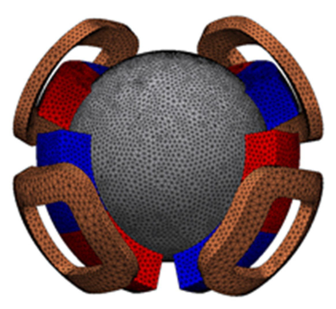
2. Three-Degree-of-Freedom Voice Coil Actuator
2.1. Basic Structure
Figure 1 and Figure 2 show the overview and side views of the proposed 3DOFVCA, respectively. Four coils and permanent magnets (PMs) tilted 45° were arranged at an interval of 90°. The PMs were arranged with alternating positive and negative 45° inclinations. This actuator includes a moving coil structure with four coils. The coils were coupled at a neutral point, and a spherical bearing mechanically supported the rotor. The stator was made up of spherical PMs and outer and inner yokes. The actuator is a surface permanent magnet structure and has no salient pole. The magnetic circuit is independent and symmetric for each of the four PMs. The proposed actuator can generate 3DOF motion by only one rotor with four coils, four magnets, two yokes, and one spherical bearing. Therefore, the advantage of the actuator is the integration of electromagnetic force generation mechanisms within a spherical volume.
Figure 1.
The 3DOFVCA driven by four-phase current: (a) entire view; (b) stator; (c) rotor; and (d) motion of the rotor. The half of the outer stator yoke and rotating coil support are translucent for visibility.
Figure 2.
Side view of the 3DOFVCA when the rotor position is the origin.
The model was designed for principle verification. The outer diameter of the stator was 30 mm, and the number of turns was 40. Figure 3 and Table 1 show the detailed design parameters and the parameter values, respectively.
Figure 3.
Design parameters.
Table 1.
Design parameter values.
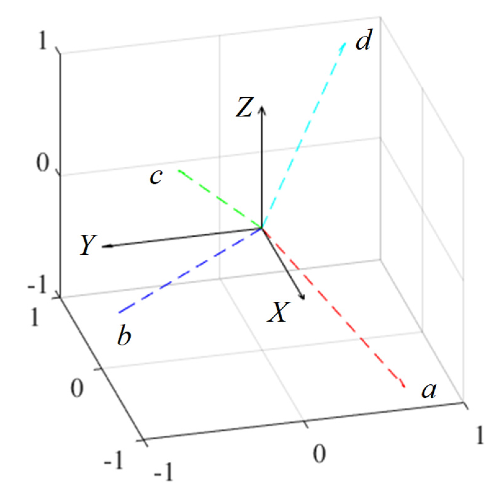
2.2. Operating Principle
A magnetic attraction force was generated using one exciting coil, as shown in Figure 2. The 3DOF motion was achieved by adjusting the current direction in each coil (see Figure 4). Table 2 presents the torque generation patterns. The currents in each phase were applied in an equilibrium state of the current in an electric circuit. This means that the sum of the currents in each phase is zero at the neutral point. Due to its structural and magnetic symmetry, this current equilibrium condition is also established during rotation. This is because the magnetized direction of the PM alternates between N and S poles when viewed circumferentially. Therefore, the actuator was driven by a four-phase half-bridge circuit. The torque is generated because the flux linkage is changed by rotation.
Figure 4.
Operating principle of the 3DOFVCA: (a) X-axis; (b) Y-axis; and (c) Z-axis.
Table 2.
Current pattern for the torque generation.
3. Torque Characteristics
The torque characteristics of the proposed 3DOFVCA were investigated by employing the 3D FEM through a magnetic field analysis using a T-ω method (MAGNET, Siemens) [15,16]. The analysis validity was confirmed in reference [17] (see Appendix A). The analysis conditions and results of the basic model are shown, and the PM arrangement’s structural comparison is presented.
3.1. Analysis Conditions
Figure 5 shows the 3D mesh model of the basic model, excluding air. The number of elements was approximately 2,360,000. The residual magnetic flux density of the PM was 1.3 T, and the coercive force was 1.05 × 10⁶ A/m. The yokes were made of electromagnetic soft iron (SUY). The limit in the current was a current density of 20 A/mm2.
Figure 5.
Three-dimensional mesh model excluding the air region and outer stator yoke.
3.2. Results
Figure 6 shows the magnetic flux density distribution. It was confirmed that the magnetic circuit between the PM and yokes is symmetric. The torque characteristics were calculated when a current was applied to generate the torque around each axis. Only the torque around the driving axis is generated, as shown in Figure 7. The torque fluctuation during rotation is caused by the approach of the pole center of the coils and PMs. The facing area between the coil and PM is small in rotation around the Z-axis compared to the rotation around the X- and Y-axis. Therefore, the driving range around the Z-axis is narrow.
Figure 6.
Magnetic flux density distribution of the 3DOFVCA: (a) whole view and (b) without outer yoke and coils.
Figure 7.
Analysis results of the static torque: (a) rotation around the X-axis; (b) rotation around the Y-axis; and (c) rotation around the Z-axis.
3.3. Structural Comparison
The effect of the changing PM placement angle is verified as shown in Figure 8 and Figure 9, which present the analyzed results. The torque around the X- and Y-axis becomes larger by increasing the placement angle. However, the torque around the Z-axis becomes smaller. This is because the force vector direction in each coil changes. The driving range around the X- and Y-axis expands, whereas that of the Z-axis narrows. The torque can be distributed for each axis by adjusting the PM placement angle, although there is a trade-off in the maximum torque and driving range. Thus, it is necessary to design according to the application.
Figure 8.
Placement angle of the PM: (a) 30°; (b) 45°; and (c) 60°.

Figure 9.
Torque characteristics when the placement angles of the PMs are changed: (a) rotation around the X-axis; (b) rotation around the Y-axis; and (c) rotation around the Z-axis.
4. Modeling and Control Method
This section describes the dynamic modeling and control method. The dynamics of the proposed 3DOFVCA are expressed as electrical and mechanical responses. Furthermore, the circuit and motion equations are derived. The control method for controlling 3DOF motion by a four-phase current is presented.
4.1. Dynamic Modeling
First, the electrical dynamics was considered. The circuit equation is as follows:
where v is the voltage, I is the current, R is the coil’s resistance, L is the self-inductance, M is the mutual inductance, and e is the back-EMF. In this actuator, the inductance can be regarded as constant because of the narrow rotational range. From the symmetry of the magnetic circuit, the mutual inductances can be considered the same:
In the equilibrium state of the current, the following terms are given:
From Equations (2)–(5), the circuit equation can be converted as follows:
where ρ = d/dt and L = Laa – M. Next, the conversion between the electrical and mechanical energies is expressed as follows:
where τ is the torque and KT is the torque constant. The torque constant was changed by the rotation. Therefore, the coil position vectors in each phase are defined using φ and ψ, where φ is the longitude of the coil position vector and ψ is the latitude. The torque was calculated as the total torque in each coil. For example, Figure 10 shows the torque constant maps of the a-phase. The attitude is expressed by the XYZ-Euler angle (α, β, γ). The rotation matrix is given as follows:
where c and s represent cosine and sine, respectively.
Figure 10.
Torque constant map in a-phase: (a) rotation around the X-axis; (b) rotation around the Y-axis; and (c) rotation around the Z-axis.
The mechanical dynamics was obtained using the Lagrange equation of motion as follows:
where q is the generalized coordinate, and Lq is the Lagrangian. Lq is defined as follows:
where K is the kinetic energy and P is the potential energy. K is defined as follows:
where ω is the angular velocity and I is the tensor of inertia. ω is defined as follows:
I is defined as follows:
The potential energy was assumed to be zero because the center mass of the rotor was located at the origin.
where q = [α β γ]T, I1 = Ixx = Iyy, and I3 = Izz. From Equations (6), (7) and (15), Figure 11 shows the 3DOFVCA model. In this model, the input was the voltage, and the output was the attitude. The torque constant was obtained from the results of the 3D FEM analysis. The back-EMF constant was assumed to be the same as the torque constant.
Figure 11.
Block diagram of the 3DOFVCA.
4.2. Control Method
The coordinate transformation between a–b–c–d and α–β–γ coordinates are required to control the attitude of the actuator. Figure 12 shows the generated force vectors in each coil. The coordinate transformation matrix can be expressed as follows:
where f is the physical quantity such as a voltage and current. The inverse transformation can be expressed as follows:
where T+ is the pseudoinverse matrix. Figure 13 shows the attitude control system. A feedback control system using a PID controller can be used to control the attitude.
Figure 12.
Coordinate system with the generated force vector.
Figure 13.
Attitude control system.
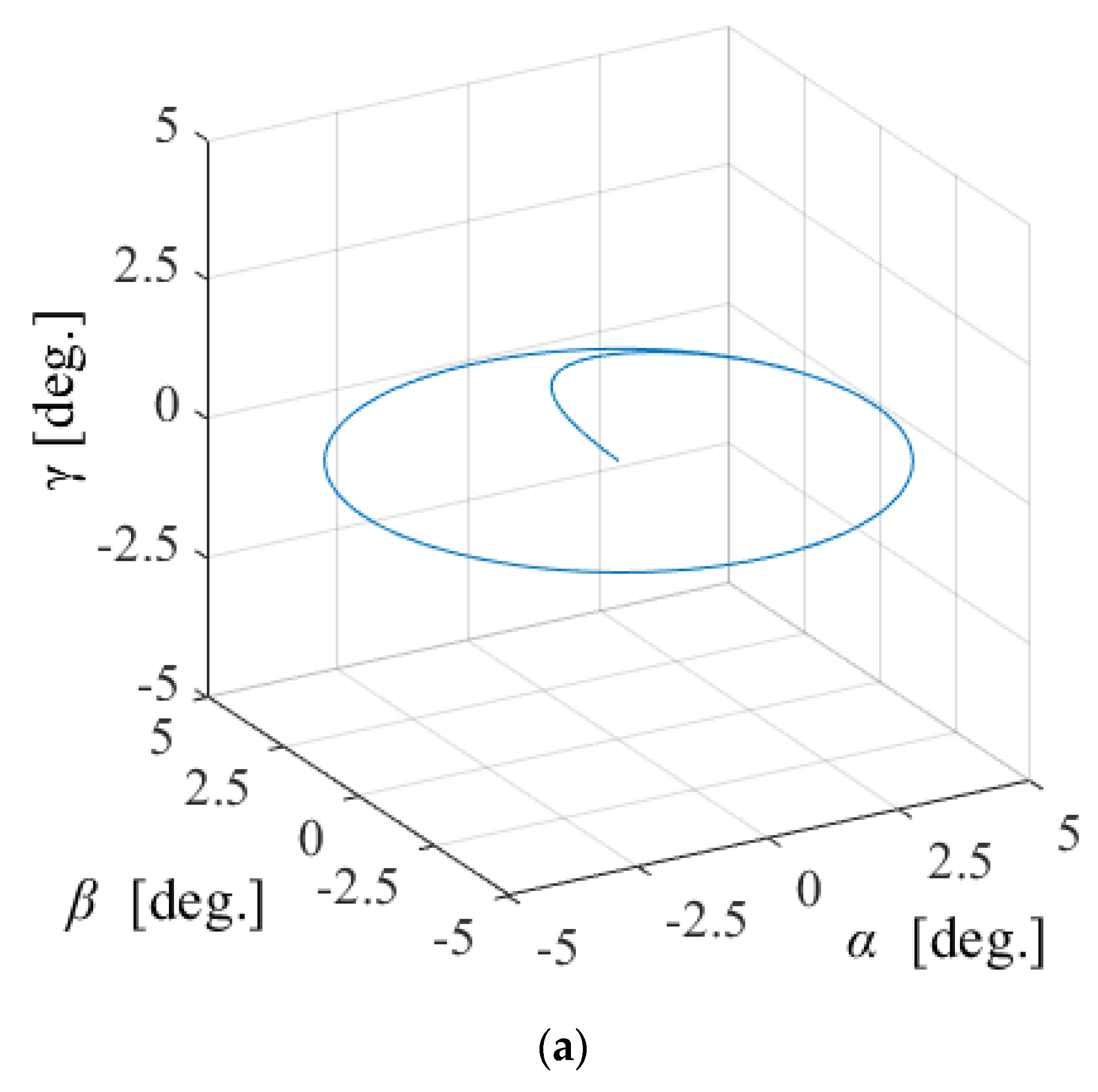
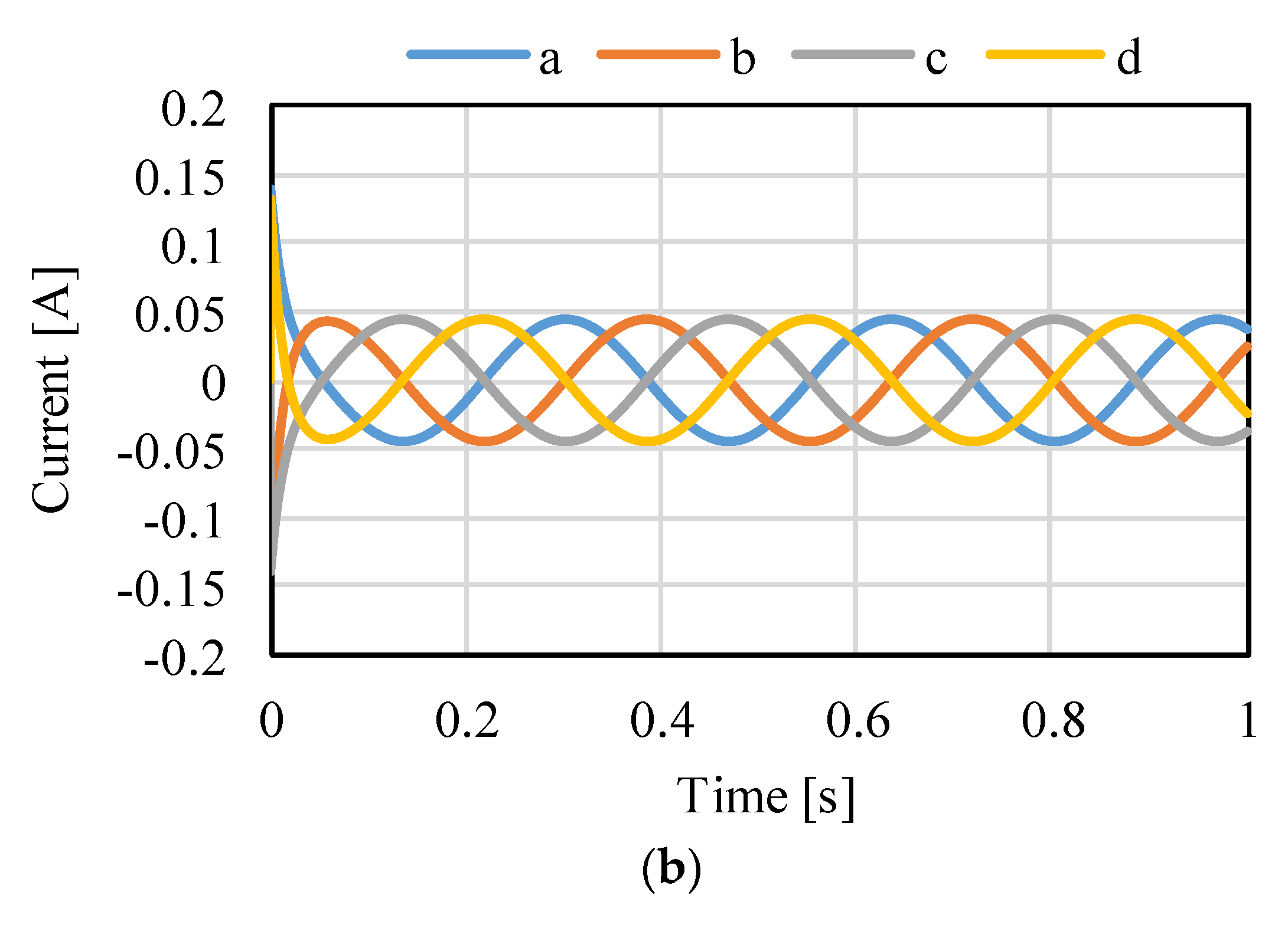
5. Dynamic Simulation
A dynamic simulation was conducted to verify the effectiveness of the control method. The time step for the simulation was set to 0.1 ms because the results did not change when the shorter time step was set. Table 3 presents the actuator parameters. The gain kp, ki, and kd were 1, 0.1, and 0.001, respectively. These values were designed by trial and error. The gains were set for stable convergence without overshoot and steady-state deviation. The time response of the system was calculated using the circuit equation Equation (1), torque generation equation Equation (7), and motion equation Equation (15). The variation of the torque constant and back-EMF constant were calculated as Lookup tables obtained through 3D FEM analysis. In addition, Simulink was used for a numerical calculation using a Runge–Kutta solver.
Table 3.
Actuator parameter values.
Figure 14, Figure 15 and Figure 16 shows the control results for α-, β-, and γ-rotation. The target values were 5° in each simulation. The rotor was set to the target attitude, and there was a response delay in the transient state. The steady-state deviations were negligible in each direction. Figure 17 shows the results of the circular motion tracking. The rotor rotates along a circle, and the total currents between each phase are zero. Therefore, the equilibrium state was obtained. From these results, the actuator can be controlled using the proposed method. In this study, the target accuracy was set at 0.1° or less. In the actual system, friction compensation and identification are important because the accuracy decreases due to friction.

Figure 14.
Calculated results when the target is the rotation in α: (a) attitude and (b) current.
Figure 15.
Calculated results when the target is the rotation in β: (a) attitude and (b) current.
Figure 16.
Calculated results when the target is the rotation in γ: (a) attitude and (b) current.

Figure 17.
Circular motion in α-β: (a) attitude and (b) current.
In an actual system, the dimensional specifications and actuator parameters may be slightly different. First, it is described when the dimensional parameters listed in Table 1 are different between the analysis and experiment due to the machining and assembly errors. The outer and inner yoke’s dimensional error changes the air gap length. When the gap increases due to the errors, the torque decreases by reduction of the magnetic resistance. However, the yoke made by a soft magnetic material has a smaller dimensional error than a permanent magnet, so the effect is small. On the other hand, a permanent magnet has a larger dimensional error than yokes. Therefore, the torque differs slightly between experiment and analysis due to minute changes in size; however, the proposed control method is effective in this case as well. As for the coil dimensions, if the coil can be manufactured with the designed number of turns, the effect on the torque is small. To increase the torque density, the winding space factor must be improved to increase the magnetomotive force. Next, the parameter change listed in Table 3 is described. The inertia error affects the mechanical responsiveness; however, the effect is small because the machining error is small. The change of coil resistance and inductance affects the electrical responsiveness. The viscous friction coefficient determines the damping characteristics and affects acceleration performance.
6. Conclusions
This study proposed a novel 3DOFVCA driven by a four-phase current. The torque characteristics were clarified by employing the 3D FEM. The results showed that the actuator can generate the torque on the three-axis in the rotational range of ±20°. The actuator is 30 mm in diameter and generated a maximum torque of about 7 mNm. The limitation of this actuator is that it cannot rotate infinitely. A dynamic modeling method was proposed using the circuit, energy conversion, and motion equations. The dynamic simulation results confirmed the validity of the proposed attitude control method using the coordinate transformation between the four-phase voltage and Euler angle.
Author Contributions
Funding acquisition, A.H.; Investigation, A.H.; Methodology, A.H.; Project administration, K.H.; Validation, A.H.; Writing—original draft, A.H. All authors have read and agreed to the published version of the manuscript.
Funding
This work was supported by the JSPS Grant-in-Aid for Research Activity Start-up (grant number: 21K20404).
Conflicts of Interest
The authors declare no conflict of interest.
Appendix A
In this study, a 3D FEM analysis software (MAGNET, Siemens) was used to evaluate the torque characteristics of a proposed actuator. In [17], the qualitative validity of the analysis was clarified by comparison of analysis and experiment, as shown in Figure A1.

Figure A1.
Validity of torque analysis: (a) X-axis and (b) Z-axis.
References
- Kurazume, R.; Hirose, S. Development of image stabilization for remote operation of walking robots. In Proceedings of the IEEE International Conference on Robotics and Automation, San Francisco, CA, USA, 24–28 April 2000; pp. 1856–1861. [Google Scholar]
- Hsu, S.-C.; Liang, S.-F.; Fan, K.-W.; Lin, C.-T. A Robust In-Car Digital Image Stabilization Technique. IEEE Trans. Syst. Man Cybern. C 2007, 37, 234–247. [Google Scholar]
- Anguilar, W.G.; Angulo, C. Real-time video stabilization without phantom movements for micro aerial vehicles. EURASIP J. Image Video Process. 2014, 2014, 46. [Google Scholar] [CrossRef]
- Behi, F. Kinematic analysis for a six-degree-of-freedom 3-PRPS parallel mechanism. IEEE J. Robot. Automat. 1988, 4, 561–565. [Google Scholar] [CrossRef]
- Geng, Z.; Haynes, L.S. Six-degree-of-freedom active vibration isolation using a stewart platform mechanism. J. Robot. Syst. 1993, 10, 725–744. [Google Scholar] [CrossRef]
- Abeywardena, S.; Chen, C. Inverse dynamic modelling of a three-legged six-degree-of-freedom parallel mechanism. Multibody Syst. Dyn. 2017, 41, 1–24. [Google Scholar] [CrossRef]
- Moldvan, L.; Gligor, A.; Grif, H.-S.; Moldvan, F. Dynamic Numerical Simulation of the 6-PGK Parallel Robot Manipulator. Proc. Rom. Acad. Ser. A 2019, 20, 67–75. [Google Scholar]
- Kahlen, K.; Voss, I.; Priebe, C.; Doncker, R.D. Torque Control of a Spherical Machine With Variable Pole Pitch. IEEE Trans. Power Electron. 2004, 19, 1628–1634. [Google Scholar] [CrossRef]
- Wang, W.; Wang, J.; Jewel, G.W.; Howe, D. Design and Control of a Novel Spherical Permanent Magnet Actuator with Three Degrees of Freedom. IEEE/ASME Trans. Mechatron. 2003, 8, 457–468. [Google Scholar] [CrossRef]
- Nishiura, Y.; Hirata, K.; Sakaidani, Y. 3-DOF Outer Rotor Electromagnetic Spherical Actuator. Int. J. Auto. Tech. 2016, 10, 591–598. [Google Scholar] [CrossRef]
- Chirikijian, G.S.; Stein, D. Kinematic Design and Commutation of a Spherical Stepper Motor. IEEE/ASME Trans. Mechatron. 1999, 4, 342–353. [Google Scholar] [CrossRef]
- Kasashima, N.; Ashida, K.; Yano, T.; Gofuku, A.; Shibata, M. Torque Control Method of an Electromagnetic Spherical Motor Using Torque Map. IEEE/ASME Trans. Mechatron. 2016, 21, 2050–2060. [Google Scholar] [CrossRef]
- Kumagai, M.; Hollis, R.L. Development and Control of a Three DOF Spherical Induction Motor. In Proceedings of the IEEE International Conference on Robotics and Automation, Karlsruhe, Germany, 6–10 May 2013; pp. 1528–1533. [Google Scholar]
- Heya, A.; Hirata, K. Proposal of Novel Multiple-Degree-of-Freedom Voice Coil Actuator. In Proceedings of the IEEE International Magnetics Conference, Lyon, France, 26–30 April 2021; p. BD-09. [Google Scholar]
- Webb, J.P.; Forghani, B. A T-Ω method using hierarchal edge elements. IEE Proc. Sci. Meas. Tech. 1995, 142, 133–141. [Google Scholar] [CrossRef]
- Webb, J.P.; Forghani, B. DC Current Distributions and Magnetic Fields using the T-Ω Edge-Element Method. IEEE Trans. Magn. 1995, 31, 1444–1447. [Google Scholar] [CrossRef]
- Heya, A.; Hirata, K. Experimental Verification of Three-Degree-of-Freedom Electromagnetic Actuator for Image Stabilization. Sensors 2020, 20, 2485. [Google Scholar] [CrossRef] [PubMed]
Publisher’s Note: MDPI stays neutral with regard to jurisdictional claims in published maps and institutional affiliations. |
© 2022 by the authors. Licensee MDPI, Basel, Switzerland. This article is an open access article distributed under the terms and conditions of the Creative Commons Attribution (CC BY) license (https://creativecommons.org/licenses/by/4.0/).