

Vulnerabilities of the Open Platform Communication Unified Architecture Protocol in Industrial Internet of Things Operation


Abstract
:1. Introduction
1.1. Background and Motivation
1.2. Problem Setup
1.3. Goal and Purpose
- We propose a framework for discovering vulnerabilities and creating countermeasures for analysis targets.
- We selected the OPC UA as an analysis target and applied it to the framework through a case study to derive results.
- We analyzed the attack scenario from the attacker’s viewpoint to identify the attack path and create countermeasures.
2. Related Work
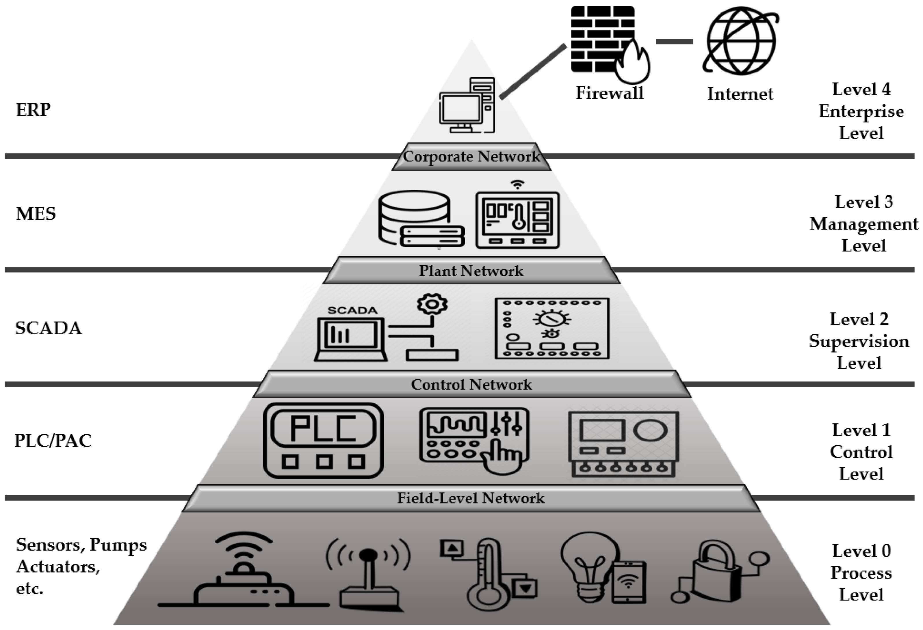
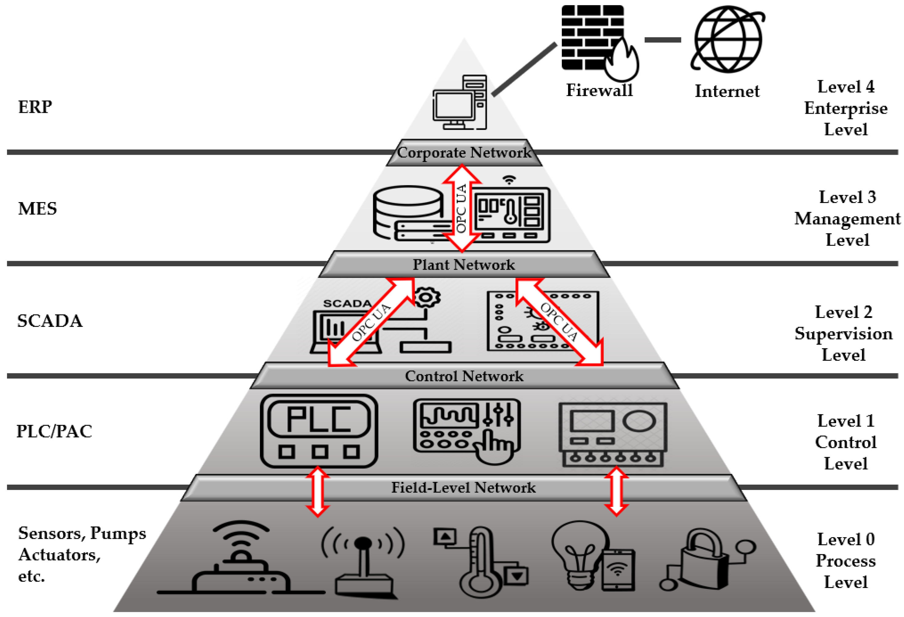
2.1. Trends in Protocols for Industrial Control
2.2. OPC Protocol
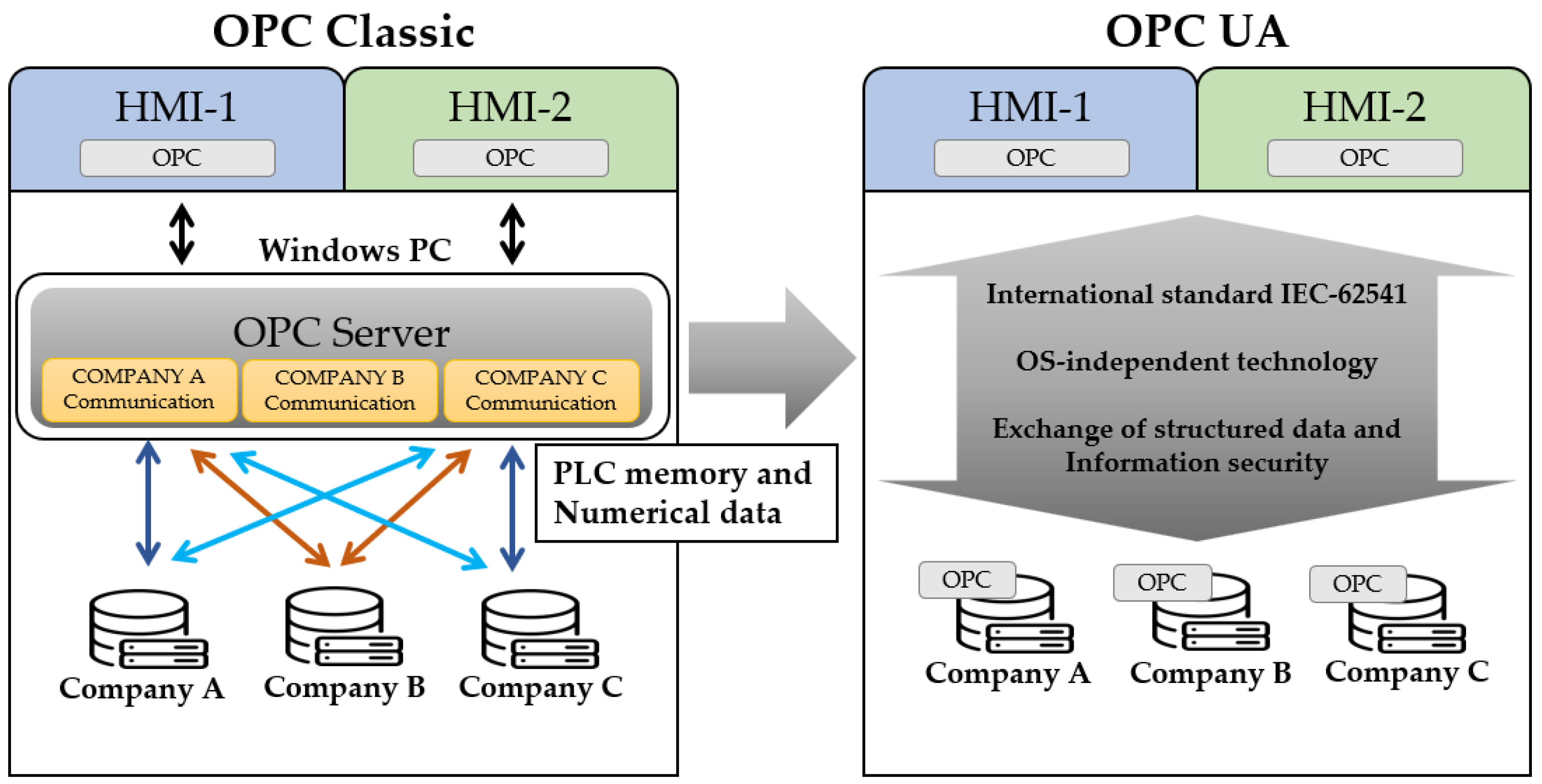
2.2.1. OPC Classic
2.2.2. OPC UA
- Operation on Windows PC and various automation devices;
- Exchange of structured data, semantic information, simple numerical values, and memory data;
- Enhanced security.
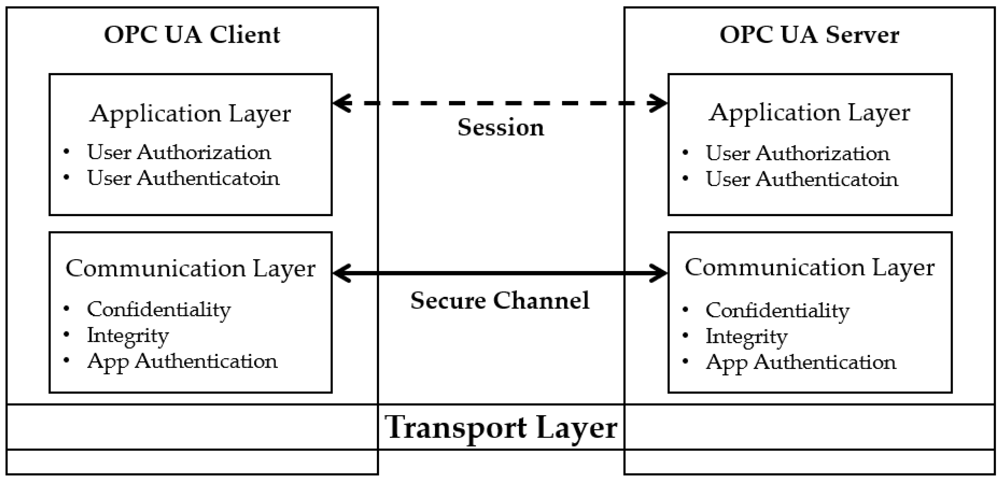
2.2.3. OPC UA Security Model
2.3. OPC UA Security Analysis
2.4. Threat Modeling
- STRIDE
- 2.
- PASTA
- 3.
- OCTAVE
- 4.
- Trike
- 5.
- LINDDUN
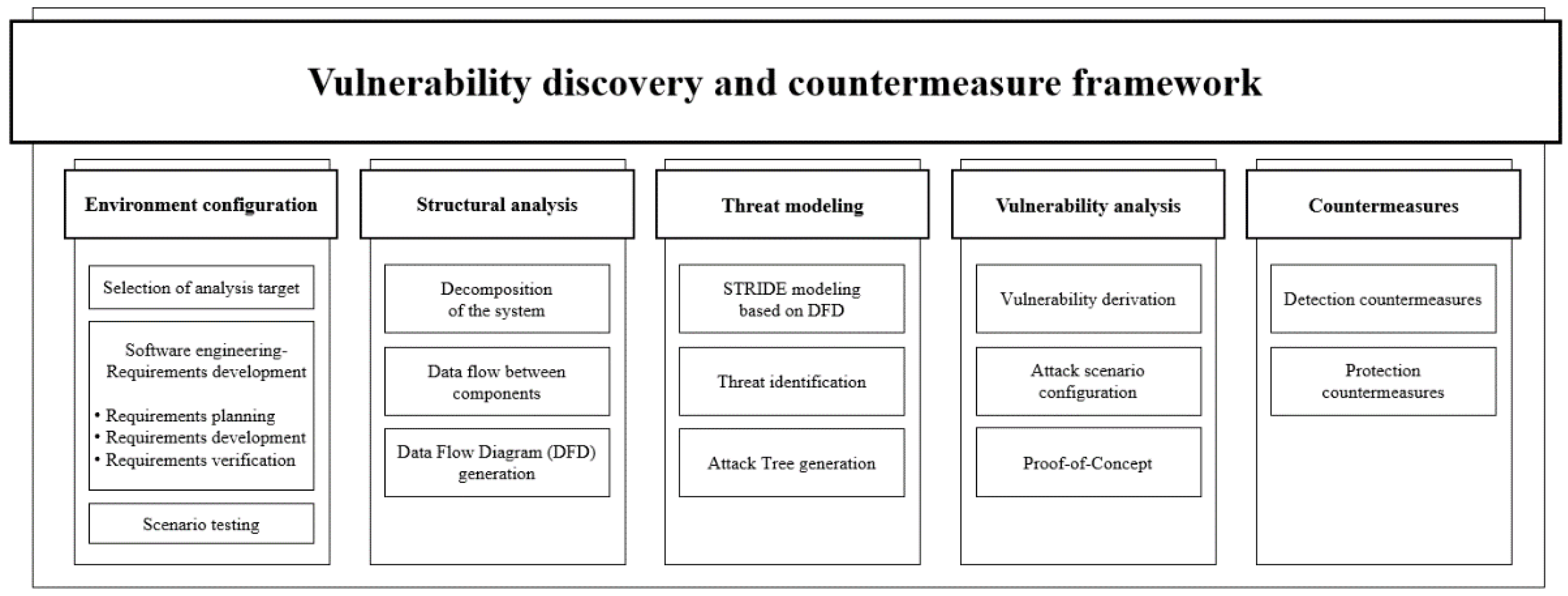
3. Vulnerability Discovery and Countermeasure Framework
3.1. Overview of the Vulnerability Discovery Methodology
- OSSTMM
- 2.
- NIST SP800-115
- Inspection of documents, logs, system configuration, network sniffing, and file integrity;
- Evaluation of vulnerabilities through password cracking, social engineering, and penetration testing;
- Self-assessment of security through reconciliation, data processing, analysis, and evaluation;
- Post-assessment actions with recommendations for risk reduction, assessment reports, and vulnerability patching.
- 3.
- OWASP
- 5.
- OWASP Top 10: A document describing the most well-known vulnerabilities in web and mobile applications, IoT, and APIs. Threats are described in terms of complexity and business impact.
- 6.
- OWASP Testing Guide (TG): This document contains various techniques for testing web application security.
- 7.
- OWASP Developer Guide: This guide provides recommendations for developing safe and reliable code.
- 8.
- OWASP Code Review: This guide is distributed for use by web developers and product managers. It provides an effective method to test the security of existing code.
3.2. Proposed Vulnerability Discovery and Countermeasure Framework
3.2.1. Environment Configuration
3.2.2. Structural Analysis
3.2.3. Threat Modeling
3.2.4. Vulnerability Analysis
3.2.5. Countermeasures
4. Case Study
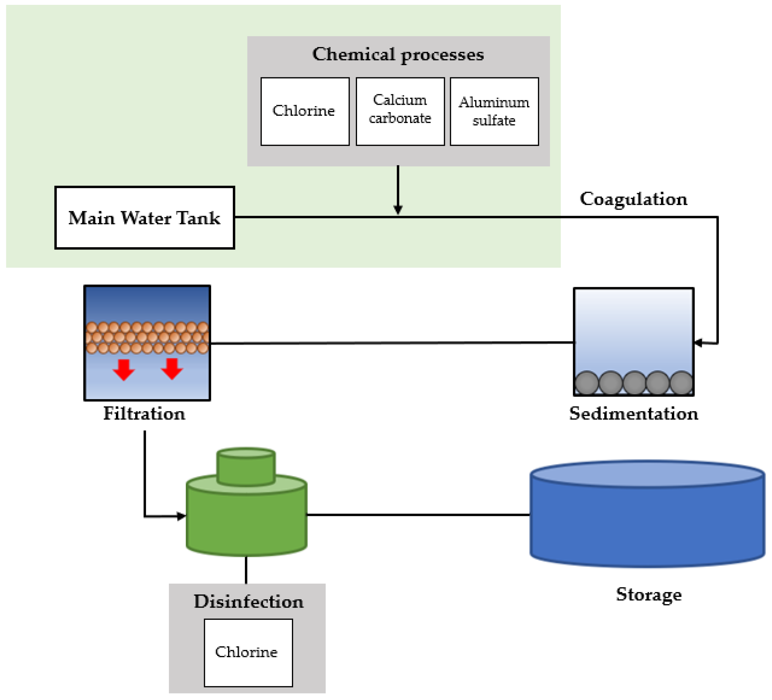
4.1. Environment Configuration
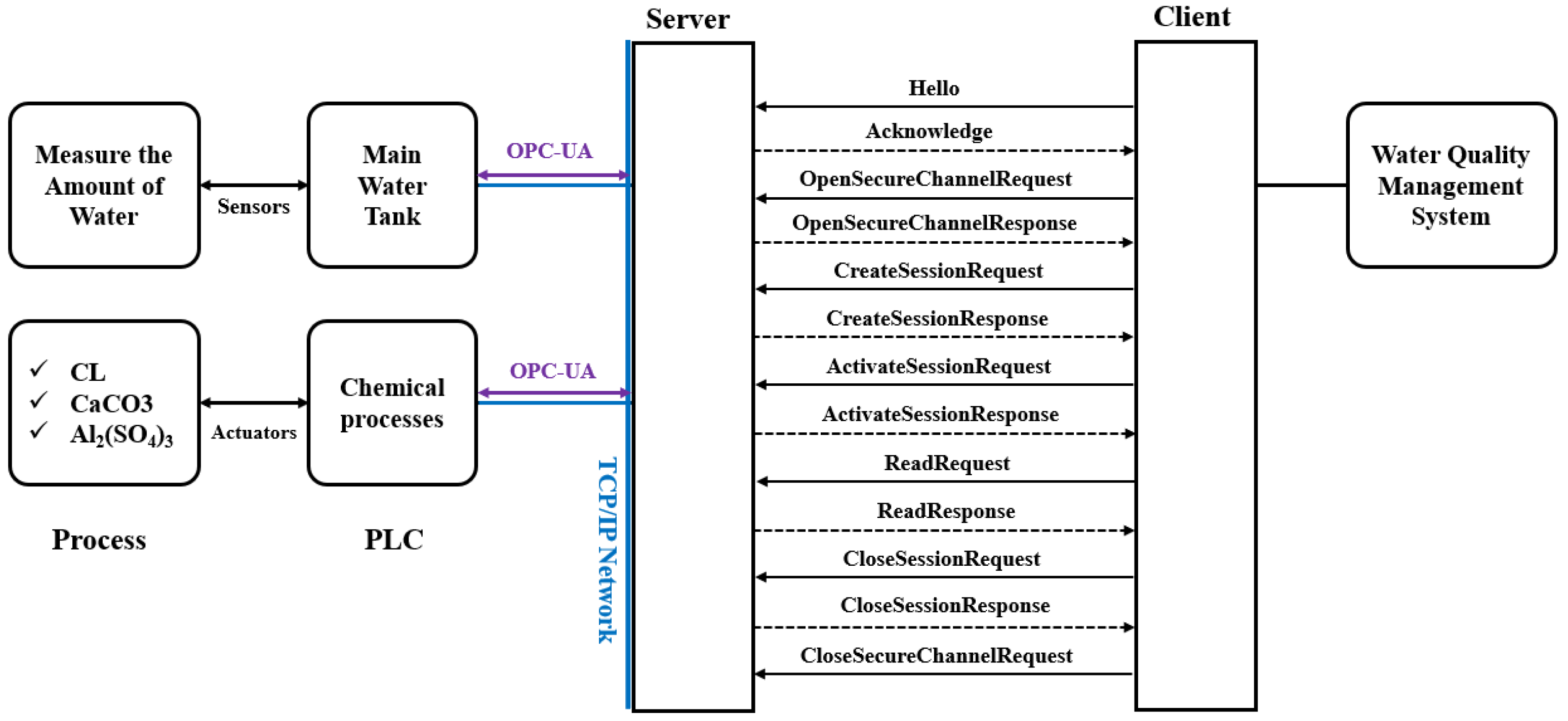
4.2. Structural Analysis
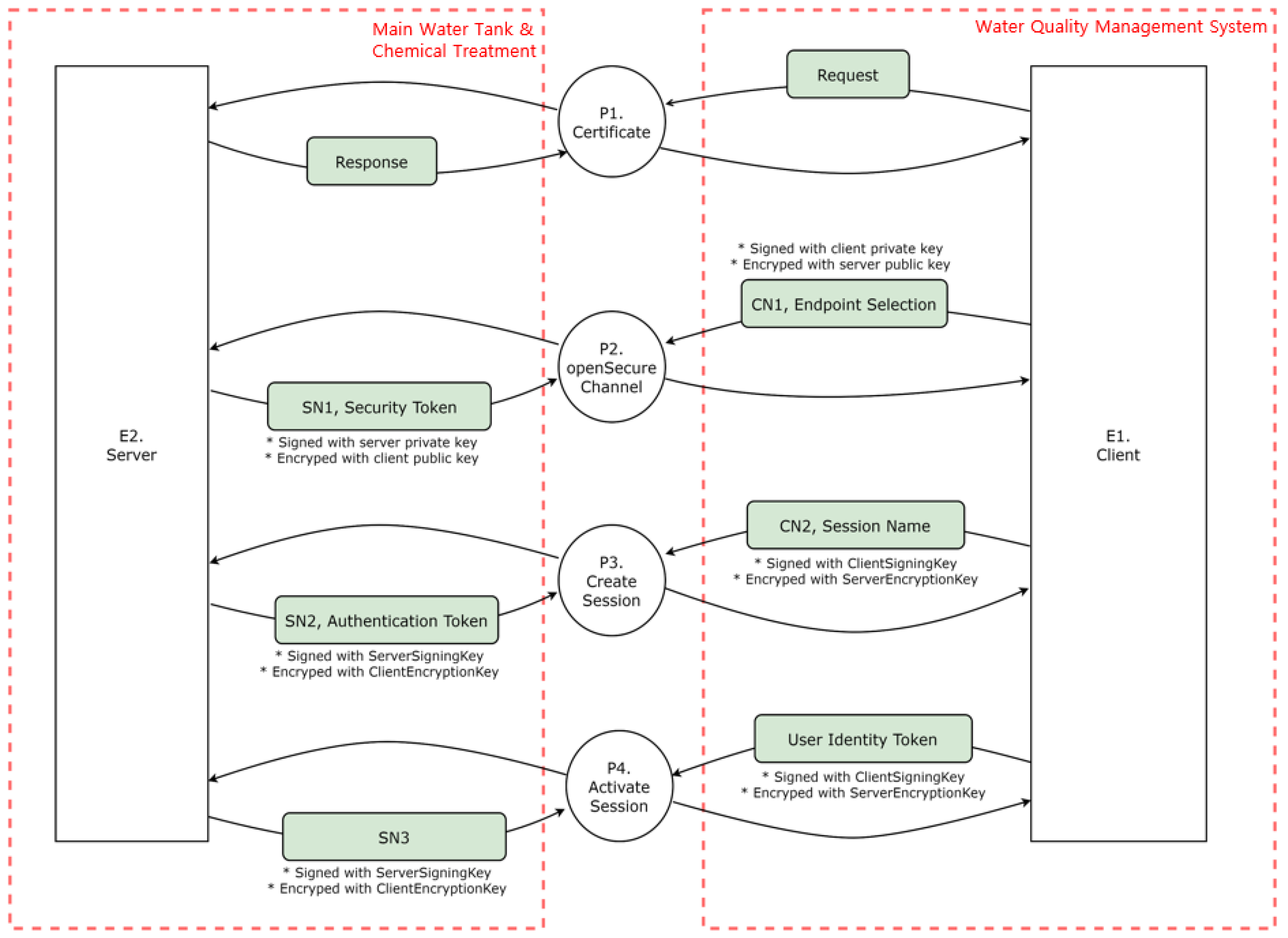
- P1 (Certificate): The server and client exchange requests and responses in the first process.
- P2 (Open secure channel): The client signs its private key through the OpenSecureChannel process, encrypts it with a public key, and sends it to the server. After receiving the transmission, the server signs its private key, encrypts it with a public key, and sends it to the client.
- P3 (Create session): After receiving the transmission, the server signs its private key, encrypts it with a public key, and sends it to the client. After creating a session, the client signs the client signing key, encrypts it with the server’s encryption key, and transmits it to the server. In addition, the server receives the message, signs the server’s signing key, encrypts the client’s encryption key, and delivers it to the client.
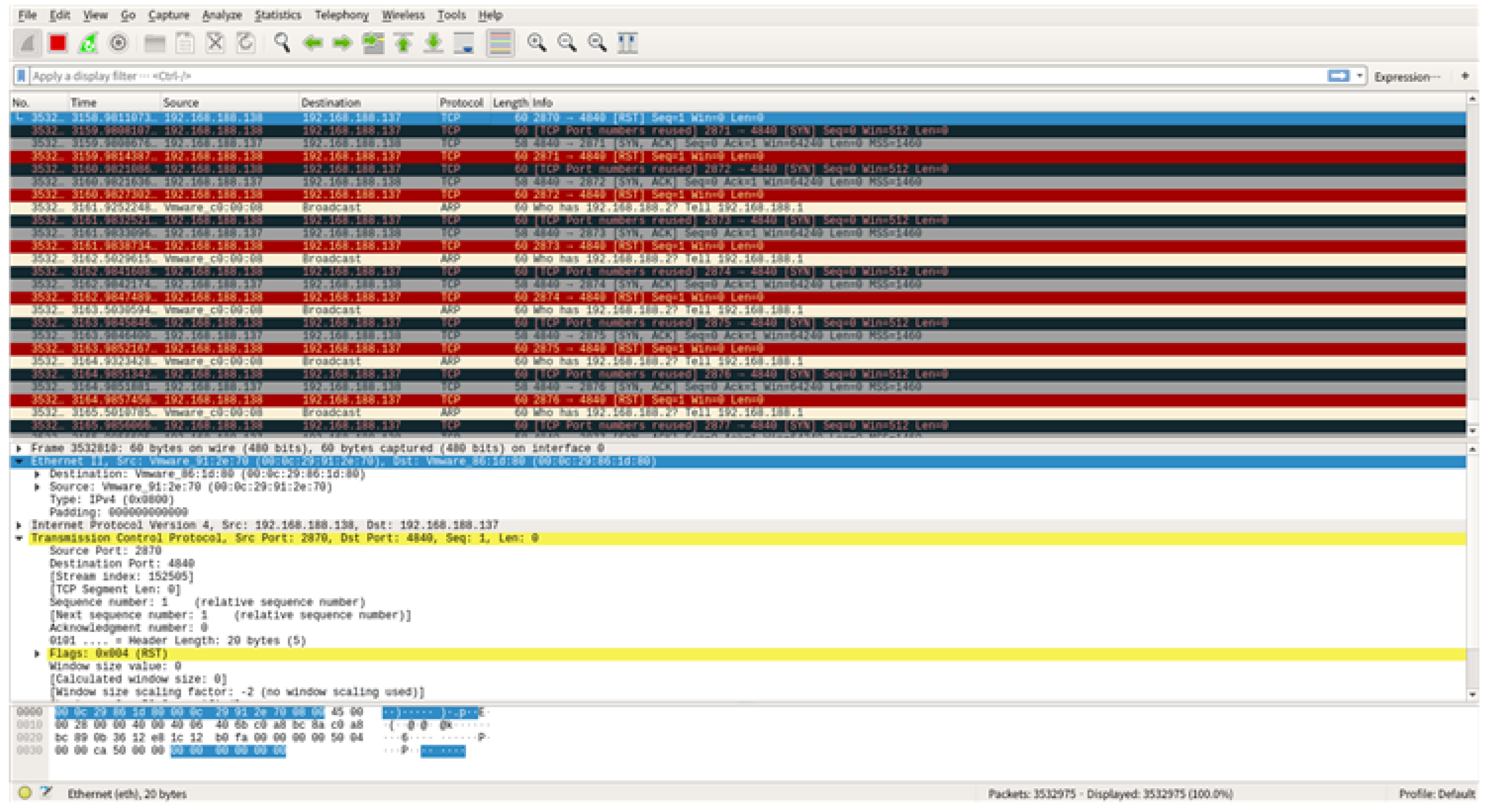
- P4 (Activate session): A user authentication token is sent to the server to activate a session, which the server receives when creating a session and sends it back to the client.A DFD is created based on identifying of the data flow between objects, as illustrated in Figure 11. The external objects are the server and client, and the main processes are authenticating, opening a secure channel, and creating and activating a session. The data flow of the OPC UA server–client system can be monitored by utilizing the Wireshark tool, which is discussed in Section 4.4.3, attack scenario proof-of-concept.
4.3. Threat Modeling
4.4. Vulnerability Analysis
4.4.1. Vulnerability Derivation
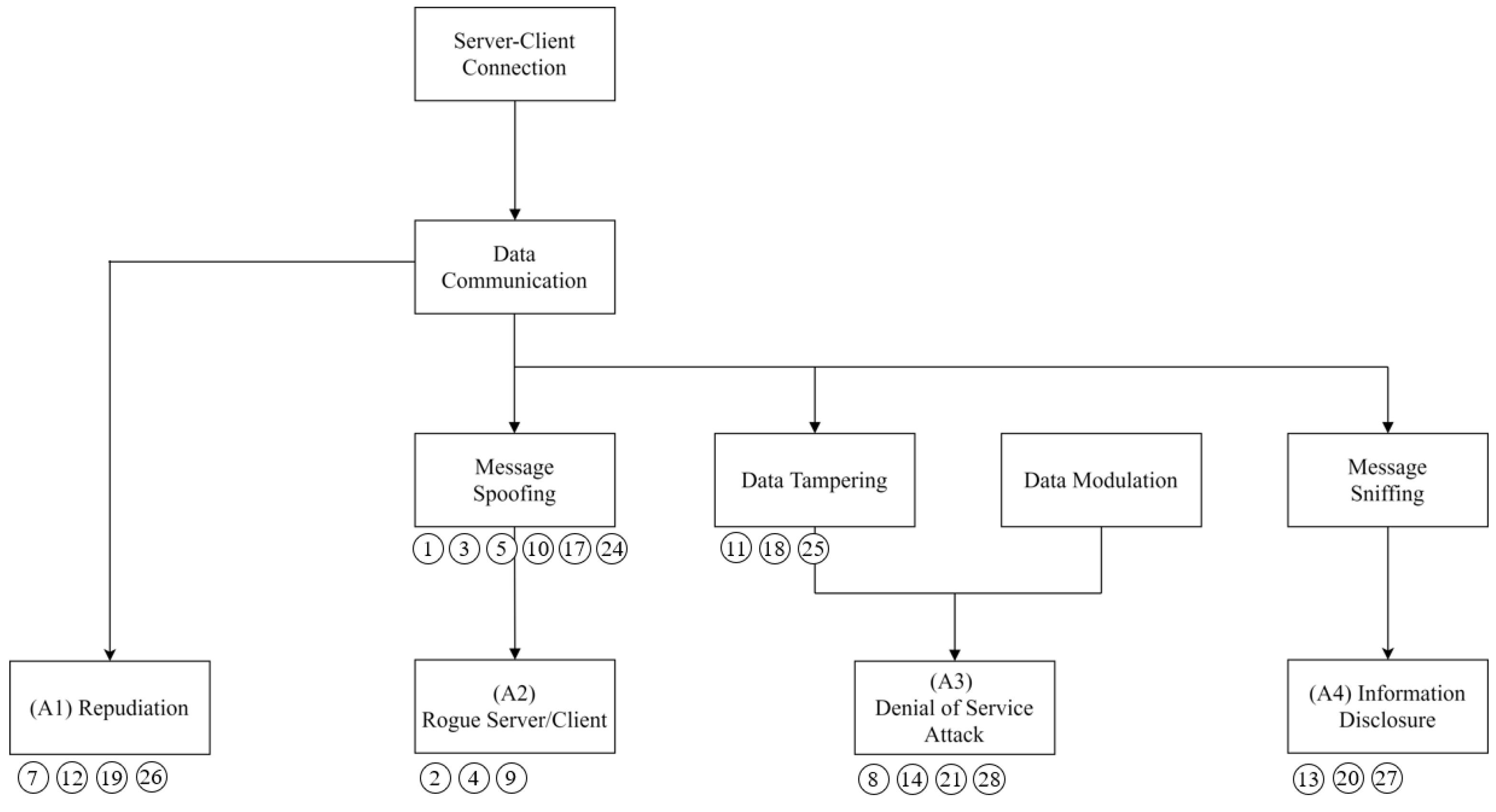
4.4.2. Attack Scenario
- The server runs opcuaServer.py to open port 4840 and waits for a client connection.
- A normal client communicates with the server through socket communication and exchanges keys using the Diffie–Hellman algorithm.
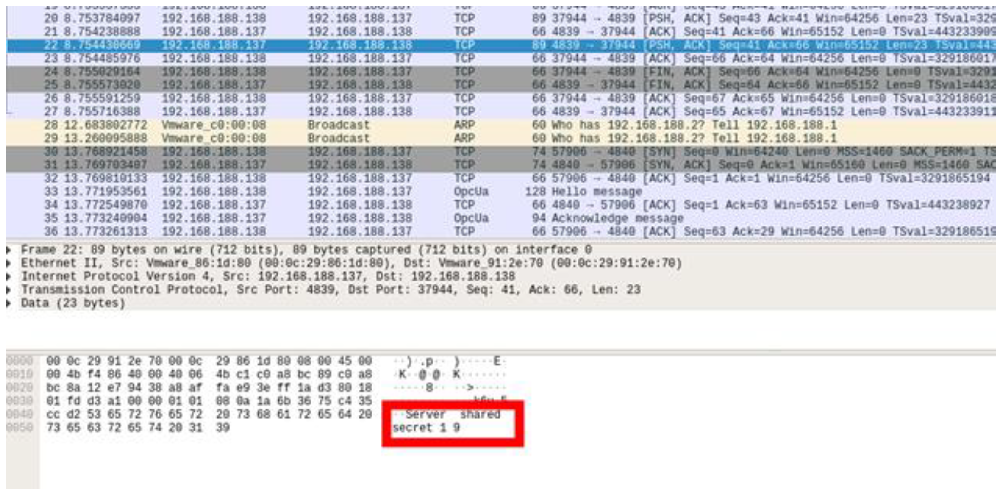
- The rogue client detects the secret key between the server and the normal client.
- The rogue client exchanges the key with the server through the detected secret key and then engages in the authentication process through the forged certificate.
- After the connection process is complete, the rogue client manipulates the sensor and actuator values of the server into abnormal values to perform an attack.
4.4.3. Proof of Concept
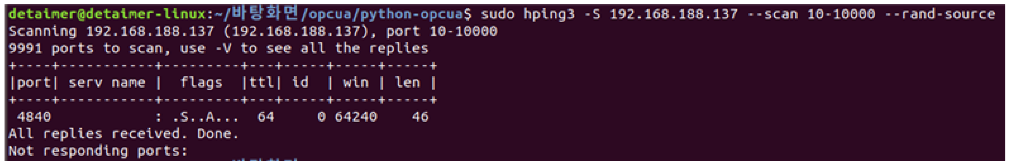
- Port scan step: Scan open ports using the scan parameter.
- 2.
- The SYN flooding attack using hping3: execute the SYN flooding attack using the following command.
4.5. Countermeasures
- Using of encryption algorithms
- 2.
- Certificate management and distribution
- OpenSecureChannel request control
- 2.
- Authenticated client
4.6. Compare the Conventional and Proposed Method
5. Conclusions
Author Contributions
Funding
Institutional Review Board Statement
Informed Consent Statement
Data Availability Statement
Conflicts of Interest
Appendix A

| Element | Element Name | STRIDE | Threat Analysis | Threat Number |
|---|---|---|---|---|
| External Entity | Client | S | Client may be spoofed by an attacker and this may lead to unauthorized access to Process. Consider using a standard authentication mechanism to identify the external entity. | T1 |
| E | Clients may be able to execute code for a process remotely. | T2 | ||
| Server | S | Server may be spoofed by an attacker and this may lead to unauthorized access to Process. Consider using a standard authentication mechanism to identify the external entity. | T3 | |
| E | Server may be able to remotely execute code for Process. | T4 | ||
| Certificate | S | Certificate may be spoofed by an attacker and this may lead to information disclosure by external entity. Consider using a standard authentication mechanism to identify the destination process. | T5 | |
| T | Data flowing across a response may be tampered with by an attacker. This may lead to a DoS or elevation-of -privilege attack against certificate or information disclosure by the certificate. Failure to verify that input is as expected is a root cause of numerous exploitable issues. Consider all paths and the way they handle data. Verify all input using an approved list input validation approach. | T6 | ||
| R | The certificate claims it did not receive data from a source outside the trust boundary. Consider logging or auditing to record the source, time, and summary of the received data. | T7 | ||
| D | The certificate crashes, halts, stops, or runs slowly; in all cases violating an availability metric. | T8 | ||
| E | The certificate may impersonate the context of an external entity to gain additional privilege. | T9 | ||
| Open Security Channel | S | OpenSecure Channel may be spoofed by an attacker, leading to information disclosure by an external entity. Consider using a standard authentication mechanism to identify the destination process. | T10 | |
| T | Data flowing across the CN1, endpoint selection, SN1, and Security token may be tampered with by an attacker, leading to a DoS or elevation-of-privilege attack against the OpenSecure Channel or an information disclosure by OpenSecure Channel. Failure to verify that input is as expected is a root cause of numerous exploitable issues. Consider all paths and the way they handle data. Verify all input using an approved list input validation approach. | T11 | ||
| R | The OpenSecure Channel claims that it did not receive data from a source outside the trust boundary. Consider logging or auditing to record the data source, time, and summary. | T12 | ||
| I | Data flowing across the CN1, endpoint selection, SN1, security token may be sniffed by an attacker. Depending on what type of data an attacker can read, data may be used to attack other system parts or be disclosed, leading to compliance violations. Consider encrypting the data flow. | T13 | ||
| D | The OpenSecure Channel crashes, halts, stops, or runs slowly; in all cases violating an availability metric. | T14 | ||
| E | The OpenSecure Channel may impersonate the context of an external entity to gain additional privilege. | T15 | ||
| E | An attacker may pass data into the OpenSecure Channel to change the program execution flow to the attacker’s choice. | T16 | ||
| Create Session | S | Create session may be spoofed by an attacker, leading to information disclosure by an external entity. Consider using a standard authentication mechanism to identify the destination process. | T17 | |
| T | Data flowing across the CN2, session name, SN2, and authentication token may be tampered with by an attacker, to a DoS or elevation-of-privilege attack against Create Session or an information disclosure by Create Session. Failure to verify that input is as expected is a root cause of numerous exploitable issues. Consider all paths and the way they handle data. Verify all input using an approved list input validation approach. | T18 | ||
| R | Create Session claims it did not receive data from a source outside the trust boundary. Consider logging or auditing to record the data source, time, and summary. | T19 | ||
| I | Data flowing across the CN2, session name, and SN2, authentication token may be sniffed by an attacker. Depending on what type of data an attacker can read, it may be used to attack other parts or be disclosed, leading to compliance violations. Consider encrypting the data flow. | T20 | ||
| D | Create Session crashes, halts, stops, or runs slowly; in all cases violating an availability metric. | T21 | ||
| E | An attacker may pass data into Create Session to change the program execution flow to the attacker’s choice. | T22 | ||
| E | An attacker may pass data into Create Session to change the program execution flow to the attacker’s choice. | T23 | ||
| Activate Session | S | Activate Session may be spoofed by an attacker, and this may lead to information disclosure by an external entity. Consider using a standard authentication mechanism to identify the destination process. | T24 | |
| T | Data flowing across the SN3, and user identity token may be tampered with by an attacker, to a DoS or elevation-of-privilege attack against Activate Session or an information disclosure by Activate Session. Failure to verify that input is as expected is a root cause of numerous exploitable issues. Consider all paths and the way they handle data. Verify all input using an approved list input validation approach. | T25 | ||
| R | Activate Session claims it did not receive data from a source outside the trust boundary. Consider logging or auditing to record the data source, time, and summary. | T26 | ||
| I | Data flowing across SN3, User Identity Token may be sniffed by an attacker. Depending on what type of data an attacker can read, it may be used to attack other system parts or be a disclosure of information leading to compliance violations. Consider encrypting the data flow. | T27 | ||
| D | Activate Session crashes, halts, stops, or runs slowly; in all cases violating an availability metric. | T28 | ||
| E | Activate Session may impersonate the context of an external entity to gain additional privilege. | T29 | ||
| E | An attacker may pass data into Activate Session to change the program execution flow to the attacker’s choice. | T30 |
| Stages | Error/Audit Event | Descriptions |
|---|---|---|
| Certificate structure | - Bad_CertificateInvalid - Bad_SecurityChecksFailed - AuditCertificateInvalidEventType | - Check the certificate structure - No error suppression |
| Build certificate chain | - Bad_CertificateChainIncomplete - Bad_SecurityChecksFailed - AuditCertificateInvalidEventType | - Create a certificate trust chain - Errors may occur during chain creation |
| Signature | - Bad_CertificateInvalid - Bad_SecurityChecksFailed - AuditCertificateInvalidEventType | Reject the certificate if the signature is invalid and the issuing authority is unknown |
| Security policy check | - Bad_CertificatePolicyCheckFailed - Bad_SecurityChecksFailed - AuditCertificateInvalidEventType | Certificate signing complies with the certificate signing algorithm and asymmetric key length algorithm for the user security policy defined in OPC 10000-7 |
| Trust list check | - Bad_CertificateUntrusted - Bad_SecurityChecksFailed - AuditCertificateUntrustedEventType | If the application instance certificate is not trusted and the certificate authority in the chain is not trusted, the certificate validation result will fail |
| Validity period | - Bad_CertificateTimeInvalid - Bad_CertificateIssuerTimeInvalid - AuditCertificateExpiredEventType | Must be within the validity period of the certificate |
| Host name | - Bad_CertificateHostNameInvalid - AuditCertificateDataMismatchEventType | - The hostname in the URL to connect to the server is the same as that of the hostname specified in the certificate - Certificate authority certificates skip this step |
| URI (Uniform Resource Identifier) | - Bad_CertificateUriInvalid - AuditCertificateDataMismatchEventType | - Application and software certificates contain an application or product URI that must match the URI specified in the application description provided with the certificate - Certificate authority certificates skip this step - GatewayServerUri is used to validate the application certificate when connecting to the gateway server |
| Certificate usage | - Bad_CertificateUseNotAllowed - Bad_CertificateIssuerUseNotAllowed - AuditCertificateMismatchEventType | Each certificate must match its intended use (OPC 10000-6) |
| Find revocation list | - Bad_CertificateRevocationUnknown - Bad_CertificateIssuerRevocationUnknown - AuditCertificateRevokedEventType | Each certificate authority certificate has a revocation list, but this step fails if that list is not available |
| Revocation check | - Bad_CertificateRevoked - Bad_CertificateIssuerRevoked - AuditCertificateRevokedEventType | The certificate has been revoked and cannot be used |
References
- Schwarz, M.H.; Börcsök, J. A Survey on OPC and OPC-UA: About the Standard, Developments and Investigations. In Proceedings of the 2013 XXIV International Conference on Information, Communication and Automation Technologies (ICAT), Sarajevo, Bosnia and Herzegovina, 30 October–1 November 2013; pp. 1–6. [Google Scholar]
- OPC Foundation. OPC 10000-2: OPC Unified Architecture. Available online: https://reference.opcfoundation.org/Core/docs/Part2/4.1/ (accessed on 22 July 2022).
- Pohlmann, U.; Sikora, A. Practical security recommendations for building OPC UA applications. In Industrial Ethernet Book; 2018; Volume 106, Available online: https://iebmedia.com/technology/opc-ua/practical-security-guidelines-for-building-opc-ua-applications/ (accessed on 22 July 2022).
- Fiat, M.; Störtkuhl, T.; Plöb, M.; Zugfil, C.; Gappmeier, G.; Damm, M. OPC UA Security Analysis; Federal Office for Information Security: Bonn, Germany, 2017. [Google Scholar]
- OPC Foundation. Security Bulletins. Available online: https://opcfoundation.org/security-bulletins/ (accessed on 22 July 2022).
- Dahlmanns, M.; Lohmöller, J.; Fink, I.B.; Pennekamp, J.; Wehrle, K.; Henze, M. Easing the conscience with OPC UA: An internet-wide study on insecure deployments. In Proceedings of the ACM Internet Measurement Conference, New York, NY, USA, 27–29 October 2020; pp. 101–110. [Google Scholar]
- Kohnhäuser, F.; Meier, D.; Patzer, F.; Finster, S. On the Security of IIoT Deployments: An Investigation of Secure Provisioning Solutions for OPC UA. IEEE Access 2021, 9, 99299–99311. [Google Scholar] [CrossRef]
- Kaspersky. OPC UA Security Analysis. Available online: https://securelist.com/opc-ua-security-analysis/85424/ (accessed on 22 July 2022).
- Puys, M.; Potet, M.-L.; Lafourcade, P. Formal analysis of security properties on the OPC-UA SCADA protocol. In Proceedings of the International Conference on Computer Safety, Reliability, and Security, Trondheim, Norway, 21–23 September 2016; pp. 67–75. [Google Scholar]
- Erba, A.; Müller, A.; Tippenhauer, N.O. Security Analysis of Vendor Implementations of the OPC UA Protocol for Industrial Control Systems. arXiv 2021, arXiv:2104.06051. [Google Scholar]
- Neu, C.V.; Schiering, I.; Zorzo, A. Simulating and detecting attacks of untrusted clients in opc ua networks. In Proceedings of the Proceedings of the Third Central European Cybersecurity Conference, New York, NY, USA, 14–15 November 2019; pp. 1–6. [Google Scholar]
- Varadarajan, V. Security Analysis of OPC UA in Automation Systems for IIoT. 2022. Available online: https://kth.diva-portal.org/smash/get/diva2:1653807/FULLTEXT01.pdf (accessed on 22 July 2022).
- Hildebrandt, M.; Lamshöft, K.; Dittmann, J.; Neubert, T.; Vielhauer, C. Information hiding in industrial control systems: An OPC UA based supply chain attack and its detection. In Proceedings of the 2020 ACM Workshop on Information Hiding and Multimedia Security, New York, NY, USA, 22–24 June 2020; pp. 115–120. [Google Scholar]
- Polge, J.; Robert, J.; Le Traon, Y. Assessing the impact of attacks on opc-ua applications in the industry 4.0 era. In Proceedings of the 2019 16th IEEE Annual Consumer Communications & Networking Conference (CCNC), Las Vegas, NV, USA, 11–14 January 2019; pp. 1–6. [Google Scholar]
- IEC Standard 62264-3:2016; Enterprise-Control System Integration—Part 3: Activity Models of Manufacturing Operations Management. Available online: https://www.iso.org/standard/67480.html (accessed on 22 July 2022).
- HMS Industrial Network. Continued Growth for Industrial Networks Despite Pandemic. Available online: https://www.hms-networks.com/news-and-insights/news-from-hms/2021/03/31/continued-growth-for-industrial-networks-despite-pandemic (accessed on 22 July 2022).
- OPC Foundation. Classic. Available online: https://opcfoundation.org/about/opc-technologies/opc-classic/ (accessed on 22 July 2022).
- OPC Foundation. Unified Architecture. Available online: https://opcfoundation.org/about/opc-technologies/opc-ua/ (accessed on 22 July 2022).
- OMRON. What is OPC UA?—1. Outline of OPC UA “The Industrial Interoperability Standard”. Available online: https://www.ia.omron.com/product/special/sysmac/nx1/opcua.html (accessed on 22 July 2022).
- Renjie, H.; Feng, L.; Dongbo, P. Research on OPC UA security. In Proceedings of the 2010 5th IEEE Conference on Industrial Electronics and Applications, Taichung, Taiwan, 15–17 June 2010. [Google Scholar]
- Roepert, L.; Dahlmanns, M.; Fink, I.B.; Pennekamp, J.; Henze, M. Assessing the Security of OPC UA deployments. arXiv 2020, arXiv:2003.12341. [Google Scholar]
- Cavalieri, S.; Chiacchio, F. Analysis of OPC UA performances. Comput. Stand. Interfaces 2013, 36, 165–177. [Google Scholar] [CrossRef]
- Cavalieri, S.; Cutuli, G.; Monteleone, S. Evaluating impact of security on OPC UA performance. In Proceedings of the 3rd International Conference on Human System Interaction, Rzeszow, Poland, 13–15 May 2010; pp. 687–694. [Google Scholar]
- Torr, P. Demystifying the threat modeling process. IEEE Secur. Priv. 2005, 3, 66–70. [Google Scholar] [CrossRef]
- Howard, M.; Lipner, S. The Security Development Lifecycle; Microsoft Press Redmond: Redmond, Washington, USA, 2006; Volume 8. [Google Scholar]
- Shostack, A. Threat Modeling: Designing for Security; John Wiley & Sons: Hoboken, NJ, USA, 2014. [Google Scholar]
- UcedaVelez, T.; Morana, M.M. Risk Centric Threat Modeling: Process for Attack Simulation and Threat Analysis; John Wiley & Sons: Hoboken, NJ, USA, 2015. [Google Scholar]
- Alberts, C.; Dorofee, A.; Stevens, J.; Woody, C. Introduction to the OCTAVE Approach, Software Engineering Institute. 2003. Available online: https://resources.sei.cmu.edu/library/asset-view.cfm?assetid=51546 (accessed on 22 July 2022).
- Saitta, P.; Larcom, B.; Eddington, M. Trike v. 1 Methodology Document [Draft]. Available online: https://www.octotrike.org/papers/Trike_v1_Methodology_Document-draft.pdf (accessed on 22 July 2022).
- Deng, M.; Wuyts, K.; Scandariato, R.; Preneel, B.; Joosen, W. A privacy threat analysis framework: Supporting the elicitation and fulfillment of privacy requirements. Requir. Eng. 2011, 16, 3–32. [Google Scholar] [CrossRef]
- Wuyts, K. Privacy Threats in Software Architectures. 2015. Available online: https://lirias.kuleuven.be/retrieve/295669 (accessed on 22 July 2022).
- Herzog, P. Open-Source Security Testing Methodology Manual. Institute for Security and Open Methodologies (ISECOM). 2003. Available online: https://sites.radford.edu/~rjoyce9/classes/itec445/code/osstmm.pdf (accessed on 22 July 2022).
- Scarfone, K.; Souppaya, M.; Cody, A.; Orebaugh, A. Technical guide to information security testing and assessment. NIST Spec. Publ. 2008, 800, 2–25. [Google Scholar]
- Meucci, M.; Muller, A. Testing Guide Release 4.0; OWASP Foundation: Bel Air, MD, USA, 2014. [Google Scholar]
- Open62541. Open Source Implementation of OPC UA. Available online: https://github.com/open62541/open62541 (accessed on 22 July 2022).
- OPC Foundation. UA.NET Standard. Available online: https://github.com/OPCFoundation/UA-.NETStandard-Samples (accessed on 22 July 2022).
- node-opcua. An implementation of a OPC UA. Available online: https://github.com/node-opcua/node-opcua (accessed on 22 July 2022).
- FreeOpcUa. Open Source C++ OPC-UA Server and Client Library. Available online: https://github.com/FreeOpcUa/freeopcua (accessed on 22 July 2022).
- python-opcua. LGPL Pure Python OPC-UA Client and Server. Available online: https://github.com/FreeOpcUa/python-opcua (accessed on 22 July 2022).
- openSCADA. OPC-UA Modules. Available online: http://wiki.oscada.org/HomePageEn/Doc/OPCUA (accessed on 22 July 2022).
- OpcUaStack. Open Source OPC UA Application Server and OPC UA Client/Server C++ Libraries. Available online: https://github.com/ASNeG/OpcUaStack (accessed on 22 July 2022).
- OPC Foundation. OPC 10000-6: OPC Unified Architecture. Available online: https://reference.opcfoundation.org/v104/Core/docs/Part6/6.1/ (accessed on 22 July 2022).
- OPC Foundation. OPC 10000-4: OPC Unified Architecture. Available online: https://reference.opcfoundation.org/Core/docs/Part4/6.1.3/ (accessed on 22 July 2022).
- OPC Foundation. OPC 10000-7: OPC Unified Architecture. Available online: https://reference.opcfoundation.org/Core/Part7/ (accessed on 22 July 2022).


| IT | ICS | |
|---|---|---|
| Configuration environment | - Standardized equipment (PC, server) - Short equipment replacement cycle - Easy to patch and repair - Use a universal operating system - Network speed and performance | - Specialized equipment according to the process - Few equipment replacement cycles - Difficult to patch and repair due to equipment availability - General-purpose OS customized (e.g., embedded and kernel) or self-developed OS operation - Real-time network communication is important |
| Critical security objectives | - Block the leakage of important data and service interruption | - Block the possibility of production and process disruption - Prevention of personal accidents in case of accidents |
| Effect on security threats | - Damage caused by leaking important data - Legal issues and damage to company trust | - Direct damage caused by production and human casualties - Damage to product reliability |
| Industrial Control Protocol | Protocol Characteristics |
|---|---|
| PROFINET | Abbreviation for process field net, an open industry standard Ethernet-based protocol built and maintained by PROFINET International (PI) |
| Siemens S7 | Siemens PLC control protocol |
| Modbus | PLC open standard serial communication protocol developed by Modicon |
| OPC-DA | Protocol for real-time data communication between client and server |
| OPC UA | Machine-to-machine communication protocol for industrial automation |
| Industrial Control Protocol | Encryption | Authentication | Security Features at Application Level |
|---|---|---|---|
| Modbus-TCP | - | - | Modbus (No security) |
| DNP3 | Secure DNP | Secure DNP | Secure DNP |
| PROFINET | - | - | - |
| OPC | OPC UA | OPC UA | OPC UA |
| S7Comm | - | - | - |
| Security Purposes | Implementation | |
|---|---|---|
| Reliable information (CIA triad) | Confidentiality | Encryption at the transport layer |
| Integrity | Signing at the transport layer | |
| Availability | Message size limit | |
| Access control (AAA framework) | Authentication | Use of X.509 certificates and user account-based authentication at the application layer |
| Authorization | User role-based access control | |
| Accounting | Generate audit events for security-related actions |
| Author | Year | Attack Type | Description | |
|---|---|---|---|---|
| [8] | Pavel Cheremushkin et al. | 2018 | DoS, Remote code execution | OPC UA penetration testing using fuzzing techniques |
| [9] | Puys, Maxime et al. | 2016 | Privilege escalation | Validation of OPC UA confidentiality and security of authentication attributes using a cryptographic protocol verification tool |
| [10] | Erba, Alessandro et al. | 2021 | MiTM | Security evaluation and vulnerability attack verification for commercial OPC UA products |
| [11] | Neu, Charles Varlei et al. | 2019 | DoS | Implementation and evaluation of DoS attack scenarios for OPC UA clients not using the secure mode |
| [12] | Varadarajan, Vaishnavi | 2022 | Packet sniffing, MiTM, DoS | Implementing attack simulations for the three most common types of attacks in the IoT |
| [13] | Hildebrandt, Mario et al. | 2020 | Supply chain attack | Supply chain attack verification through the OPC UA server–client hidden channel |
| [14] | Polge, Julien et al. | 2019 | MiTM, message flooding | OPC UA threat modeling and attack scenario implementation based on IoT threat modeling |
| STRIDE | Security Attributes | Description |
|---|---|---|
| Spoofing | Authentication | Acquiring privileges using an illegal account |
| Tampering | Integrity | Illegal changing of data |
| Repudiation | Non-repudiation | Disclaiming failure to perform certain services or disclaiming liability |
| Information disclosure | Confidentiality | Giving information to someone who does not have access |
| DoS | Availability | Preventing a service or application from performing normally |
| Elevation of privilege | Authorization | Authorizing someone to perform an unauthorized service |
| Object | Confidentiality | Integrity | Availability | Authentication | Authorization | Auditability | Non-Repudiation | |
|---|---|---|---|---|---|---|---|---|
| Threat | ||||||||
| OPC UA | 2, 7, 8, 9, 10, 11 | 3, 4, 6, 7, 8, 9 | 1, 6, 7, 8, 9,10 | 2, 4, 5, 7, 8, 9, 10, 11 | 2, 3, 4, 5, 7, 8, 9, 10, 11 | 4, 7, 8, 9, 10 | 4, 7, 8, 12 | |
| STRIDE | I | T | D | E | S | - | R | |
| Trike | Elevation of Privilege | Elevation of Privilege | Denial of Service | Elevation of Privilege | ||||
| OCTAVE | - | - | - | - | - | - | - | |
| LINDDUN | Disclosure of information (D), Detectability (D) | - | - | Identifiability(I), Linkability(L) | Identifiability(I) | Non-compliance (N) | Non-repudiation (N) | |
| PASTA | - | - | - | - | - | - | - | |
| Main Direction | Description |
|---|---|
| Human security | Security aspects that deal with direct physical or psychological interactions between people |
| Physical security | A security aspect that covers all material elements of security, whether physically or electromechanically actuated |
| Wireless communications | Security of all wireless communications and devices from Wi-Fi to infrared sensors |
| Telecommunications | Tests all communications over the network, whether the communications network is digital or analog |
| Data networks | Data network security testing involves electronic systems and data networks used to communicate or interact over cable and wired network lines |
| Component | Symbol | Description |
|---|---|---|
| External entity |  | External objects create data inputs and check outputs |
| Data store |  | Data stores store data temporarily or permanently |
| Process |  | Processes are responsible for taking data input and generating output |
| Data flow |  | Data flow refers to the movement of data between objects |
| Trust boundary |  | Trust boundaries represent changes in privilege levels |
| No. | Name | Language | Client/Server |
|---|---|---|---|
| 1 | Open62541 [35] | C | Client and server |
| 2 | UA.NET Standard [36] | C# | Client and server |
| 3 | node-opcua [37] | JavaScript | Client and server |
| 4 | FreeOpcUa [38] | C++ | Client and server |
| 5 | Python FreeOpcUa [39] | Python | Client and server |
| 6 | OpenScada UA Interface [40] | C++ | Server |
| 7 | ASNeG [41] | C++ | Client and server |
| No. | Server | Client |
|---|---|---|
| Connection with the server (Channel and session) | Create channels and sessions | |
| View and read property values | Get the path and node | |
| Add/remove nodes | Events | |
| Call method | Methods | |
| Username/password | Encryption | |
| Certificate login | Certificate handling | |
| Communication encryption | Change data |
| Open-Source List | Server | Client | ||||||||||||
|---|---|---|---|---|---|---|---|---|---|---|---|---|---|---|
| Open62541 | ✓ | ✓ | ✓ | ✓ | - | - | ✓ | ✓ | ✓ | ✓ | ✓ | ✓ | - | ✓ |
| UA.NET Standard | ✓ | ✓ | ✓ | ✓ | ✓ | ✓ | ✓ | ✓ | ✓ | ✓ | ✓ | ✓ | ✓ | ✓ |
| node-opcua | ✓ | ✓ | ✓ | ✓ | ✓ | ✓ | ✓ | ✓ | ✓ | ✓ | ✓ | ✓ | ✓ | ✓ |
| FreeOpcUa | ✓ | ✓ | ✓ | ✓ | - | - | - | ✓ | ✓ | ✓ | ✓ | - | - | ✓ |
| Python FreeOpcUa | ✓ | ✓ | ✓ | ✓ | ✓ | ✓ | ✓ | ✓ | ✓ | ✓ | ✓ | ✓ | ✓ | ✓ |
| OpenScada UA Interface | ✓ | ✓ | ✓ | ✓ | ✓ | ✓ | ✓ | - | - | - | - | - | - | - |
| ASNeG | ✓ | ✓ | ✓ | ✓ | - | - | - | ✓ | ✓ | ✓ | ✓ | - | - | ✓ |
| Element | Name | Sign |
|---|---|---|
| External object | Client | E1 |
| Server | E2 | |
| Process | Certificate | P1 |
| Open Secure Channel | P2 | |
| Create Session | P3 | |
| Activate Session | P4 |
| Threat | S | T | R | I | D | E |
|---|---|---|---|---|---|---|
| External entity | ✓ | ✓ | ||||
| Data flow | ✓ | ✓ | ✓ | ✓ | ✓ | ✓ |
| Attack Types | Attack Descriptions |
|---|---|
| A1 | Creates trust issues through denial of data by the sender and receiver |
| A2 | Manipulates clients by stealing credentials |
| A3 | An untrusted client/server exists on the same network and continuously sends messages to flood the network and OPC UA server to perform a DoS attack |
| A4 | Steals server/client information |
| Server | Client | |
|---|---|---|
| Python file | opcuaServer.py | opcuaClient.py |
| Certification | certificate-example.der | my_cert.der |
| private-key-example.pem | client_private_key.pem | |
| Symmetric key storage file | serverkey.txt | serverkey.txt |
| client.txt | client.txt |
| Parameters | Descriptions |
|---|---|
| -S | SYN flag setting |
| <IP_ADDRESS> | Destination IP |
| --scan | SCAN mode |
| -p | Set destination port number |
| --rand-source | Send source IP randomly |
| --flood | Sending many packets in a short time |
| Attacker | Victim | |
|---|---|---|
| IP Address | 192.168.188.143 | 192.168.188.142 |
| Condition | Attack using hping3 | Listening status |
| Algorithm Name | Description |
|---|---|
| PolicyUri | URI assigned to the security policy |
| SymmetricSignatureAlgorithm | Symmetric signature algorithm |
| SymmetricEncryptionAlgorithm | Symmetric encryption algorithm |
| AsymmetricSignatureAlgorithm | Asymmetric signature algorithm |
| AsymmetricEncryptionAlgorithm | Asymmetric encryption algorithm |
| MinAsymmetricKeyLength | Minimum length of the asymmetric key |
| MaxAsymmetricKeyLength | Maximum length of the asymmetric key |
| KeyDerivationAlgorithm | Key derivation algorithm |
| DerivedSignatureKeyLength | Bit length of the derived key to authenticate a message |
| CertificateSignatureAlgorithm | Asymmetric signing algorithm to sign certificates |
| SecureChannelNonceLength | Length (in bytes) of nonces exchanged when creating a secure channel |
| Conventional Method | Proposed Framework | ||
|---|---|---|---|
| OSSTMM | OWASP-TG | ||
| Testing Steps | 6 phases | 5 phases | 5 phases |
| Countermeasure | X | O | O |
| Features | Applicable to IT systems | Applicable to Web | Applicable to operational technology (OT) system |
Publisher’s Note: MDPI stays neutral with regard to jurisdictional claims in published maps and institutional affiliations. |
© 2022 by the authors. Licensee MDPI, Basel, Switzerland. This article is an open access article distributed under the terms and conditions of the Creative Commons Attribution (CC BY) license (https://creativecommons.org/licenses/by/4.0/).
Share and Cite
Shin, D.-H.; Kim, G.-Y.; Euom, I.-C. Vulnerabilities of the Open Platform Communication Unified Architecture Protocol in Industrial Internet of Things Operation. Sensors 2022, 22, 6575. https://doi.org/10.3390/s22176575
Shin D-H, Kim G-Y, Euom I-C. Vulnerabilities of the Open Platform Communication Unified Architecture Protocol in Industrial Internet of Things Operation. Sensors. 2022; 22(17):6575. https://doi.org/10.3390/s22176575
Chicago/Turabian StyleShin, Dong-Hyuk, Ga-Yeong Kim, and Ieck-Chae Euom. 2022. "Vulnerabilities of the Open Platform Communication Unified Architecture Protocol in Industrial Internet of Things Operation" Sensors 22, no. 17: 6575. https://doi.org/10.3390/s22176575
APA StyleShin, D.-H., Kim, G.-Y., & Euom, I.-C. (2022). Vulnerabilities of the Open Platform Communication Unified Architecture Protocol in Industrial Internet of Things Operation. Sensors, 22(17), 6575. https://doi.org/10.3390/s22176575