A Dispersion Compensation Method Based on Resampling of Modulated Signal for FMCW Lidar


Abstract
1. Introduction
2. Theoretical Principles and Models
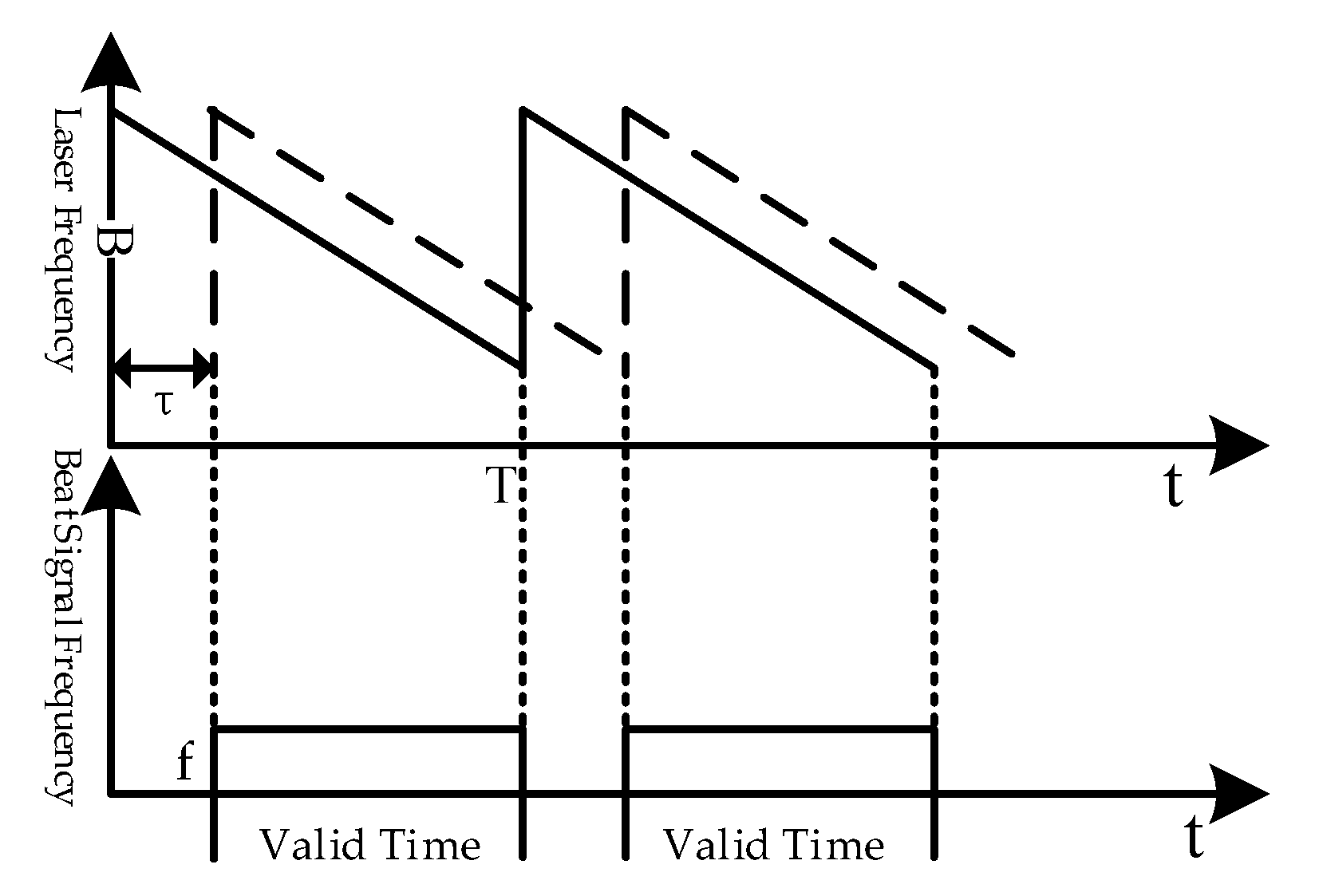
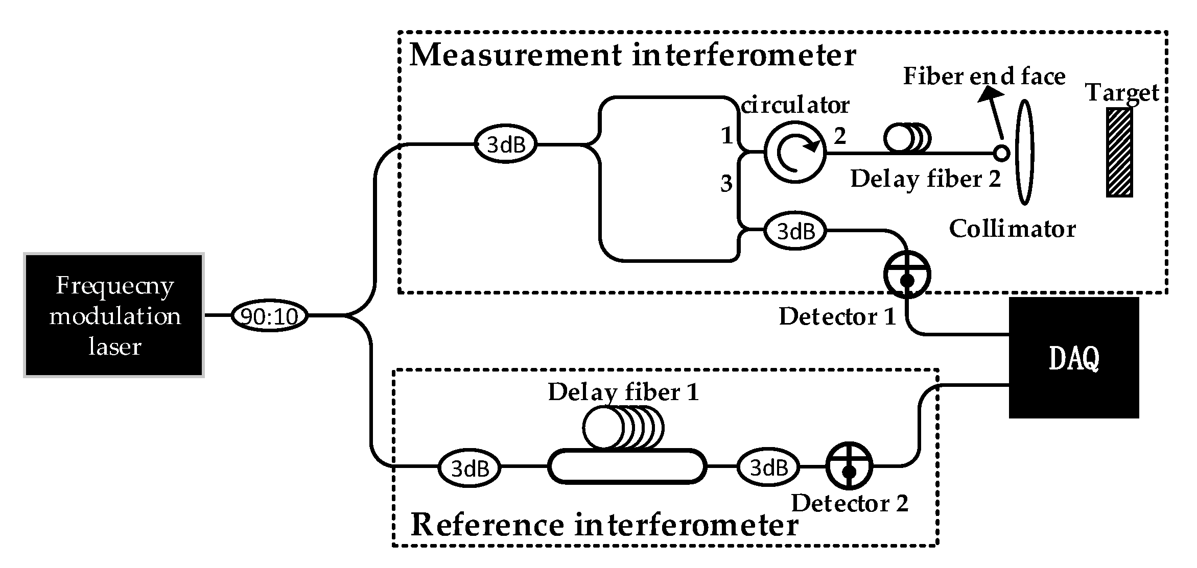
2.1. The Ranging Process of FMCW Lidar
2.2. Influence of Optical Fiber Dispersion of Reference Interferometer on Ranging
2.3. Dispersion Compensation Method Based on Resampling of Modulated Signal
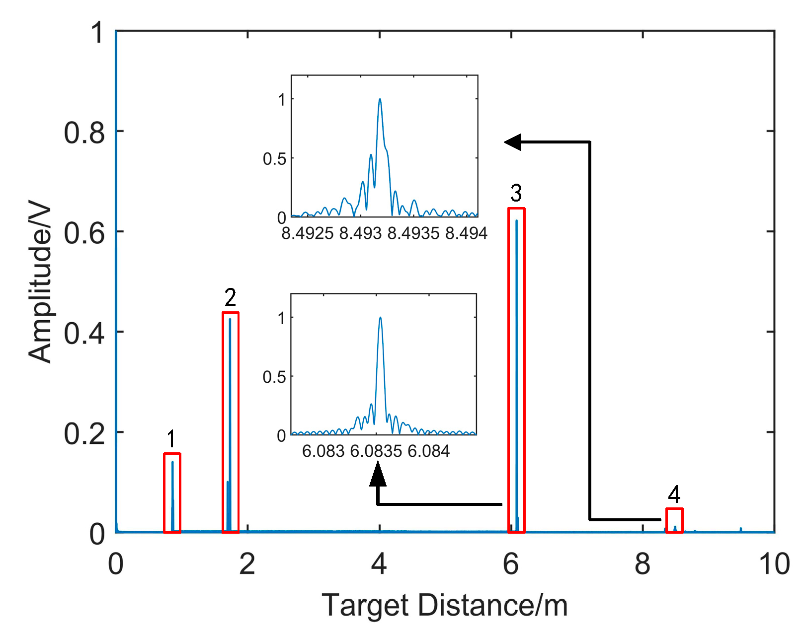
- The resampling signal of the laser leakage from port 1 to 3 of the circulator;
- The resampling signal of the laser reflected from port 2 to 3 of the circulator;
- The reflected resampling signal from the end face of delay fiber 2;
- The resampling target signal.
3. Experimental Results and Analysis
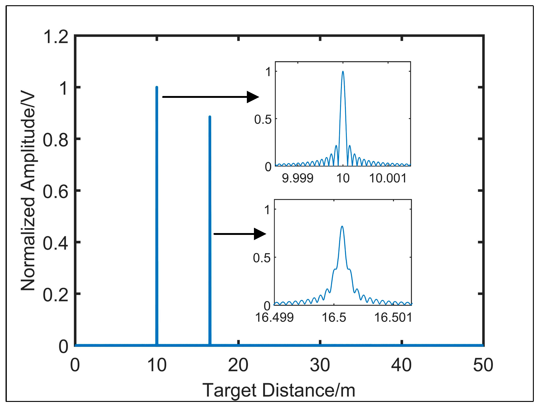
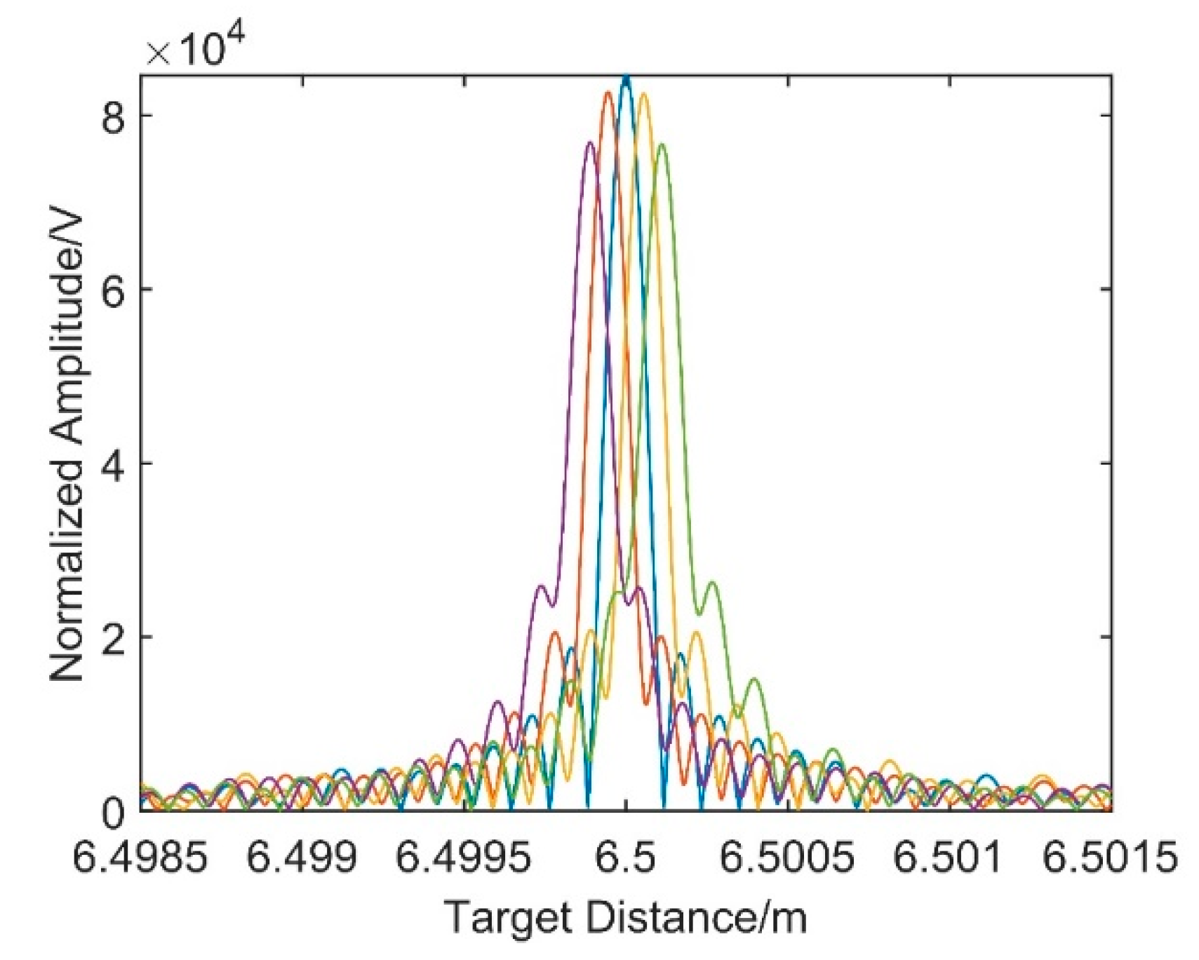
3.1. Simulation
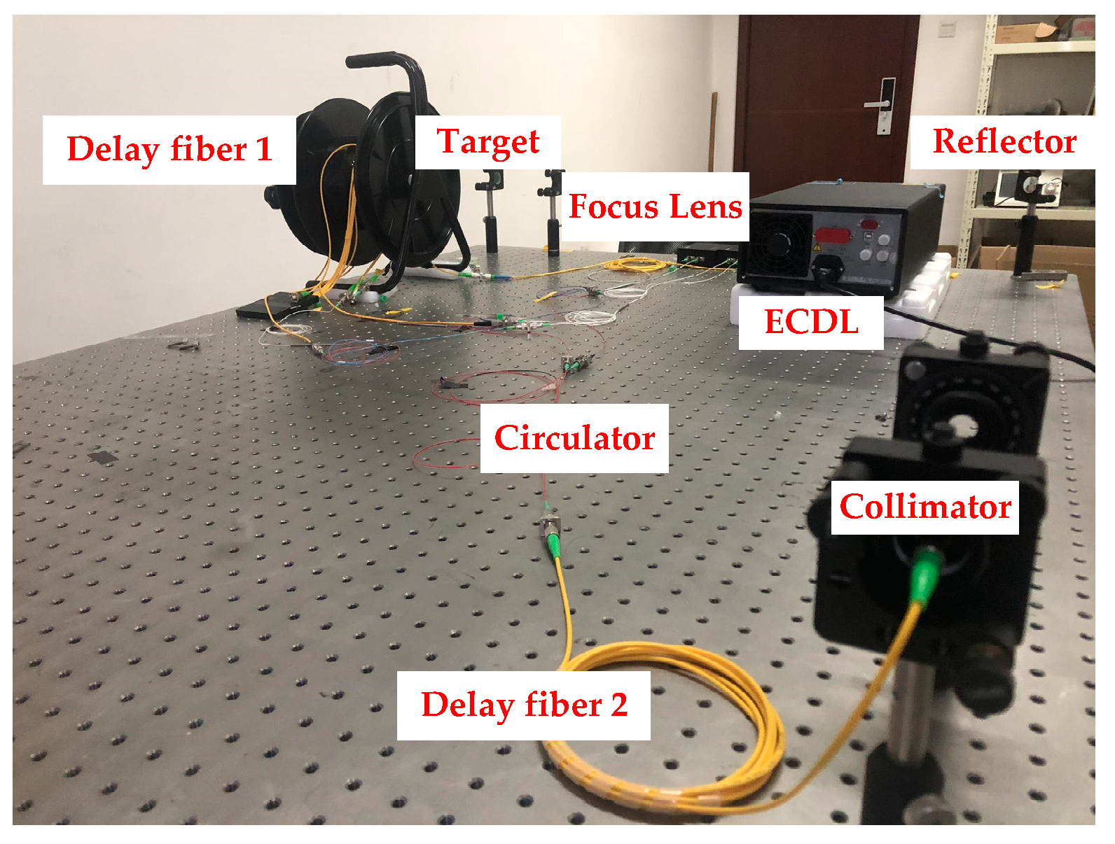
3.2. Experiment
4. Discussion
5. Conclusions
Author Contributions
Funding
Institutional Review Board Statement
Informed Consent Statement
Data Availability Statement
Acknowledgments
Conflicts of Interest
References
- Zhaoyu, L.; Chunfeng, G.; Zhaoyin, W. Basics and developments of frequency modulation continuous wave LiDAR. Opto-Electron. Eng. 2019, 46, 7–20. (In Chinese) [Google Scholar]
- Guang, S.; Fumin, Z.; Xinghua, Q. Absolute distance measurement by high resolution frequency modulated continuous wave laser. Acta Phys. Sin. 2014, 63, 269–274. [Google Scholar]
- Swinkels, B.L.; Bhattacharya, N.; Wielders, A. Absolute distance metrology for space interferometers. SPIE Opt. Metrol. 2005, 554, 559–561. [Google Scholar]
- Coe, P.A.; Howell, D.F.; Nickerson, R.B. Frequency scanning interferometry in ATLAS: Remote, multiple, simultaneous and precise distance measurements in a hostile environment. Meas. ENCE Technol. 2004, 15, 2175–2187. [Google Scholar] [CrossRef]
- Yang, H.J.; Nyberg, S.; Riles, K. High-precision Absolute Distance Measurement using Dual-Laser Frequency Scanned Interferometry Under Realistic Conditions. Nucl. Inst. Methods Phys. Res. A 2006, 575, 395–401. [Google Scholar] [CrossRef]
- Cabral, A.; Rebordao, J. Absolute distance metrology with frequency sweeping interferometry. Proc. SPIE 2005, 5879, 195–204. [Google Scholar]
- Minfu, Z.; Xinghua, Q.; Shenghua, Y. Multiple sensor fusion in large scale measurement. Opt. Precis. Eng. 2008, 16, 1236–1240. [Google Scholar]
- Shi, G.; Zhang, F.; Qu, X. High-resolution frequency-modulated continuous-wave laser ranging for precision distance metrology applications. Opt. Eng. 2014, 53, 122402. [Google Scholar] [CrossRef]
- Fouche, D.G.; Daniel, G. Doppler imaging with dual-detection full-range frequency domain optical coherence tomography. Detection and false-alarm probabilities for laser radars that use Geiger-mode detectors. Appl. Opt. 2003, 42, 5388–5398. [Google Scholar] [CrossRef] [PubMed]
- Asaka, K.; Ohbayashi, K. Dispersion matching of sample and reference arms in optical frequency domain reflectometry-optical coherence tomography using a dispersion-shifted fiber. Opt. Express 2007, 15, 5030–5042. [Google Scholar] [CrossRef] [PubMed]
- Lippok, N.; Stephane, C.; Nielsen, P. Dispersion compensation in Fourier domain optical coherence tomography using the fractional Fourier transform. Opt. Express 2012, 20, 23398. [Google Scholar] [CrossRef] [PubMed]
- Lu, C.; Liu, G.; Liu, B. Method based on chirp decomposition for dispersion mismatch compensation in precision absolute distance measurement using swept-wavelength interferometry. Opt. Express 2015, 23, 31662–31671. [Google Scholar] [CrossRef] [PubMed]
- Chundao, S.; Fumin, S.; Hao, P. Dispersion correction in large-length range finding of frequency modulation continuous wave (FMCW). J. Infrared Millim. Waves 2018, 37, 642–648. [Google Scholar]
- Xinke, X.; Guodong, L.; Bingguo, L. High-resolution laser frequency scanning interferometer based on fiber dispersion phase compensation. Acta Phys. Sin. 2015, 64, 474–486. [Google Scholar]


| Modulation | ||||
| 2 | 100 | |||
| The OPD of Delay Fiber 2 | Spatial Distance of the Target | Sampling Frequency | ||
| 10 | 6.5 | 8 |
Publisher’s Note: MDPI stays neutral with regard to jurisdictional claims in published maps and institutional affiliations. |
© 2021 by the authors. Licensee MDPI, Basel, Switzerland. This article is an open access article distributed under the terms and conditions of the Creative Commons Attribution (CC BY) license (http://creativecommons.org/licenses/by/4.0/).
Share and Cite
Jiang, S.; Liu, B.; Wang, S. A Dispersion Compensation Method Based on Resampling of Modulated Signal for FMCW Lidar. Sensors 2021, 21, 249. https://doi.org/10.3390/s21010249
Jiang S, Liu B, Wang S. A Dispersion Compensation Method Based on Resampling of Modulated Signal for FMCW Lidar. Sensors. 2021; 21(1):249. https://doi.org/10.3390/s21010249
Chicago/Turabian StyleJiang, Shuo, Bo Liu, and Shengjie Wang. 2021. "A Dispersion Compensation Method Based on Resampling of Modulated Signal for FMCW Lidar" Sensors 21, no. 1: 249. https://doi.org/10.3390/s21010249
APA StyleJiang, S., Liu, B., & Wang, S. (2021). A Dispersion Compensation Method Based on Resampling of Modulated Signal for FMCW Lidar. Sensors, 21(1), 249. https://doi.org/10.3390/s21010249