A Review of Coating Materials Used to Improve the Performance of Optical Fiber Sensors

Abstract
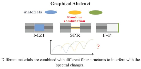
1. Introduction
2. Sensors Coated with the PDMS
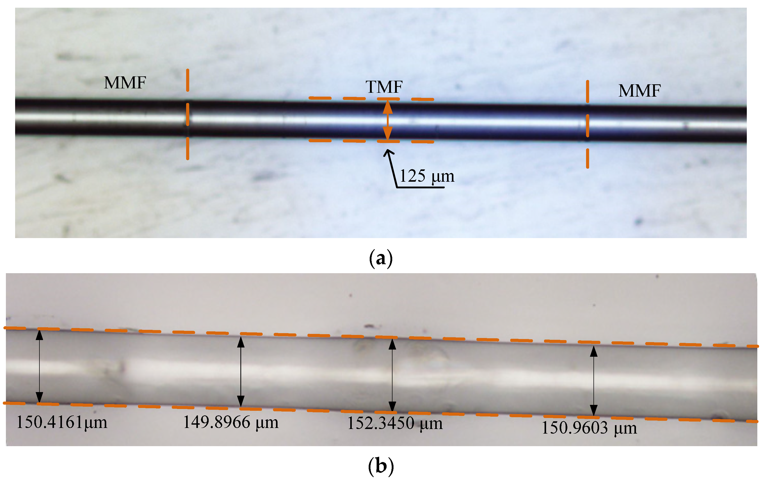
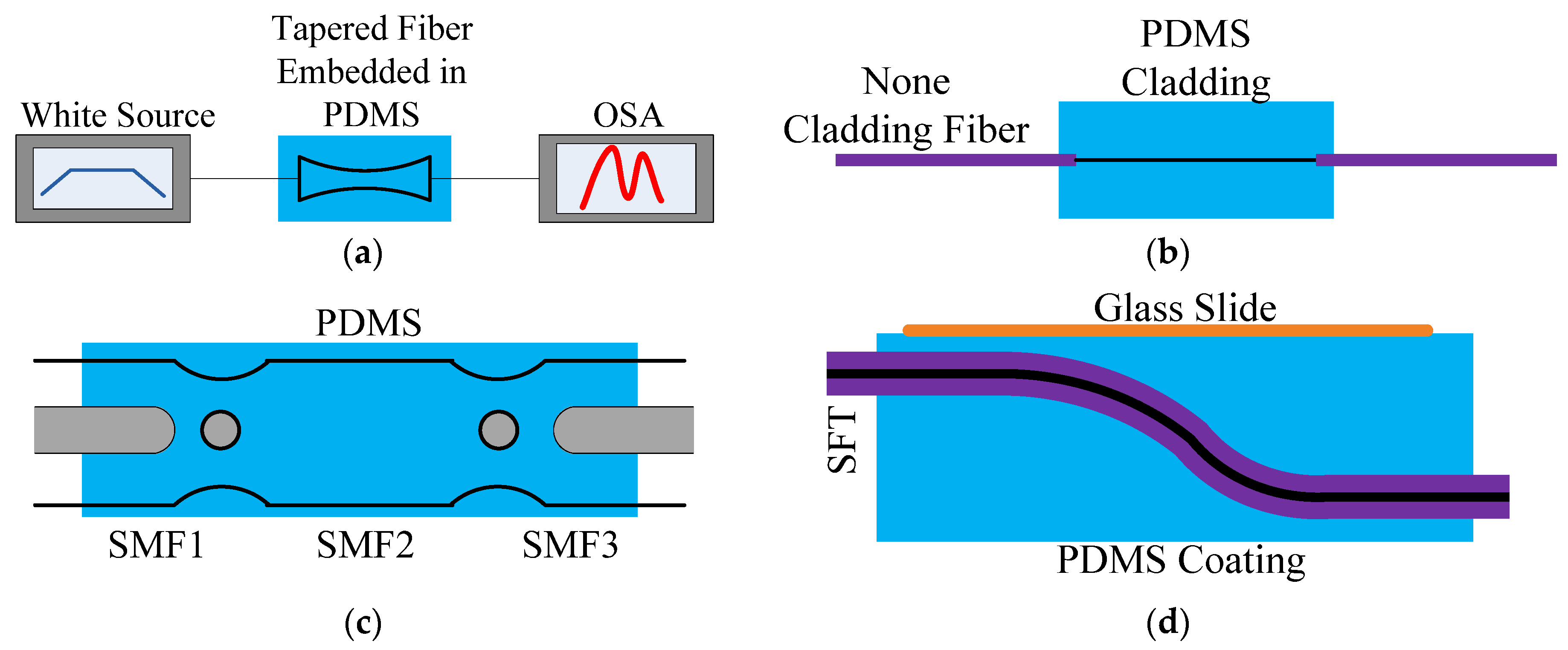
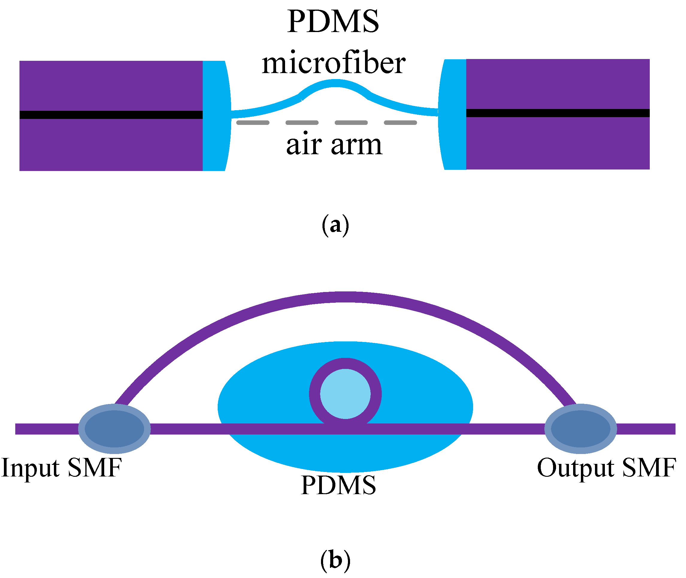
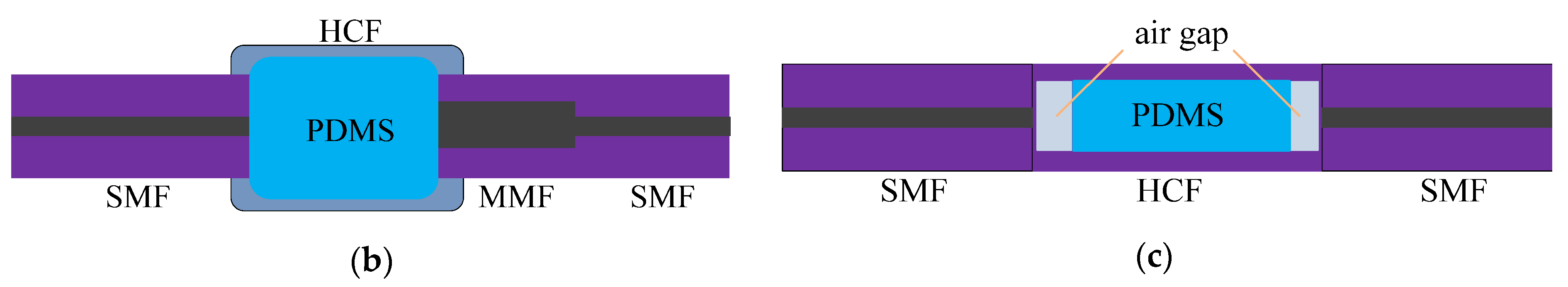
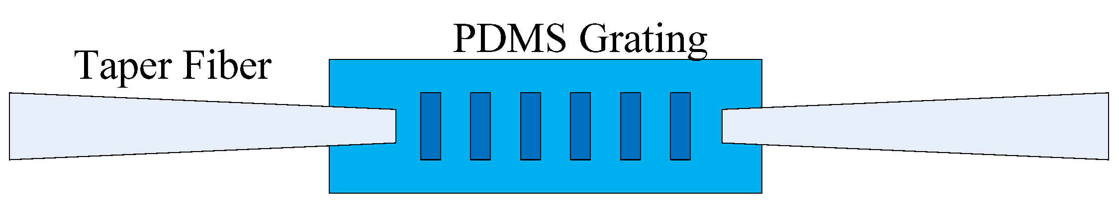
2.1. A Variety of Structures Based on Mach–Zehnder Interference
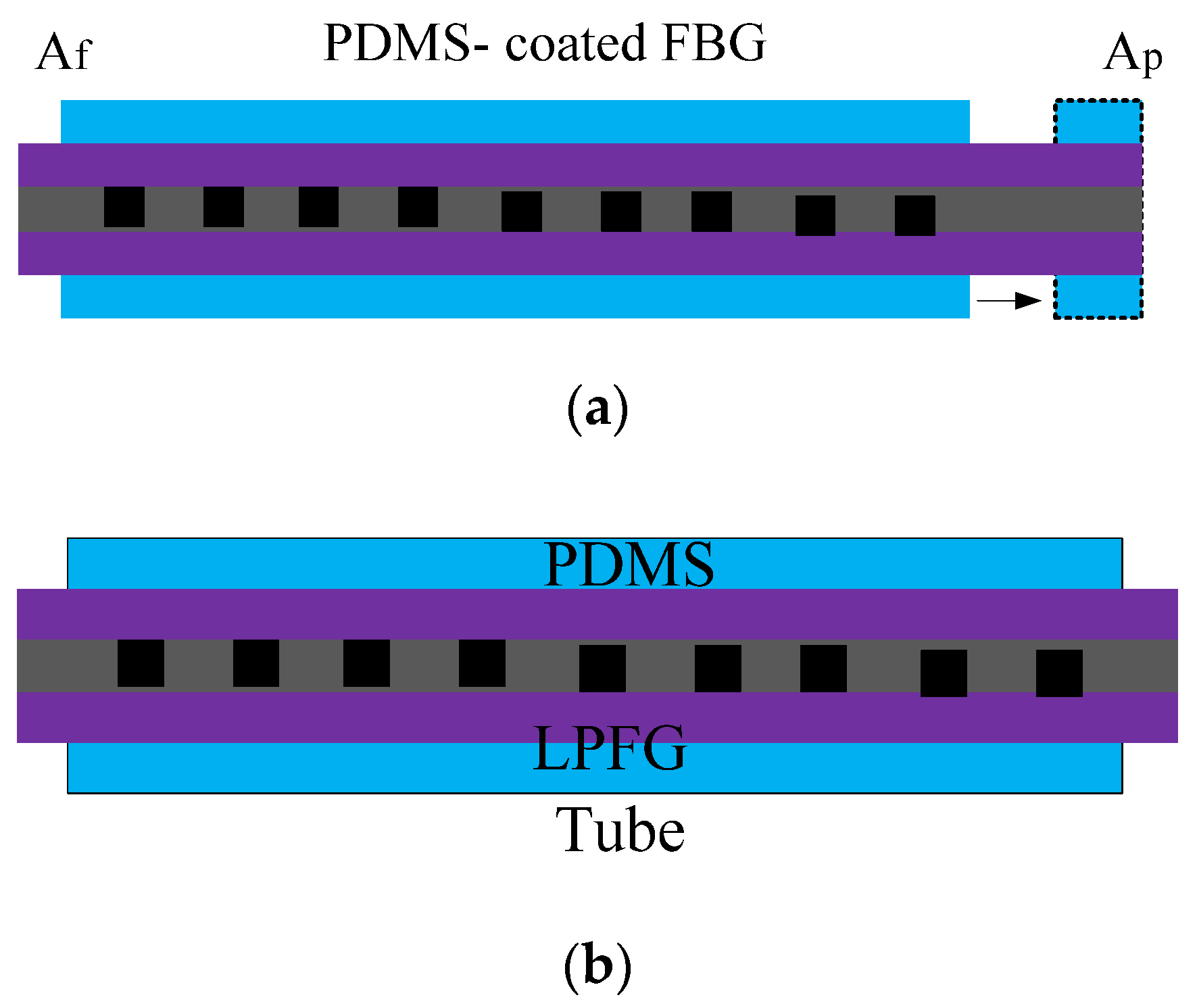
2.2. A Variety of Structures Based on FBG/LPFG (Long-Period Fiber Grating)
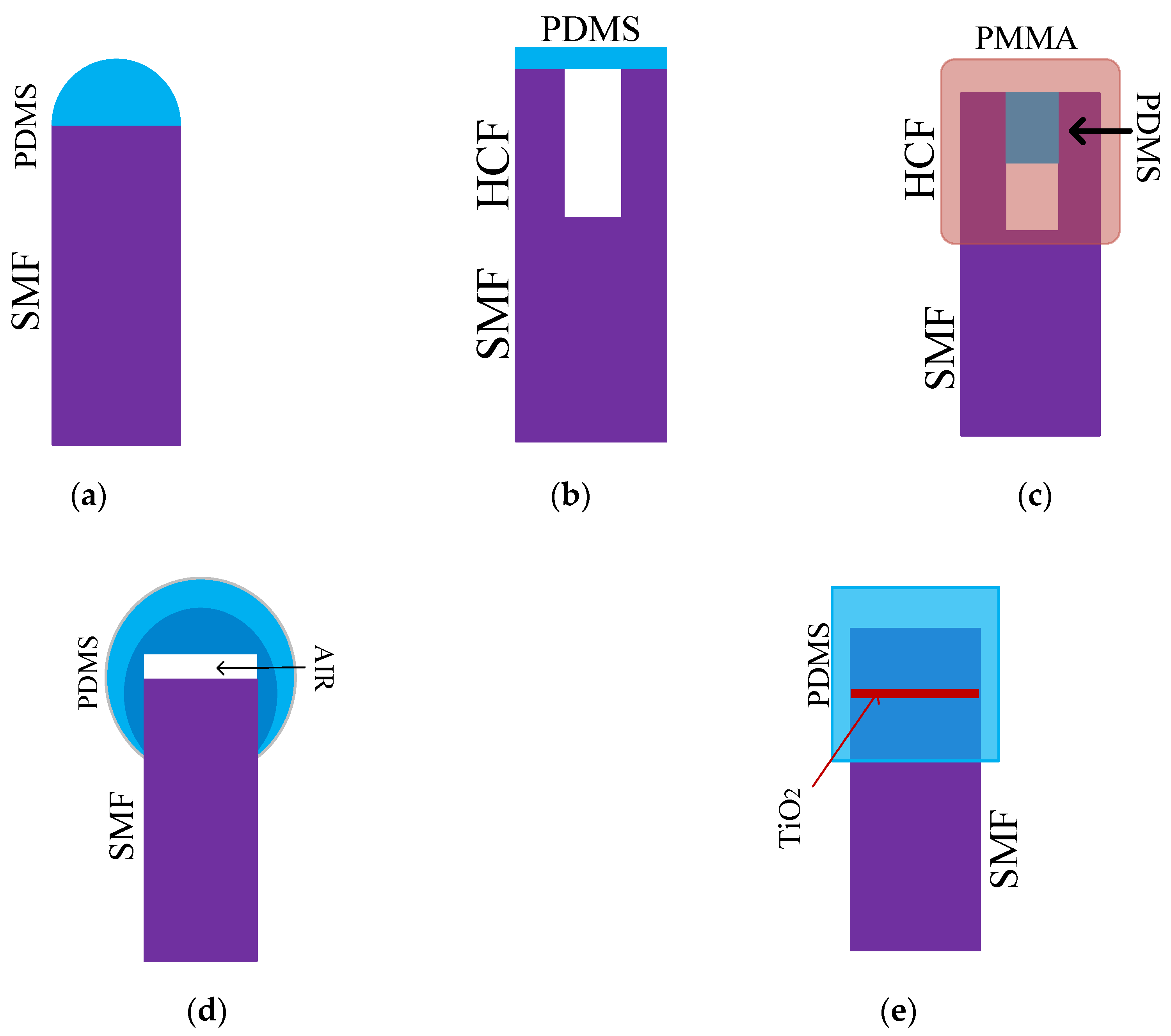
2.3. A Variety of Structures Based on F-P
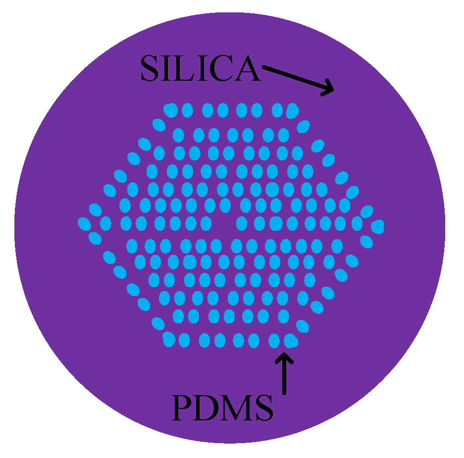
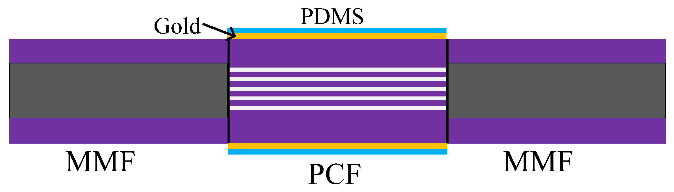
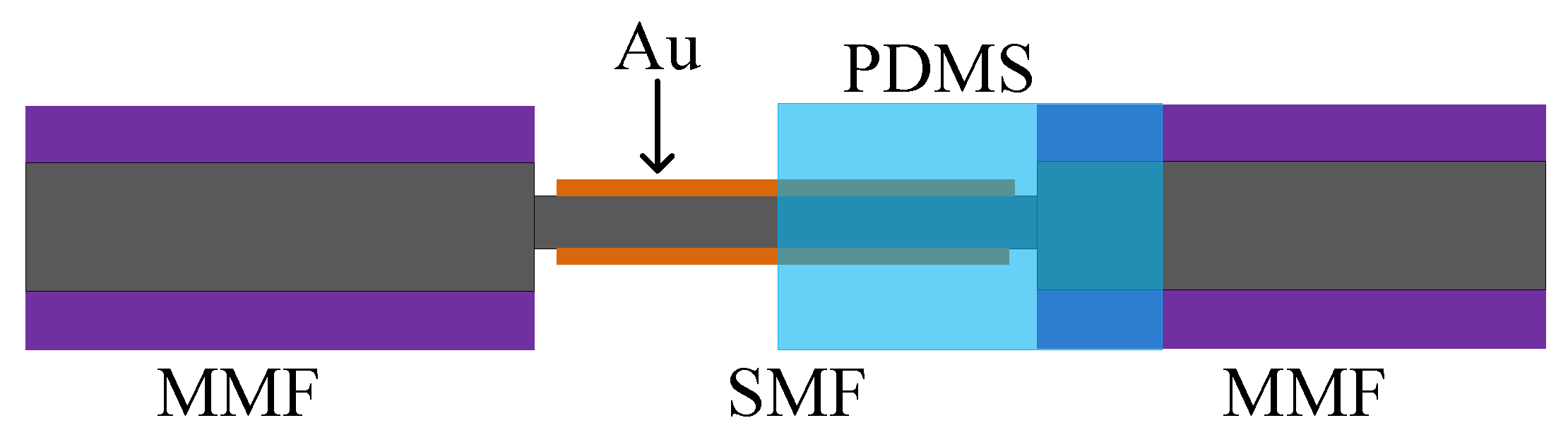
2.4. A Variety of Structures Based on SPR (Surface Plasmon Resonance)
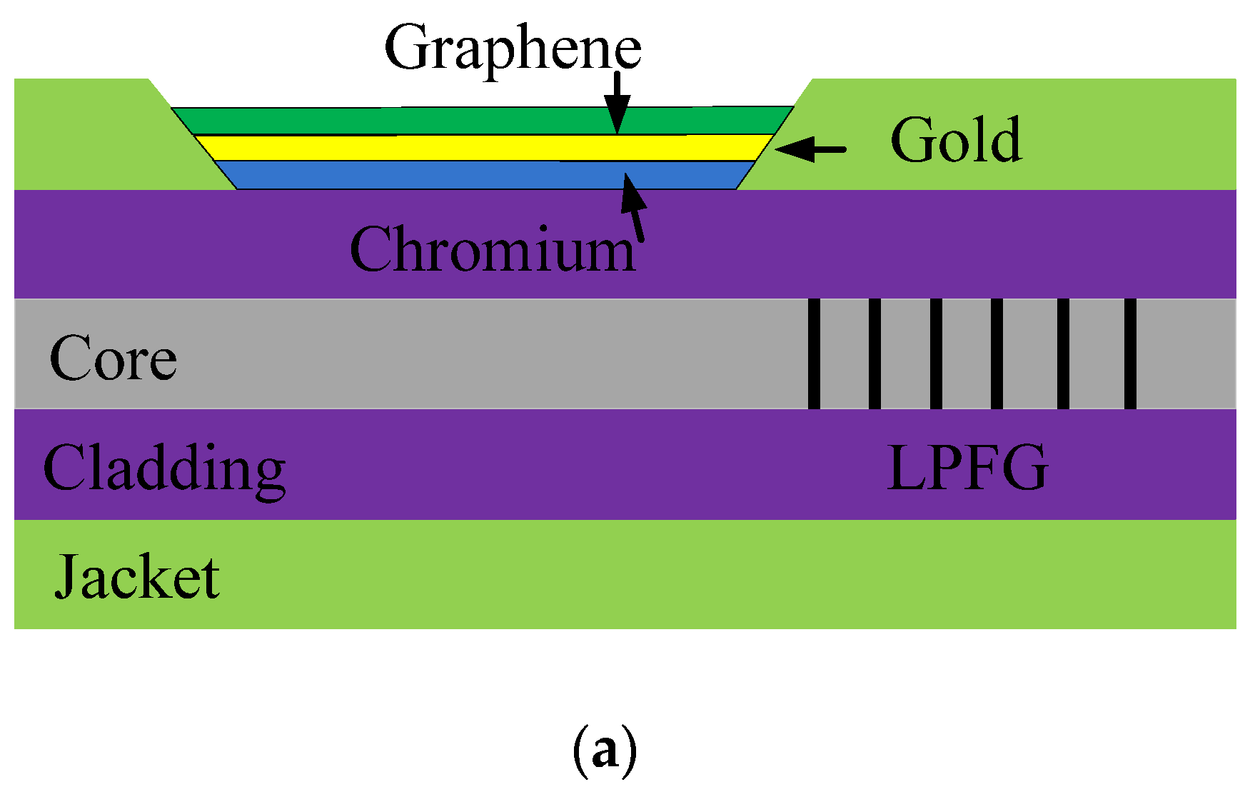
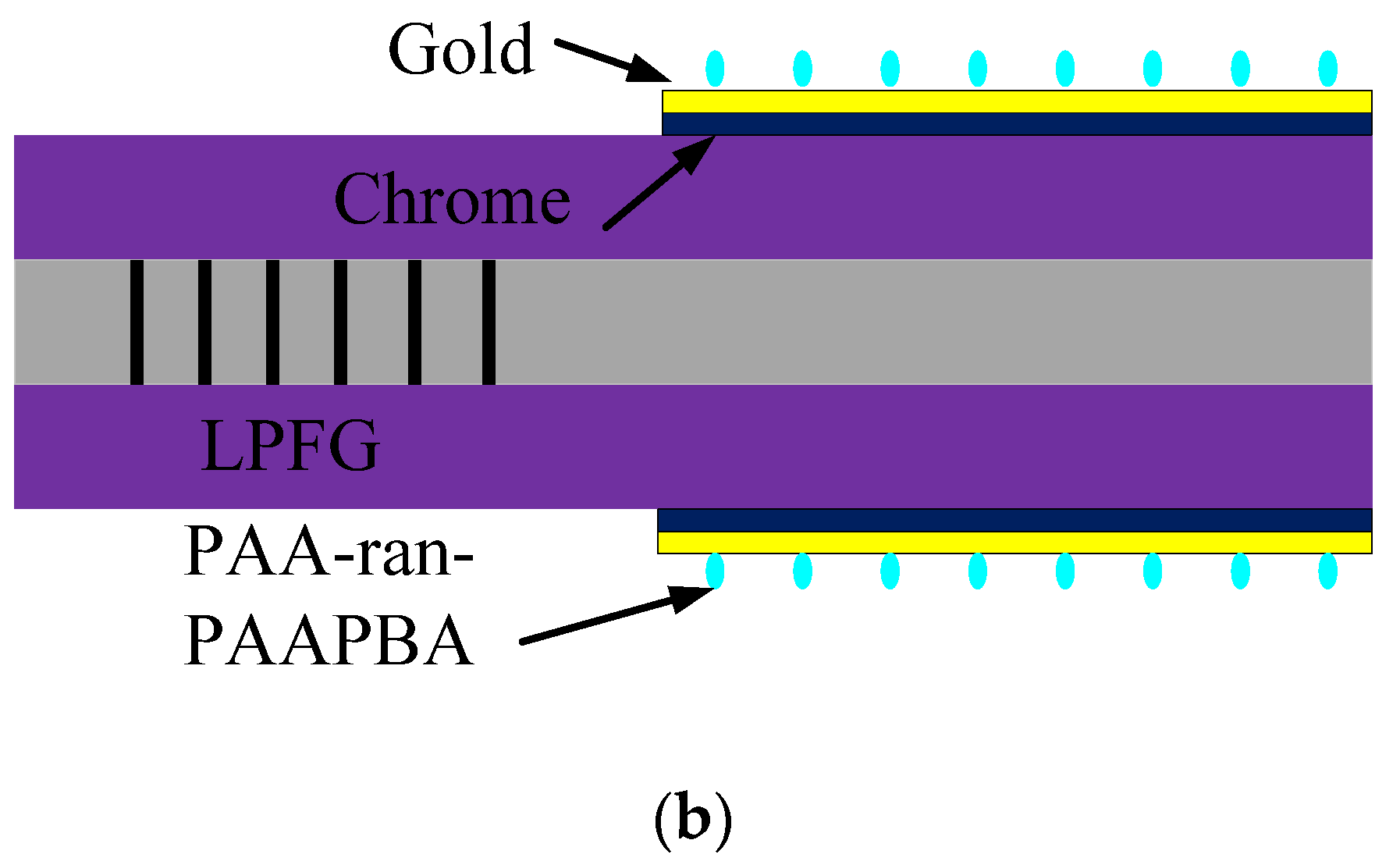
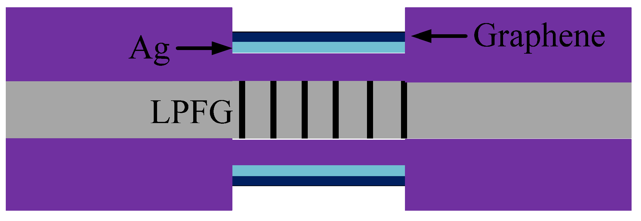
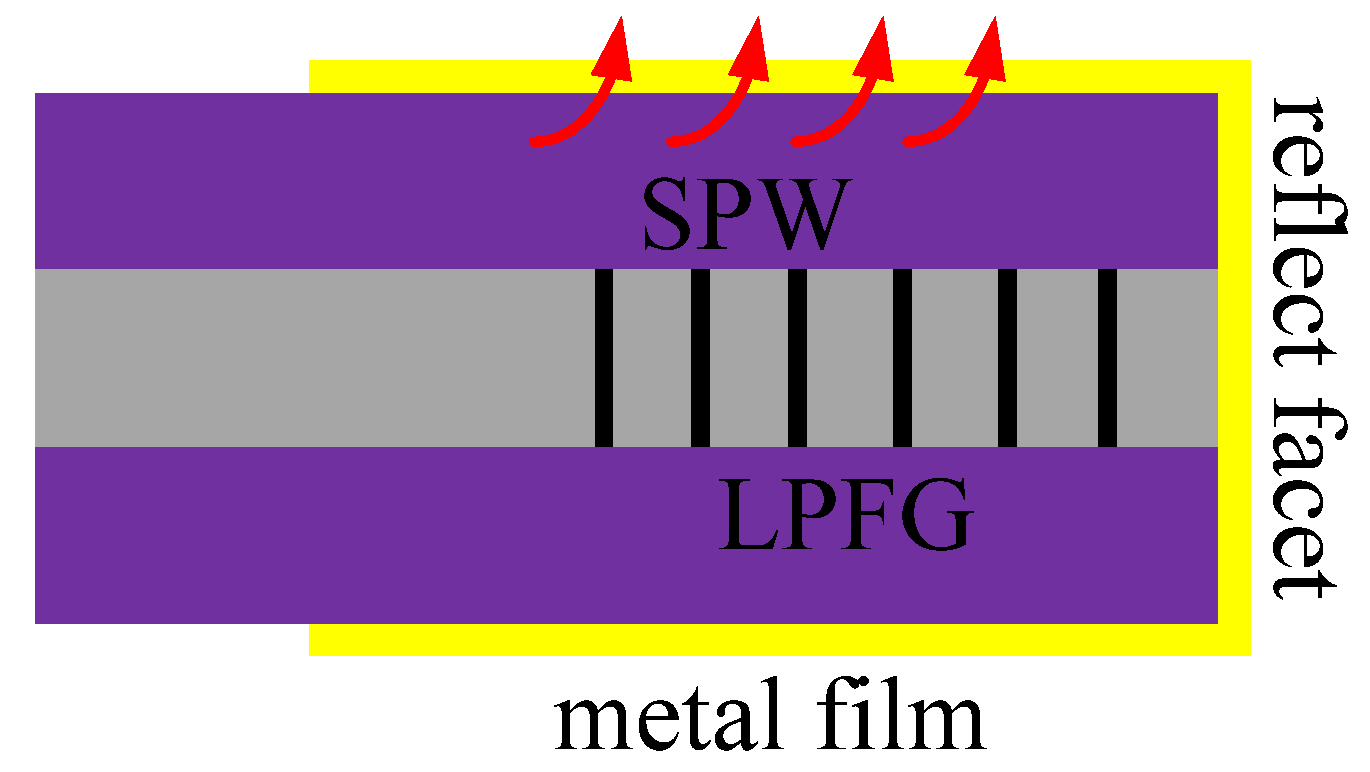
2.5. SPR Sensors Based on LPFG
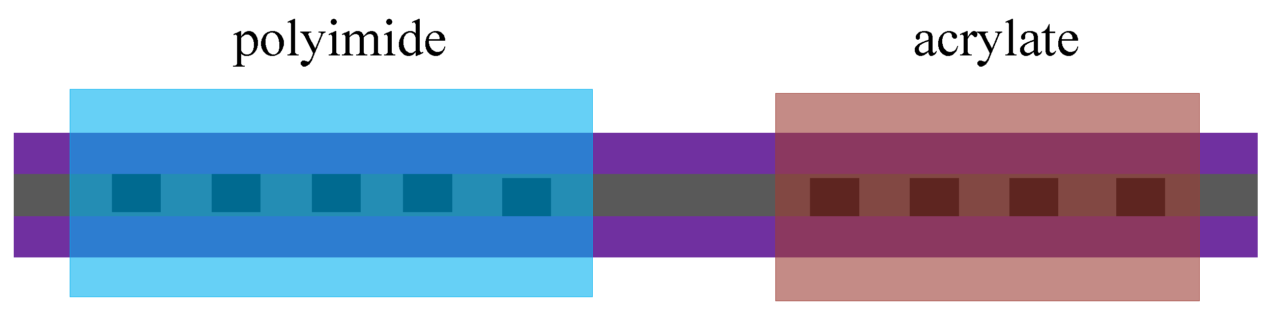
3. Sensors Coated with Polyimide, Acrylate, and Materials for Cryogenic Applications
4. Sensors Coated with UV-Sensitive Materials
5. Sensors Coated with Graphene, Metal Ions, and Others
6. Conclusions
Author Contributions
Funding
Conflicts of Interest
References
- Thangawng, A.L.; Ruoff, R.S.; Swartz, M.A.; Glucksberg, M.R. An ultra-thin PDMS membrane as a bio/micro–nano interface: Fabrication and characterization. Biomed. Microdevices 2007, 9, 587–595. [Google Scholar] [CrossRef] [PubMed]
- Zhou, J.; Ellis, A.V.; Voelcker, N.H. Recent developments in PDMS surface modification for microfluidic devices. Electrophoresis 2010, 31, 2–16. [Google Scholar] [CrossRef] [PubMed]
- Berthier, E.; Young, E.W.K.; Beebe, D. Engineers are from PDMS-land, Biologists are from Polystyrenia. Lab Chip 2012, 12, 1224. [Google Scholar] [CrossRef] [PubMed]
- Li, L.; Xiao, Z.; Tan, S.; Pu, L.; Zhang, Z. Composite PDMS membrane with high flux for the separation of organics from water by pervaporation. J. Membr. Sci. 2004, 243, 177–187. [Google Scholar] [CrossRef]
- Odom, T.W.; Thalladi, V.R.; Love, A.J.C.; Whitesides, G.M. Generation of 30−50 nm Structures Using Easily Fabricated, Composite PDMS Masks. J. Am. Chem. Soc. 2002, 124, 12112–12113. [Google Scholar] [CrossRef]
- Camou, S.; Fujita, H.; Fujii, T. PDMS 2D optical lens integrated with microfluidic channels: Principle and characterization. Lab Chip 2003, 3, 40–45. [Google Scholar] [CrossRef]
- Wu, P.; Field, R.; England, R.; Brisdon, B. A fundamental study of organofunctionalised PDMS membranes for the pervaporative recovery of phenolic compounds from aqueous streams. J. Membr. Sci. 2001, 190, 147–157. [Google Scholar] [CrossRef]
- Bhagat, A.A.S.; Jothimuthu, P.; Papautsky, I. Photodefinable polydimethylsiloxane (PDMS) for rapid lab-on-a-chip prototyping. Lab Chip 2007, 7, 1192–1197. [Google Scholar] [CrossRef]
- Shiku, H.; Saito, T.; Wu, C.-C.; Yasukawa, T.; Yokoo, M.; Abé, H.; Matsue, T.; Yamada, H. Oxygen Permeability of Surface-modified Poly(dimethylsiloxane) Characterized by Scanning Electrochemical Microscopy. Chem. Lett. 2006, 35, 234–235. [Google Scholar] [CrossRef]
- Chaffin, K.; Wilson, C.L.; Himes, A.K.; Dawson, J.W.; Haddad, T.D.; Buckalew, A.J.; Miller, J.P.; Untereker, D.F.; Simha, N.K. Abrasion and fatigue resistance of PDMS containing multiblock polyurethanes after accelerated water exposure at elevated temperature. Biomaterials 2013, 34, 8030–8041. [Google Scholar] [CrossRef]
- Liu, H.-S.; Pan, B.-C.; Liou, G.-S. Highly transparent AgNW/PDMS stretchable electrodes for elastomeric electrochromic devices. Nanoscale 2017, 9, 2633–2639. [Google Scholar] [CrossRef] [PubMed]
- Francioso, L.; De Pascali, C.; Bartali, R.; Morganti, E.; Lorenzelli, L.; Siciliano, P.A.; Laidani, N. PDMS/Kapton Interface Plasma Treatment Effects on the Polymeric Package for a Wearable Thermoelectric Generator. ACS Appl. Mater. Interfaces 2013, 5, 6586–6590. [Google Scholar] [CrossRef] [PubMed]
- Tai, Y.-L.; Yang, Z.-G. Flexible pressure sensing film based on ultra-sensitive SWCNT/PDMS spheres for monitoring human pulse signals. J. Mater. Chem. B 2015, 3, 5436–5441. [Google Scholar] [CrossRef] [PubMed]
- Chang-Yen, D.; Eich, R.; Gale, B.K. A monolithic PDMS waveguide system fabricated using soft-lithography techniques. J. Light. Technol. 2005, 23, 2088–2093. [Google Scholar] [CrossRef]
- Kopetz, S.; Cai, D.; Rabe, E.; Neyer, A. PDMS-based optical waveguide layer for integration in electrical–optical circuit boards. AEU—Int. J. Electron. Commun. 2007, 61, 163–167. [Google Scholar] [CrossRef]
- Valouch, S.; Sieber, H.; Kettlitz, S.; Eschenbaum, C.; Hollenbach, U.; Lemmer, U. Direct fabrication of PDMS waveguides via low-cost DUV irradiation for optical sensing. Opt. Express 2012, 20, 28855–28861. [Google Scholar] [CrossRef]
- Martincek, I.; Pudis, D.; Gaso, P. Fabrication and Optical Characterization of Strain Variable PDMS Biconical Optical Fiber Taper. IEEE Photonics Technol. Lett. 2013, 25, 2066–2069. [Google Scholar] [CrossRef]
- Martincek, I.; Pudis, D.; Chalupová, M. Technology for the Preparation of PDMS Optical Fibers and Some Fiber Structures. IEEE Photonics Technol. Lett. 2014, 26, 1446–1449. [Google Scholar] [CrossRef]
- Sidek, O.; Bin Afzal, M.H. A review paper on fiber-optic sensors and application of PDMS materials for enhanced performance. In Proceedings of the 2011 IEEE Symposium on Business, Engineering and Industrial Applications (ISBEIA), Langkawi, Malaysia, 25–28 September 2011; pp. 458–463. [Google Scholar]
- Yang, W.; Li, C.; Wang, M.; Yu, X.; Fan, J.; Xiong, Y.; Yang, Y.; Li, L. The Polydimethylsiloxane Coated Fiber Optic for All Fiber Temperature Sensing Based on the Multi-Thin-Multi Fiber Structure. IEEE Sens. J. 2020, 1. [Google Scholar] [CrossRef]
- Romano, I.H.; Monzón-Hernández, D.; Moreno-Hernández, C.; Moreno-Hernández, D.; Villatoro, J. Highly Sensitive Temperature Sensor Based on a Polymer-Coated Microfiber Interferometer. IEEE Photonics Technol. Lett. 2015, 27, 2591–2594. [Google Scholar] [CrossRef]
- Kacik, D.; Tatar, P.; Turek, I. Locally pressed etched optical fiber with PDMS coating for a sensor application. Optik. 2016, 127, 5631–5635. [Google Scholar] [CrossRef]
- Gong, J.; Shen, C.; Xiao, Y.; Liu, S.; Zhang, C.; Ding, Z.; Deng, H.; Yu, J.; Hou, Y.; Fang, J.; et al. Optical fiber temperature sensor based on Mach-Zehnder interferometer coated with a film of PDMS. In Proceedings of the 2019 18th International Conference on Optical Communications and Networks (ICOCN), Huangshan, China, 5–8 August 2019. [Google Scholar]
- Yang, R.; Yu, Y.-S.; Zhu, C.-C.; Xue, Y.; Chen, C.; Zhang, X.-Y.; Zhang, B.-L.; Sun, H.-B. PDMS-Coated S-Tapered Fiber for Highly Sensitive Measurements of Transverse Load and Temperature. IEEE Sens. J. 2015, 15, 3429–3435. [Google Scholar] [CrossRef]
- Martincek, I.; Kacik, D. A PDMS microfiber Mach-Zehnder interferometer and determination of nanometer displacements. Opt. Fiber Technol. 2018, 40, 13–17. [Google Scholar] [CrossRef]
- Liu, Z.; Xiao, H.; Liao, M.; Han, X.; Chen, W.; Zhao, T.; Jia, H.; Yang, J.; Tian, Y. PDMS-Assisted Microfiber M-Z Interferometer with a Knot Resonator for Temperature Sensing. IEEE Photonics Technol. Lett. 2019, 31, 337–340. [Google Scholar] [CrossRef]
- Fan, R.; Yang, J.; Li, J.; Meng, F. Temperature measurement using a microfiber knot ring encapsulated in PDMS. Phys. Scr. 2019, 94, 125706. [Google Scholar] [CrossRef]
- He, C.; Fang, J.; Zhang, Y.; Yang, Y.; Yu, J.; Zhang, J.; Guan, H.; Qiu, W.; Wu, P.; Dong, J.; et al. High performance all-fiber temperature sensor based on coreless side-polished fiber wrapped with polydimethylsiloxane. Opt. Express 2018, 26, 9686–9699. [Google Scholar] [CrossRef] [PubMed]
- Cai, L.; Liu, Y.; Hu, S.; Liu, Q. Optical fiber temperature sensor based on modal interference in multimode fiber lengthened by a short segment of polydimethylsiloxane. Microw. Opt. Technol. Lett. 2019, 61, 1656–1660. [Google Scholar] [CrossRef]
- Gao, H.; Hu, H.-F.; Zhao, Y.; Li, J.; Lei, M.; Zhang, Y. Highly-sensitive optical fiber temperature sensors based on PDMS/silica hybrid fiber structures. Sens. Actuators A Phys. 2018, 284, 22–27. [Google Scholar] [CrossRef]
- Martinez-Gaytan, A.; Soto-Olmos, J.; Oropeza-Ramos, L.; Hernández-Cordero, J. Fabrication Process for PDMS Polymer/Silica Long-Period Fiber Grating Sensors. IEEE Photonics Technol. Lett. 2015, 27, 2150–2153. [Google Scholar] [CrossRef]
- Park, C.-S.; Joo, K.-I.; Kang, S.-W.; Kim, H.-R. A PDMS-Coated Optical Fiber Bragg Grating Sensor for Enhancing Temperature Sensitivity. J. Opt. Soc. Korea 2011, 15, 329–334. [Google Scholar] [CrossRef]
- Wang, Q.; Du, C.; Zhang, J.; Lv, R.; Zhao, Y. Sensitivity-enhanced temperature sensor based on PDMS-coated long period fiber grating. Opt. Commun. 2016, 377, 89–93. [Google Scholar] [CrossRef]
- Joo, K.-I.; Han, Y.; Park, C.-S.; Lee, Y.W.; Kong, S.H.; Kang, S.-W.; Kim, H.-R. Optical sensing of solvents using selective tensile effects of a PDMS-coated Fiber Bragg Grating. In Proceedings of the IEEE Sensors 2010 Conference, Kona, HI, USA, 1–4 November 2010; pp. 1645–1648. [Google Scholar] [CrossRef]
- Zhang, X.-Y.; Yu, Y.-S.; Zhu, C.-C.; Chen, C.; Yang, R.; Xue, Y.; Chen, Q.-D.; Sun, H.-B. Miniature End-Capped Fiber Sensor for Refractive Index and Temperature Measurement. IEEE Photonics Technol. Lett. 2013, 26, 7–10. [Google Scholar] [CrossRef]
- Ning, X.; Yang, J.; Zhao, C.L.; Chan, C.C. PDMS-coated fiber volatile organic compounds sensors. Appl. Opt. 2016, 55, 3543–3548. [Google Scholar] [CrossRef] [PubMed]
- Kong, L.-X.; Zhang, Y.-X.; Zhang, Y.-X.; Zhang, Y.-S.; Yu, L.; Wang, S.; Geng, P.-C.; Yan, T.-Y. High-sensitivity and fast-response fiber-optic micro-thermometer based on a plano-concave Fabry-Pérot cavity filled with PDMS. Sens. Actuators A Phys. 2018, 281, 236–242. [Google Scholar] [CrossRef]
- Kacik, D.; Martincek, I. Toluene optical fibre sensor based on air microcavity in PDMS. Opt. Fiber Technol. 2017, 34, 70–73. [Google Scholar] [CrossRef]
- Romano, I.H.; Cruz-Garcia, M.A.; Moreno-Hernández, C.; Monzón-Hernández, D.; López-Figueroa, E.O.; Paredes-Gallardo, O.E.; Torres-Cisneros, M.; Villatoro, J. Optical fiber temperature sensor based on a microcavity with polymer overlay. Opt. Express 2016, 24, 5654. [Google Scholar] [CrossRef]
- Mukhopadhyay, R. When PDMS isn’t the best. Anal. Chem. 2007, 79, 3248–3253. [Google Scholar] [CrossRef]
- Markos, C.; Vlachos, K.; Kakarantzas, G. Bending loss and thermo-optic effect of a hybrid PDMS/silica photonic crystal fiber. Opt. Express 2010, 18, 24344–24351. [Google Scholar] [CrossRef]
- Wang, Y.; Huang, Q.; Zhu, W.; Yang, M.; Lewis, E. Novel optical fiber SPR temperature sensor based on MMF-PCF-MMF structure and gold-PDMS film. Opt. Express 2018, 26, 1910–1917. [Google Scholar] [CrossRef]
- Velázquez-González, J.S.; Monzón-Hernández, D.; Moreno-Hernández, D.; Martínez-Piñón, F.; Romano, I.H. Simultaneous measurement of refractive index and temperature using a SPR-based fiber optic sensor. Sens. Actuators B Chem. 2017, 242, 912–920. [Google Scholar] [CrossRef]
- Huang, Q.; Wang, Y.; Zhu, W.; Lai, T.; Peng, J.; Lyu, D.; Guo, D.; Yuan, Y.; Lewis, E.; Yang, M. Graphene–Gold–Au@Ag NPs-PDMS Films Coated Fiber Optic for Refractive Index and Temperature Sensing. IEEE Photon. Technol. Lett. 2019, 31, 1205–1208. [Google Scholar] [CrossRef]
- Coelho, L.; Queirós, R.B.; Santos, J.L.; Martins, M.C.L.; Viegas, D.; Jorge, P.A.S. DNA-Aptamer optical biosensors based on a LPG-SPR optical fiber platform for point-of-care diagnostic. In Proceedings of the Plasmonics in Biology and Medicine XI. International Society for Optics and Photonics, San Francisco, CA, USA, 3 March 2014; Volume 8957, p. 89570K. [Google Scholar]
- Gu, Z.; Lan, J.; Gao, K. Characteristics of plasmon coupling mode in SPR based LPFG. Opt. Quantum Electron. 2016, 48, 171. [Google Scholar] [CrossRef]
- Hu, H.-F.; Deng, Z.-Q.; Zhao, Y.; Li, J.; Wang, Q. Sensing Properties of Long Period Fiber Grating Coated by Silver Film. IEEE Photon. Technol. Lett. 2015, 27, 46–49. [Google Scholar] [CrossRef]
- Wang, W.; Wu, W.; Huang, J.; Tian, X.; Fei, X. Modeling of a long-period fiber-optic grating-assisted surface plasmon resonance refractive index sensor. In Proceedings of the Advanced Sensor Systems and Applications VII, Beijing, China, 4 November 2016. [Google Scholar]
- Lu, B.; Sun, Y.; Lai, X.; Pu, Z.; Yu, H.; Xu, K.; Li, D. Side-polished fiber SPR sensor with temperature self-compensation for continuous glucose monitoring. In Proceedings of the 2016 IEEE 29th International Conference on Micro Electro Mechanical Systems (MEMS), Shanghai, China, 24–28 January 2016. [Google Scholar]
- Li, D.; Wu, P.; Zhu, R.; Yang, J.; Yu, H.; Xu, K. Implantable fiber-optic SPR sensor modified with LPFG and PAA-ran-PAAPBA for continuous glucose monitoring. In Proceedings of the IEEE Sensors 2012, Taipei, Taiwan, 28–31 October 2012. [Google Scholar] [CrossRef]
- Wei, W.; Nong, J.; Zhang, G.; Tang, L.; Jiang, X.; Chen, N.; Luo, S.; Lan, G.; Zhu, Y. Graphene-Based Long-Period Fiber Grating Surface Plasmon Resonance Sensor for High-Sensitivity Gas Sensing. Sensors 2016, 17, 2. [Google Scholar] [CrossRef]
- Zhang, G.; Wang, C.; Zhao, M.; Cao, B. Optical resonance analysis of reflected long period fiber gratings with metal film overlay. In Proceedings of the ASIA-PACIFIC Optical Communications, Hangzhou, China, 26–30 October 2008; p. 713438. [Google Scholar]
- Zhao, M.; Zhang, G.; Ma, D. Single-ended long period fiber grating refractive index sensor based on metal-coated surface plasma resonance. In Proceedings of the 2008 International Conference on Optical Instruments and Technology: Advanced Sensor Technologies and Applications, Beijing, China, 16–19 November 2008; p. 7157. [Google Scholar]
- Scurti, F.; McGarrahan, J.; Schwartz, J. Effects of metallic coatings on the thermal sensitivity of optical fiber sensors at cryogenic temperatures. Opt. Mater. Express 2017, 7, 1754–1766. [Google Scholar] [CrossRef]
- Marx, B.; Warstat, K.; Röhrich, A.; Hill, W. Amplitude-Based BOTDR Sensing at Cryogenic Temperatures using Polyimide Coated Fibers. In Proceedings of the 26th International Conference on Optical Fiber Sensors, Lausanne, Switzerland, 24–28 September 2018; p. TuE24. [Google Scholar]
- Gupta, S.; Mizunami, T.; Yamao, T.; Shimomura, T. Fiber Bragg grating cryogenic temperature sensors. Appl. Opt. 1996, 35, 5202–5205. [Google Scholar] [CrossRef]
- Sampath, U.; Kim, D.; Kim, H.; Song, M. Polymer-coated FBG sensor for simultaneous temperature and strain monitoring in composite materials under cryogenic conditions. Appl. Opt. 2018, 57, 492–497. [Google Scholar] [CrossRef]
- Yamada, H.; Tanaka, Y.; Ogata, M.; Mizuno, K.; Nagashima, K.; Okumura, S.; Terada, Y. Measurement and improvement of characteristics using optical fiber temperature sensors at cryogenic temperatures. Phys. C Supercond. Appl. 2011, 471, 1570–1575. [Google Scholar] [CrossRef]
- Mahar, S.; Geng, J.; Schultz, J.; Minervini, J.V.; Jiang, S.; Titus, P.; Takayasu, M.; Gung, C.-Y.; Tian, W.; Chavez-Pirson, A. Real-time simultaneous temperature and strain measurements at cryogenic temperatures in an optical fiber. In Proceedings of the Optical Engineering + Applications, San Diego, CA, USA, 10–14 August 2008. [Google Scholar] [CrossRef]
- Li, Y.; Yang, K.; Li, X. Temperature sensing characteristics of metal coated FBG during dynamic cooling process. Opt. Fiber Technol. 2018, 45, 368–375. [Google Scholar] [CrossRef]
- Lu, X.; Soto, M.A.; Thevenaz, L. Impact of the Fiber Coating on the Temperature Response of Distributed Optical Fiber Sensors at Cryogenic Ranges. J. Light. Technol. 2017, 36, 961–967. [Google Scholar] [CrossRef]
- Scurti, F.; Sathyamurthy, S.; Rupich, M.; Schwartz, J. Self-monitoring ‘SMART’(RE) Ba2Cu3O7—X conductor via integrated optical fibers. Supercond. Sci. Technol. 2017, 30, 114002. [Google Scholar] [CrossRef]
- Liu, Y.; Badcock, R.A.; Fang, X.; Fang, J.; Yan, X.; Zhou, W. Selecting of FBG Coatings for Quench Detection in HTS Coils. IEEE Trans. Appl. Supercond. 2018, 28, 1–5. [Google Scholar] [CrossRef]
- Jiang, J.; Zhong, L.; Duan, X.; Song, M.; Li, L.; Wu, Z.; Li, Z.; Huang, Z.; Jin, Z.; Yao, L.; et al. Bend Limitation of a Polyimide-Coated Optical Fiber at Cryogenic Temperature of 77 K. IEEE Trans. Appl. Supercond. 2018, 29, 8400305. [Google Scholar] [CrossRef]
- Brannon, J.H.; Lankard, J.R.; Baise, A.I.; Burns, F.; Kaufman, J. Excimer laser etching of polyimide. J. Appl. Phys. 1985, 58, 2036–2043. [Google Scholar] [CrossRef]
- Kanno, M.; Kawakami, H.; Nagaoka, S.; Kubota, S. Biocompatibility of fluorinated polyimide. J. Biomed. Mater. Res. 2002, 60, 53–60. [Google Scholar] [CrossRef]
- Yoshida, M.; Lal, M.; Kumar, N.D.; Prasad, P.N. TiO2 nano-particle-dispersed polyimide composite optical waveguide materials through reverse micelles. J. Mater. Sci. 1997, 32, 4047–4051. [Google Scholar] [CrossRef]
- Huang, J.-C.; Zhu, Z.-K.; Ma, X.-D.; Qian, X.-F.; Yin, J. Preparation and properties of montmorillonite/organo-soluble polyimide hybrid materials prepared by a one-step approach. J. Mater. Sci. 2001, 36, 871–877. [Google Scholar] [CrossRef]
- Liu, H.; Li, Y.; Wang, T.; Wang, Q. In situ synthesis and thermal, tribological properties of thermosetting polyimide/graphene oxide nanocomposites. J. Mater. Sci. 2012, 47, 1867–1874. [Google Scholar] [CrossRef]
- Newaz, G.M.; Mian, A.; Sultana, T.; Mahmood, T.; Georgiev, D.; Auner, G.; Witte, R.; Herfurth, H. A comparison between glass/polyimide and titanium/polyimide microjoint performances in cerebrospinal fluid. J. Biomed. Mater. Res. Part A 2006, 79, 159–165. [Google Scholar] [CrossRef]
- Lagorce, L.; Allen, M. Magnetic and mechanical properties of micromachined strontium ferrite/polyimide composites. J. Microelectromechanical Syst. 1997, 6, 307–312. [Google Scholar] [CrossRef]
- Nicholson, L.M.; Whitley, K.S.; Gates, T.S.; Hinkley, J.A. Influence of molecular weight on the mechanical performance of a thermoplastic glassy polyimide. J. Mater. Sci. 2000, 35, 6111–6121. [Google Scholar] [CrossRef]
- Ramos, M. Theoretical study of metal–polyimide interfacial properties. Vacuum 2002, 64, 255–260. [Google Scholar] [CrossRef]
- Al-Kandary, S.; Ali, A.A.M.; Ahmad, Z. New polyimide-silica nano-composites from the sol-gel process using organically-modified silica network structure. J. Mater. Sci. 2006, 41, 2907–2914. [Google Scholar] [CrossRef]
- Laarossi, I.; Quintela, M.; López-Higuera, J.M. Comparative Experimental Study of a High-Temperature Raman-Based Distributed Optical Fiber Sensor with Different Special Fibers. Sensors 2019, 19, 574. [Google Scholar] [CrossRef]
- Satori, K.; Fukuchi, K.; Kurosawa, Y.; Hongo, A.; Takeda, N. Polyimide-coated small-diameter optical fiber sensors for embedding in composite laminate structures. In Proceedings of the SPIE’S 8th Annual International Symposium on Smart Structures and Materials, Newport Beach, CA, USA, 5–8 March 2001; Volume 4328, pp. 285–295. [Google Scholar]
- Men, L.; Lu, P.; Chen, Q. A multiplexed fiber Bragg grating sensor for simultaneous salinity and temperature measurement. J. Appl. Phys. 2008, 103, 33–39. [Google Scholar] [CrossRef]
- Wang, L.; Fang, N.; Huang, Z. Polyimide-Coated Fiber Bragg Grating Sensors for Humidity Measurements. In High Performance Polymers-Polyimides Based-from Chemistry to Applications; IntechOpen: London, UK, 2012. [Google Scholar] [CrossRef]
- Berruti, G.; Consales, M.; Giordano, M.; Sansone, L.; Petagna, P.; Buontempo, S.; Breglio, G.; Cusano, A. Radiation hard humidity sensors for high energy physics applications using polyimide-coated fiber Bragg gratings sensors. Sens. Actuators B Chem. 2013, 177, 94–102. [Google Scholar] [CrossRef]
- Zhong, N.; Liao, Q.; Zhu, X.; Zhao, M. Fiber Bragg Grating with Polyimide–Silica Hybrid Membrane for Accurately Monitoring Cell Growth and Temperature in a Photobioreactor. Anal. Chem. 2014, 86, 9278–9285. [Google Scholar] [CrossRef]
- Zhang, L.; Liu, Y.; Gao, X.; Xia, Z. High temperature strain sensor based on a fiber Bragg grating and rhombus metal structure. Appl. Opt. 2015, 54, E109–E112. [Google Scholar] [CrossRef]
- Wang, W.; Sun, T.; Peng, J.; Dai, J.; Yang, M. Humidity Sensor Based on Fiber Bragg Grating Coated with Different Pore-Foaming Agent Doped Polyimides. IEEE Photon. Technol. Lett. 2017, 29, 1963–1966. [Google Scholar] [CrossRef]
- Sun, T.; Wang, W.; Peng, J.; Qu, Y.; Dai, J.; Yang, M. Effect of Different Inorganics on Polyimide-Based Bragg Grating Humidity Sensor. IEEE Sens. J. 2019, 19, 2016–2022. [Google Scholar] [CrossRef]
- Wu, C.; Guan, B.-O.; Lu, C.; Tam, H.Y. Salinity sensor based on polyimide-coated photonic crystal fiber. Opt. Express 2011, 19, 20003–20008. [Google Scholar] [CrossRef] [PubMed]
- Zhang, X.; Peng, W. Temperature-independent fiber salinity sensor based on Fabry-Perot interference. Opt. Express 2015, 23, 10353–10358. [Google Scholar] [CrossRef] [PubMed]
- Peng, Z.; Wang, L.; Yan, H. Research on high-temperature sensing characteristics based on modular interference of single-mode multimode single-mode fiber. SPIE/COS Photonics Asia 2016, 10025, 1002519. [Google Scholar] [CrossRef]
- Wang, S.; Liu, T.; Wang, X.; Liao, Y.; Wang, J.; Wen, J. Hybrid structure Mach-Zehnder interferometer based on silica and fluorinated polyimide microfibers for temperature or salinity sensing in seawater. Measurement 2019, 135, 527–536. [Google Scholar] [CrossRef]
- Wang, Q.K.; Huang, B.Q.; Wei, X.F.; Shen, H.C. Study on Shrinkage of Cured Volume for UV-Curing Coatings. Appl. Mech. Mater. 2015, 731, 588–592. [Google Scholar] [CrossRef]
- Kim, K.-R.; Chang, S.; Oh, K. Refractive microlens on fiber using UV-curable fluorinated acrylate polymer by surface-tension. IEEE Photon. Technol. Lett. 2003, 15, 1100–1102. [Google Scholar] [CrossRef]
- Tan, X.L.; Geng, Y.F.; Li, X.J.; Deng, Y.-L.; Yin, Z.; Gao, R. UV-Curable Polymer Microhemisphere-Based Fiber-Optic Fabry–Perot Interferometer for Simultaneous Measurement of Refractive Index and Temperature. IEEE Photonics J. 2014, 6, 1–8. [Google Scholar] [CrossRef]
- Sun, B.; Wang, Y.; Qu, J.; Liao, C.; Yin, G.; He, J.; Zhou, J.; Tang, J.; Liu, S.; Li, Z.; et al. Simultaneous measurement of pressure and temperature by employing Fabry-Perot interferometer based on pendant polymer droplet. Opt. Express 2015, 23, 1906–1911. [Google Scholar] [CrossRef]
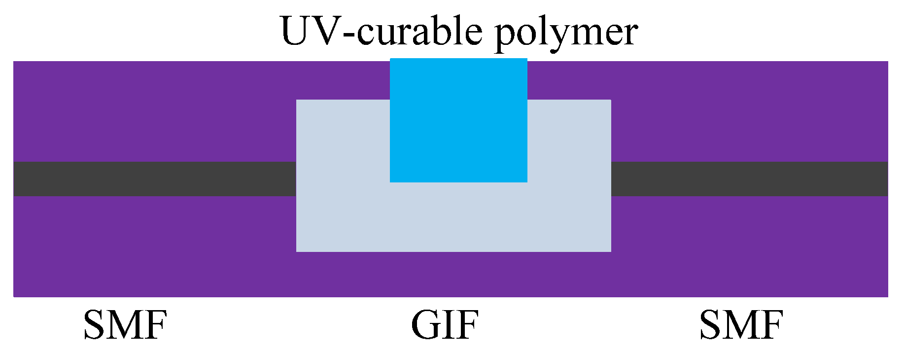
- Zhang, F.; Xu, X.; He, J.; Du, B.; Wang, Y. Highly sensitive temperature sensor based on a polymer-infiltrated Mach-Zehnder interferometer created in graded index fiber. Opt. Lett. 2019, 44, 2466–2469. [Google Scholar] [CrossRef]
- Wang, H.; Yang, A. Temperature sensing property of hollow-core photonic bandgap fiber filled with CdSe/ZnS quantum dots in an UV curing adhesive. Opt. Fiber Technol. 2017, 38, 104–107. [Google Scholar] [CrossRef]
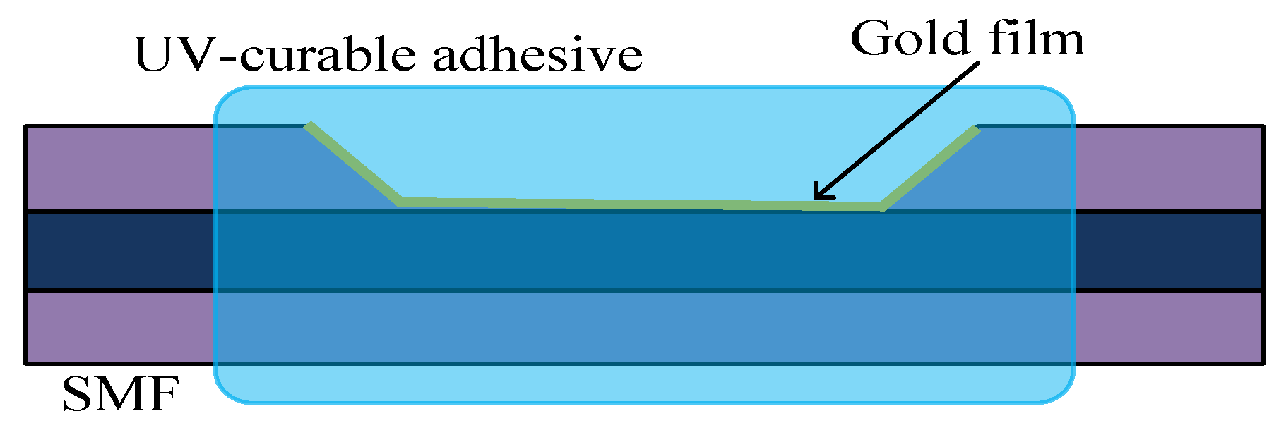
- Liu, S.; Cao, S.; Zhang, Z.; Wang, Y.; Liao, C.; Wang, Y. Temperature Sensor Based on Side-Polished Fiber SPR Device Coated with Polymer. Sensors 2019, 19, 4063. [Google Scholar] [CrossRef]
- Zeng, S.; Sreekanth, K.V.; Shang, J.-Z.; Yu, T.; Chen, C.-K.; Yin, F.; Baillargeat, D.; Coquet, P.; Ho, H.-P.; Kabashin, A.V.; et al. Graphene-Gold Metasurface Architectures for Ultrasensitive Plasmonic Biosensing. Adv. Mater. 2015, 27, 6163–6169. [Google Scholar] [CrossRef]
- Sreekanth, K.V.; Zeng, S.; Yong, K.; Yu, T. Sensitivity enhanced biosensor using graphene-based one-dimensional photonic crystal. Sens. Actuators B Chem. 2013, 182, 424–428. [Google Scholar] [CrossRef]
- Zeng, S.; Hu, S.; Xia, J.; Anderson, T.; Dinh, X.Q.; Meng, X.-M.; Coquet, P.; Yong, K. Graphene–MoS2 hybrid nanostructures enhanced surface plasmon resonance biosensors. Sens. Actuators B Chem. 2015, 207, 801–810. [Google Scholar] [CrossRef]
- Sharma, A.K.; Gupta, J. Enhancement in performance of an evanescent wave fiber optic sensor in the near-infrared region by graphene’s chemical potential. Photonics Nanostructures Fundam. Appl. 2018, 31, 147–153. [Google Scholar] [CrossRef]
- Zhang, C.; Li, Z.; Jiang, S.Z.; Li, C.; Xu, S.C.; Yu, J.; Li, Z.; Wang, M.H.; Liu, A.H.; Man, B.Y. U-bent fiber optic SPR sensor based on graphene/AgNPs. Sens. Actuators B Chem. 2017, 251, 127–133. [Google Scholar] [CrossRef]
- Nayak, J.K.; Parhi, P.; Jha, R. Graphene oxide encapsulated gold nanoparticle based stable fibre optic sucrose sensor. Sens. Actuators B Chem. 2015, 22, 835–841. [Google Scholar] [CrossRef]
- Kim, J.A.; Hwang, T.; Dugasani, S.R.; Amin, R.; Kulkarni, A.; Park, S.H.; Yeom, G.Y.; Reddy, D.S. Graphene based fiber optic surface plasmon resonance for bio-chemical sensor applications. Sens. Actuators B Chem. 2013, 187, 426–433. [Google Scholar] [CrossRef]
- Zhao, Y.; Tong, R.-J.; Chen, M.-Q.; Xia, F. Fluorescence Temperature Sensor Based on GQDs Solution Encapsulated in Hollow Core Fiber. IEEE Photon. Technol. Lett. 2017, 29, 1544–1547. [Google Scholar] [CrossRef]
- Qian, W.; Zhao, C.-L.; He, S.; Dong, X.; Zhang, S.; Zhang, Z.; Jin, S.; Guo, J.; Wei, H. High-sensitivity temperature sensor based on an alcohol-filled photonic crystal fiber loop mirror. Opt. Lett. 2011, 36, 1548–1550. [Google Scholar] [CrossRef]
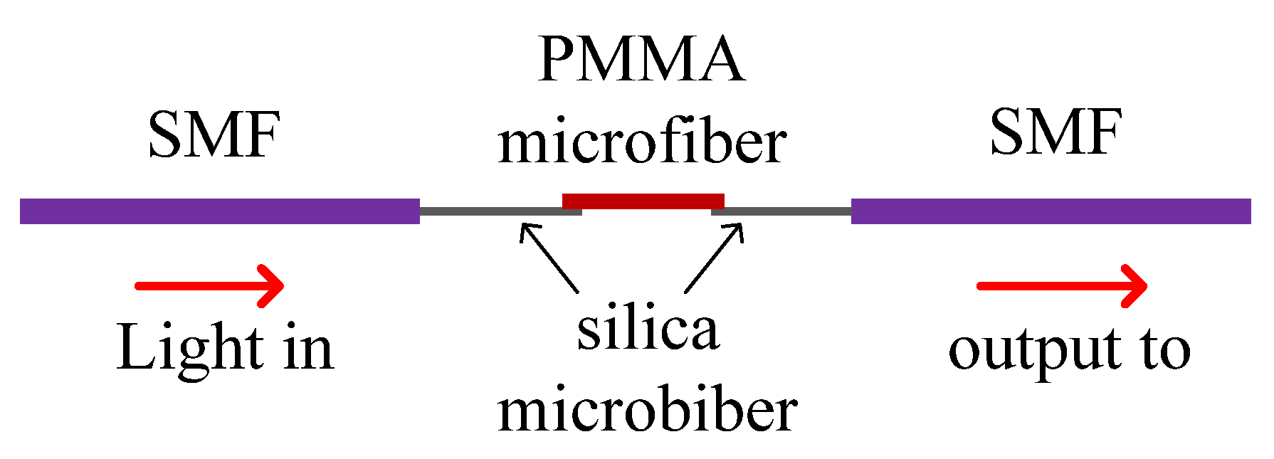
- Irawati, N.; Harun, S.W.; Rahman, H.A.; Chong, S.S.; Hamizi, N.A.; Ahmad, H. Temperature sensing using CdSe quantum dot doped poly(methyl methacrylate) microfiber. Appl. Opt. 2017, 56, 4675–4679. [Google Scholar] [CrossRef] [PubMed]
- Davies, E.; Viitala, R.; Salomäki, M.O.; Areva, S.; Zhang, L.; Bennion, I. Sol–gel derived coating applied to long-period gratings for enhanced refractive index sensing properties. J. Opt. Pure Appl. Opt. 2008, 11, 15501. [Google Scholar] [CrossRef]
- Hosoki, A.; Nishiyama, M.; Igawa, H.; Seki, A.; Choi, Y.; Watanabe, K. A surface plasmon resonance hydrogen sensor using Au/Ta2O5/Pd multi-layers on hetero-core optical fiber structures. Sens. Actuators B 2013, 185, 53–58. [Google Scholar] [CrossRef]
- Ruiz-Zamarreño, C.; Hernaez, M.; Del Villar, I.; Matias, I.R.; Arregui, F. Tunable humidity sensor based on ITO-coated optical fiber. Sens. Actuators B Chem. 2010, 146, 414–417. [Google Scholar] [CrossRef]
- Jiang, M.; Li, Q.-S.; Wang, J.-N.; Jin, Z.; Sui, Q.; Ma, Y.; Shi, J.; Zhang, F.; Jia, L.; Yao, W.-G.; et al. TiO2 nanoparticle thin film-coated optical fiber Fabry-Perot sensor. Opt. Express 2013, 21, 3083–3090. [Google Scholar] [CrossRef]
- Cheng, S.-F.; Chau, L.-K. Colloidal Gold-Modified Optical Fiber for Chemical and Biochemical Sensing. Anal. Chem. 2003, 75, 16–21. [Google Scholar] [CrossRef]
- Shao, Y.; Xu, S.; Zheng, X.; Wang, Y.; Xu, W. Optical Fiber LSPR Biosensor Prepared by Gold Nanoparticle Assembly on Polyelectrolyte Multilayer. Sensors 2010, 10, 3585–3596. [Google Scholar] [CrossRef]
- García, J.; Monzón-Hernández, D.; Manriquez, J.M.; Bustos, E. One step method to attach gold nanoparticles onto the surface of an optical fiber used for refractive index sensing. Opt. Mater. 2016, 51, 208–212. [Google Scholar] [CrossRef]
- Cennamo, N.; D’Agostino, G.; Donà, A.; Dacarro, G.; Pallavicini, P.; Pesavento, M.; Zeni, L. Localized Surface Plasmon Resonance with Five-Branched Gold Nanostars in a Plastic Optical Fiber for Bio-Chemical Sensor Implementation. Sensors 2013, 13, 14676–14686. [Google Scholar] [CrossRef]
- Tang, J.-L.; Cheng, S.-F.; Hsu, W.-T.; Chiang, T.-Y.; Chau, L.-K. Fiber-optic biochemical sensing with a colloidal gold-modified long period fiber grating. Sens. Actuators B Chem. 2006, 119, 105–109. [Google Scholar] [CrossRef]
- Ortega-Mendoza, J.G.; Vivanco, A.P.; Quitl, C.T.; Zaca-Morán, P.; Villegas-Hernández, D.; Chavez, F. Optical Fiber Sensor Based on Localized Surface Plasmon Resonance Using Silver Nanoparticles Photodeposited on the Optical Fiber End. Sensors 2014, 14, 18701–18710. [Google Scholar] [CrossRef] [PubMed]
- Raj, D.R.; Prasanth, S.; Vineeshkumar, T.; Sudarsanakumar, C. Ammonia sensing properties of tapered plastic optical fiber coated with silver nanoparticles/PVP/PVA hybrid. Opt. Commun. 2015, 340, 86–92. [Google Scholar] [CrossRef]
- Hu, J.; Jiang, M.; Lin, Z. Novel technology for depositing a Pd–Ag alloy film on a tapered optical fibre for hydrogen sensing. J. Opt. Pure Appl. Opt. 2005, 7, 593–598. [Google Scholar] [CrossRef]
- Li, Y.; Wang, Y.; Wen, C. Temperature and strain sensing properties of the zinc coated FBG. Optik 2016, 127, 6463–6469. [Google Scholar] [CrossRef]
- Shukla, S.; Sharma, N.K.; Sajal, V. Sensitivity enhancement of a surface plasmon resonance based fiber optic sensor using ZnO thin film: A theoretical study. Sensors Actuators B Chem. 2015, 206, 463–470. [Google Scholar] [CrossRef]
- Gupta, S.K.; Joshi, A.; Kaur, M. Development of gas sensors using ZnO nanostructures. J. Chem. Sci. 2010, 122, 57–62. [Google Scholar] [CrossRef]


| Materials | Thermal Expansion Coefficient (/°C) |
|---|---|
| PDMS | 300 × 10−6 |
| AL | 23.03 × 10⁻⁶ |
| Ti | 8.35 × 10⁻⁶ |
| Au | 14 × 10−6 |
| polyimide | 20 × 10−6–30 × 10−6 |
| SiO2 | 0.55 × 10⁻⁶ |
| MZI | SPR | F-P | FBG/ | PCF | |
|---|---|---|---|---|---|
| LPFG | |||||
| PDMS | 20 | 29 | 35 | 41 | |
| 75.04 pm/°C | 42 | −240.425 dB/RI | 32 | ||
| 21 | −1.551 nm/°C | 385.46 pm/°C | 0.042 nm/°C | ||
| 3101.8 pm/°C | 4613.73 nm/RIU | 36 (VOCs) | 33 | ||
| 22 | (Refractive Index Unit) | 1.17 pm/ppm | 255.4 pm/°C | ||
| applied pressure | 43 | (Parts Per Million) | 34 | ||
| 23 | 2323.4 nm/RIU | 37 | |||
| 0.1957 nm/°C | −2.850 nm/°C | 1.509 nm/°C | |||
| 24 | 44 | 38 (toluene) | |||
| −29.03 nm/N 2.17 nm/°C | −1.02 nm/°C | 1.4 nm/g.m3 | |||
| 25 | 1224 nm/RIU | 39 | |||
| applied | 0.13 dB/°C | ||||
| displacement | |||||
| 26 | |||||
| −41.58 pm/°C | |||||
| 27 | |||||
| 1.67 nm/°C | |||||
| 28 | |||||
| −0.4409 nm/°C | |||||
| 29 | |||||
| 580.6 pm/°C | |||||
| 30 | |||||
| −384 pm/°C | |||||
| polyimide | 86 | 84 | 76 | ||
| 0.0115 nm/°C | 85 | 12.7 pm/°C | |||
| 87 | 0.45 nm/(mol/L) | 1.2 pm/µε | |||
| 0.09648 nm/°C | (salinity) | 77 | |||
| 60.5 pm/‰ | 0.0094 nm/°C | ||||
| (salinity) | 0.0165 nm/M | ||||
| (salinity) | |||||
| 78 | |||||
| 79 | |||||
| 80 | |||||
| 1.97 mmol/L/h | |||||
| (cell growth) | |||||
| 81 | |||||
| 1.814 pm/με | |||||
| 82 | |||||
| 1.71 pm/%RH | |||||
| (humidity) | |||||
| 84 | |||||
| 0.742 nm/(mol/L) | |||||
| (salinity) | |||||
| UV-sensitive materials | 92 | 94 | 90 | 93 | |
| 24611.54 nm/RIU | 8800 nm/RIU | 0.19 nm/°C | 0.057 nm/°C | ||
| −13.27 nm/°C | −0.978 nm/°C | 260 dB/RIU | |||
| 91 | |||||
| 249 pm/°C | |||||
| 1130 pm/MPa | |||||
| graphene | 96 | 49 | 49, (glucose) | ||
| 8.25 × 10²/RIU | 51 | 51, (gas sensors) | |||
| 97 | 102 | 0.344 nm%−1 | |||
| 99 | 123.7 pm/°C | ||||
| 100 | |||||
| 2.449 ∆A/RIU | |||||
| (sucrose) | |||||
| 101 | |||||
| alcohol | 103, | ||||
| 6.6 nm/°C | |||||
| methyl methacrylate | 104 | ||||
| 58.5 pm/°C | |||||
| Sol-gel derived Ti, SiO2 | 105 | ||||
| 1067.15 nm/RIU | |||||
| Au-Ta2O5-Pd/Au | 50 | 50 (glucose) | |||
| 106 (hydrogen sensor) | 113 | ||||
| 109 | −17.93 nm/RIU 37.31 dB/RIU | ||||
| 110 | |||||
| 111 | |||||
| 765 nm/RIU | |||||
| 112 | |||||
| TiO2 | 107 | 45 | 108, | 45, | |
| 5.4 RH/nm | (DNA aptamer) | 69.38 dB/RIU | (DNA aptamer) | ||
| (humidity) | |||||
| Ag/PVP/PVA | 51 | 51 | |||
| 52 | 52 | ||||
| 114 | |||||
| 67.6 nm/RIU | |||||
| 115 | |||||
| 0.9 counts/ppm | |||||
| (ammonia) | |||||
| Zn/ZnO | 117 | ||||
| 49.59 pm/°C |
© 2020 by the authors. Licensee MDPI, Basel, Switzerland. This article is an open access article distributed under the terms and conditions of the Creative Commons Attribution (CC BY) license (http://creativecommons.org/licenses/by/4.0/).
Share and Cite
Li, C.; Yang, W.; Wang, M.; Yu, X.; Fan, J.; Xiong, Y.; Yang, Y.; Li, L. A Review of Coating Materials Used to Improve the Performance of Optical Fiber Sensors. Sensors 2020, 20, 4215. https://doi.org/10.3390/s20154215
Li C, Yang W, Wang M, Yu X, Fan J, Xiong Y, Yang Y, Li L. A Review of Coating Materials Used to Improve the Performance of Optical Fiber Sensors. Sensors. 2020; 20(15):4215. https://doi.org/10.3390/s20154215
Chicago/Turabian StyleLi, Changxu, Wenlong Yang, Min Wang, Xiaoyang Yu, Jianying Fan, Yanling Xiong, Yuqiang Yang, and Linjun Li. 2020. "A Review of Coating Materials Used to Improve the Performance of Optical Fiber Sensors" Sensors 20, no. 15: 4215. https://doi.org/10.3390/s20154215
APA StyleLi, C., Yang, W., Wang, M., Yu, X., Fan, J., Xiong, Y., Yang, Y., & Li, L. (2020). A Review of Coating Materials Used to Improve the Performance of Optical Fiber Sensors. Sensors, 20(15), 4215. https://doi.org/10.3390/s20154215