A Spectrum-Aware Priority-Based Link Scheduling Algorithm for Cognitive Radio Body Area Networks


Abstract
:1. Introduction
- The usage of cognitive radio has been applied to WBANs in the healthcare applications. The emergency data channel is used only for emergency data of CRBANs while the normal data will be transmitted by using the normal data channel.
- The CRBANs with high traffic priority could play the role of a primary user in the unlicensed channel, which aims to access the spectrum earlier than other CRBANs. As a consequence, the latency of the data with high traffic priority is guaranteed to be less than a threshold value.
- The neighboring CRBANs can share or reuse the spectrum to increase the network throughput because the idle spectrum is limited.
2. Related Works
3. System Models
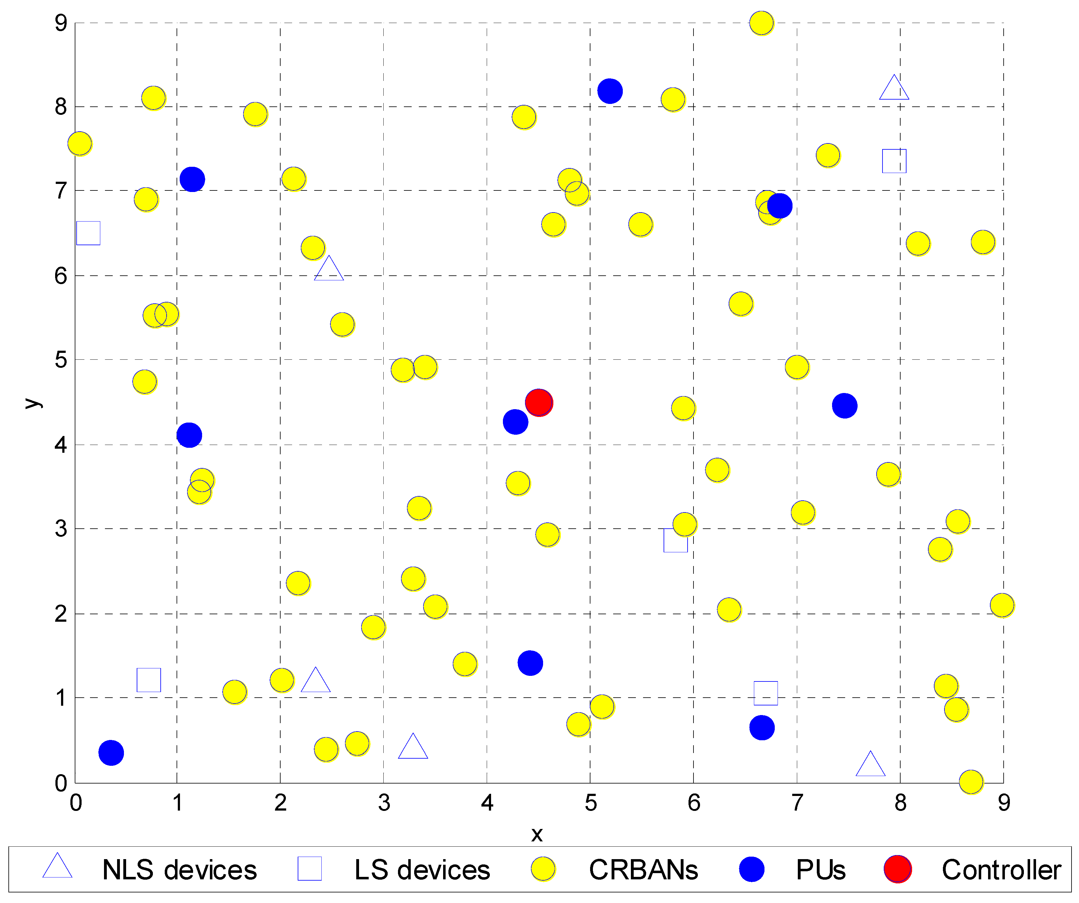
3.1. Network Model
3.2. Channel Sensing
4. Spectrum-Aware Priority-Based Link Scheduling
4.1. MAC Superframe Structure
4.2. Problem Formulation
4.3. Inter-CRBAN Transmission
4.4. Link Scheduling Algorithm for CRBANs
| Algorithm 1 Link scheduling algorithm at the coordinator on DataCh. |
| Input:N CRBANs, at each CRBAN {List of idle channels CIi(t), list of neighbors NBIi(t, Ck), maximum transmit power PTxdata} |
| Output: A set of valid data channels {Cx} for N CRBANs |
| 1. While all WBANs are not scheduled |
| 2. At coordinator of CBi: received the NBIi(t) (list of neighbors) |
| 3. For each CBy∈NBIi(t) |
| 4. Check the list of idle channels CIy(t) of each CBy |
| 5. CINBI(t) = CINBI(t) ∪CIy(t) |
| 6. End for |
| 7. If (CINBI(t) == CIi(t)) |
| 8. Find CBx with the highest priority value in Prio(CBx) = max(Prio(NBIi(t)) |
| 9. If (Prio(CBi) > (Prio(CBx)) |
| 10. Broadcast Grouping_Mesg = {CBx, CBi} to NBIi(t) |
| 11. CBi, CBx takes the first channel in Cz ∈ CIi(t), |
| 12. Set TNB2 as (24) |
| 13. Set Bi(ti, Cz) = 1; Bx(tx,Cz) = 1; |
| 14. Broadcast the Update_Used_Channel = {Bi(t, Cz), Bx(tx, Cz)} |
| 15. Else |
| 16. Waiting for the Grouping_Mesg |
| 17. If (CBi∈Grouping_Mesg) |
| 18. Update Bi(ti, Cz) = 1 |
| 19. Else |
| 20. CBi takes the random channel Cz ∈ CIi(t) |
| 21. End if |
| 22. End if |
| 23. Else |
| 24. CBi will select a channel Cz = {Ck|Ck ∈ CIi(t), max(ΔTt(Ck))} as in (17b) |
| 25. Broadcast the Update_Used_Channel = {Bi(t, Cz)} |
| 26. End if |
| 27. Update_Used_Channel = set of valid data channels {Cx} for N CRBANs |
| 28. End while |
4.5. Intra-CRBAN Transmission
| Algorithm 2 Intra-CRBAN transmission at the coordinator. |
| Input: set of {M} sensor nodes, historical packet delivery ratio PDR{t − 1,M} |
| Output: A TDMA scheduled for M sensor nodes |
| 1. Estimate the number of packet delivery ratio at each sensor PDR(t − 1) = {PDRj|j ∈ M} |
| 2. Sort PDR in descending order |
| 3. For each sensor nodes |
| 4. Schedule the j-th sensor with the lowest PDR(j) at the first available timeslot |
| 5. Remove j of {M} |
| 6. End for |
| 7. Broadcast beacon signal in CtrlCh, Beacon = {schedule({M}), index of DataCh Ck, length of superframe Ti, start time of next superframe} |
| Algorithm 3 Intra-CRBAN transmission at the sensor nodes. |
| Input: set of {M} sensor nodes, historical packet delivery ratio PDR{t − 1,M} |
| Output: A TDMA scheduled for M sensor nodes |
| 1. Wait for beacon signal on CtrlCh |
| 2. Change the working channel to DataCh according to beacon signal |
| 3. Transmit data in the assigned timeslot |
| 4. Go back to sleep after receiving ACK from the coordinator |
5. Performance Evaluation
5.1. Simulation Environment
5.2. Simulation Results and Discussion
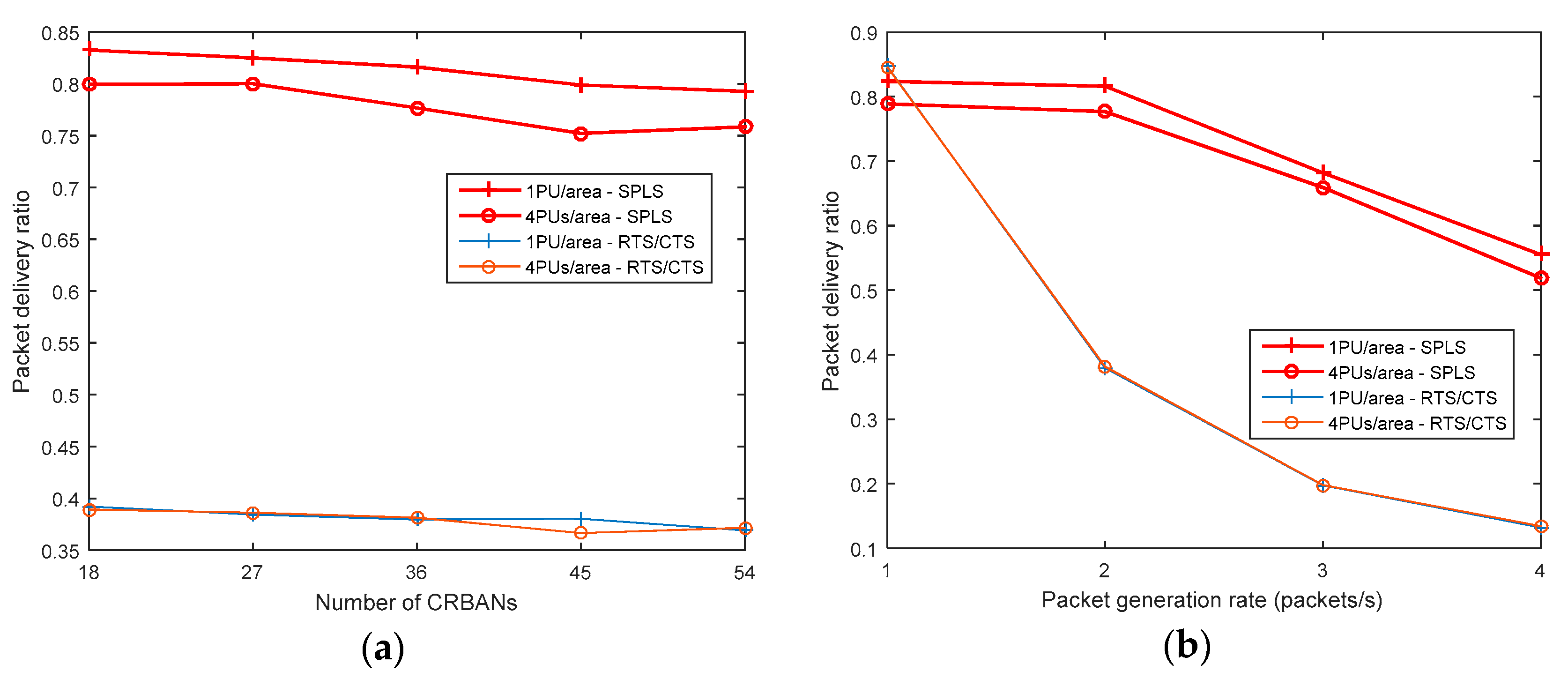
5.2.1. Packet Delivery Ratio
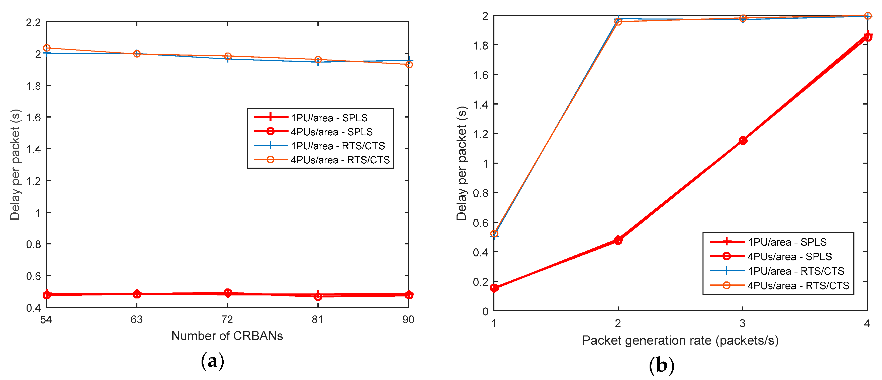
5.2.2. Packet Delay
5.2.3. Network Throughput
5.2.4. Energy Consumption
6. Conclusions
Author Contributions
Funding
Acknowledgments
Conflicts of Interest
References
- Ullah, S.; Khan, P.; Ullah, N.; Higgins, H.; Saleem, S.; Kwak, K.S. A Review of WBANs for Medical Applications. Int. J. Commun. Netw. Syst. Sci. 2009, 2, 797–803. [Google Scholar]
- Movassaghi, S.; Abolhasan, M.; Lipman, J.; Smith, D.; Jamalipour, A. Wireless Body Area Networks: A Survey. IEEE Commun. Surv. Tutor. 2014, 16, 1658–1686. [Google Scholar] [CrossRef]
- IEEE. IEEE Standard for Local and Metropolitan Area Networks—Part 15.6: Wireless Body Area Networks; IEEE Std 802.15.6-2012; IEEE: New York, NY, USA, 2012; pp. 1–271. [Google Scholar]
- Naeem, M.; Pareek, U.; Lee, D.C.; Khwaja, A.S.; Anpalagan, A. Wireless Resource Allocation in Next Generation Healthcare Facilities. IEEE Sens. J. 2015, 15, 1463–1474. [Google Scholar] [CrossRef]
- Phunchongharn, P.; Hossain, E.; Niyato, D.; Camorlinga, S. A Cognitive Radio System for E-health Applications in a Hospital Environment. IEEE Wirel. Commun. 2010, 17, 20–28. [Google Scholar] [CrossRef]
- Chavez-Santiago, R.; Nolan, K.; Holland, O.; De Nardis, L.; Ferro, J.; Barroca, N.; Borges, L.; Velez, F.; Goncalves, V.; Balasingham, I. Cognitive Radio for Medical Body Area Networks using Ultra Wideband. IEEE Wirel. Commun. 2012, 19, 74–81. [Google Scholar] [CrossRef]
- Rathee, D.; Rangi, S.; Chakarvarti, S.K.; Singh, V.R. Recent Trends in Wireless Body Area Network (WBAN) Research and Cognition Based Adaptive WBAN Architecture for Healthcare. Health Technol. 2014, 4, 239–244. [Google Scholar] [CrossRef]
- Le, T.T.; Moh, S. An Interference-Aware Traffic-Priority-Based Link Scheduling Algorithm for Interference Mitigation in Multiple Wireless Body Area Network. Sensors 2016, 16, 2190. [Google Scholar] [CrossRef]
- Biglieri, E.; Goldsmith, A.; Greenstein, L.; Mandayam, N.; Poor, H. Capacity of cognitive radio networks. In Principle of Cognitive Radio; Cambridge University Press: Cambridge, UK, 2012; pp. 41–101. [Google Scholar]
- Chávez-Santiago, R.; Jankunas, D.; Fomin, V.V.; Balasingham, I. Dual-band Cognitive Radio for Wearable Sensors in Hospitals. In Proceedings of the 8th International Symposium on Medical Information and Communication Technology (ISMICT), Firenze, Italy, 2–4 April 2014; pp. 1–5. [Google Scholar]
- Chávez-Santiago, R.; Balasingham, I. Cognitive Radio for Medical Wireless Body Area Networks. In Proceedings of the IEEE 16th International Workshop on Computer Aided Modeling and Design of Communication Links and Networks (CAMAD), Kyoto, Japan, 10–11 June 2011; pp. 148–152. [Google Scholar]
- Ahmed, T.; Moullec, Y. A QoS Optimization Approach in Cognitive Body Area Networks for Healthcare Applications. Sensors 2017, 17, 780. [Google Scholar] [CrossRef] [PubMed]
- León, O.; Hernández-Serrano, J.; Garrigues, C.; Rifà-Pous, H. A Cognitive-radio-based Method for Improving Availability in Body Sensor Networks. Int. J. Distrib. Sens. Netw. 2015, 11, 272869. [Google Scholar] [CrossRef]
- Chepuri, S.P.; de Francisco, R.; Leus, G. Performance Evaluation of an IEEE 802.15.4 Cognitive Radio Link in the 2360-2400 MHz Band. In Proceedings of the IEEE Wireless Communications and Networking Conference, Cancun, Quintana Roo, Mexico, 28–31 March 2011; pp. 2155–2160. [Google Scholar]
- Nhan, N.Q.; Gautier, M.; Berder, O. Asynchronous MAC protocol for spectrum agility in Wireless Body Area Sensor Networks. In Proceedings of the International Conference on Cognitive Radio Oriented Wireless Networks and Communications (CROWNCOM), Oulu, Finland, 9–12 June 2014; pp. 1–6. [Google Scholar]
- Bhandari, S.; Moh, S. A Survey of MAC Protocols for Cognitive Radio Body Area Networks. Sensors 2015, 15, 9189–9209. [Google Scholar] [CrossRef] [PubMed]
- Le, T.T.T.; Pan, S.; Moh, S. Link Scheduling for Cognitive Radio Body Area Networks. In Proceedings of the 6th International Conference on Smart Media and Applications (SMA 2017), Boracay, Philippines, 17–19 December 2017; pp. 57–59. [Google Scholar]
- Cotton, S.L.; D’Errico, R.; Oestges, C. A Review of Radio Channel Models for Body Centric Communications. Radio Sci. 2014, 49, 371–388. [Google Scholar] [CrossRef] [PubMed]
- Hu, Z.H.; Nechayev, Y.; Hall, P. Measurements and statistical analysis of the transmission channel between two wireless body area networks at 2.45 GHz and 5.8 GHz. In Proceedings of the 2010 Conference Proceedings ICECom, 20th International Conference on Applied Electromagnetics and Communications, Dubrovnik, Croatia, 20–23 September 2010; pp. 1–4. [Google Scholar]
- Zurita Ares, B.; Park, P.G.; Fischione, C.; Speranzon, A.; Johansson, K.H. On Power Control for Wireless Sensor Networks: System Model, Middleware Component and Experimental Evaluation. In Proceedings of the 2007 European Control Conference (ECC), Kos, Greece, 2–5 July 20017; pp. 4293–4300. [Google Scholar]
- Saleem, Y.; Rehmani, M.H. Primary Radio User Activity Models for Cognitive Radio Networks: A Survey. J. Netw. Comput. Appl. 2014, 43, 1–16. [Google Scholar] [CrossRef]
- Shen, Q.; Liu, J.; Yu, H.; Ma, Z.; Li, M.; Shen, Z.; Chen, C. Adaptive Cognitive Enhanced Platform for WBAN. In Proceedings of the IEEE/CIC International Conference on Communications in China (ICCC), Xi’an, China, 12–14 August 2013; pp. 739–744. [Google Scholar]
- Salim, S.; Moh, S. An Energy-efficient Game-theory-based Spectrum Decision Scheme for Cognitive Radio Sensor Networks. Sensors 2016, 16, 1009. [Google Scholar] [CrossRef] [PubMed]
- Abo-Zahhad, M.; Farrag, M.; Ali, A.; Amin, O. An energy consumption model for wireless sensor networks. In Proceedings of the 5th International Conference on Energy Aware Computing Systems & Applications, Cairo, Egypt, 24–26 March 2015; pp. 1–4. [Google Scholar]


| Priority | WBAN Services |
|---|---|
| 0 (lowest) | Non-medical services |
| 1 | Mixed medical and non-medical services |
| 2 | General health services |
| 3 (highest) | Highest priority medical services |
| Notations | Explanation |
|---|---|
| N | Number of CRBANs |
| CBi | i-th CRBAN, 1 ≤ i ≤ N |
| M | Number of sensors per CRBAN |
| sij | j-th sensor of i-th CRBAN, 1 ≤ j ≤ M |
| ts | Timeslot |
| CtrlCh | Common control channel |
| EDataCh | Emergency data channel |
| DataCh | Normal data channel |
| qthres | Threshold value of probability that a busy channel becomes idle |
| pthres | Threshold value of probability that an idle channel becomes busy |
| d(i,j) | Distance between the coordinators of two CRBANs |
| R | Transmission range of a CRBAN |
| Uk | k-th unlicensed channel Uk ∈ CU, 1 ≤ k ≤ U, where U is the number of unlicensed channels, and CU is the set of unlicensed channels |
| Lk | k-th licensed channel Lk ∈ CL, 1 ≤ k ≤ L, where L is the number of licensed channels, and CL is the set of licensed channels |
| K | Number of channels occupied by PUs |
| A | Number of remaining channels to schedule N CRBANs |
| γi(Ck) | Observed SINR at i-th CRBAN in a channel Ck, Ck ∈ CL ∪ CU |
| γth | SINR threshold |
| CIi(t) | List of idle channels observed at i-th CRBAN |
| Bi(t,Ck) | Bi(t, Ck) = 1 means that i-th CRBAN occupies channel Ck in superframe t; Ck ∈ CIi(t). |
| NIi(t, Ck) | List of neighbors that sense the same Ck as i-th CRBAN |
| NBIi(t) | List of neighbors of i-th CRBAN |
| Statei(Ck, t) = {Idle, Busy} | Status of channel Ck of CBi at time t |
| SFi | Length of superframe of i-th CRBAN |
| SFmax | Maximum length of superframe in the schedule |
| IFi(t, Ck) | Interference level of i-th CRBAN at channel Ck |
| Tmax | Maximum number of superframe in the schedule |
| Parameter | Value |
|---|---|
| Bit rate | 250 Kbps |
| Synchronization time with CRC | 10 ms |
| Data slot time | 10 ms |
| Exchange message length | 2 bytes |
| Number of CRBANs | 54–90 (default: 72) or 5~10 per area (default: 7) |
| Number of sensor per CRBAN | 10 |
| Number of PUs | 9–36 (1–4 PUs per area) |
| Packet generation rate | 1–4 packets/s at each sensor (default = 2 packets/s) |
| Number of unlicensed channels | 10 |
| Superframe length | 100 ms |
| Frequency | 2400–2483.5 MHz |
| Bandwidth | 1 MHz |
| Data packet size | 50 bytes (normal data) |
| Transmitted power of CRBAN | 10 dBm |
| Transmission range of controller | 10 m |
| Transmission range of CRBAN | 2 m |
| Transmit current [15] | 17.4 mA |
| Receive current [15] | 19.7 mA |
| Energy consumption per channel switching [15] | 2 mJ |
| Voltage | 3.3 V |
| Receiver sensitivity at controller | −80 dBm |
© 2019 by the authors. Licensee MDPI, Basel, Switzerland. This article is an open access article distributed under the terms and conditions of the Creative Commons Attribution (CC BY) license (http://creativecommons.org/licenses/by/4.0/).
Share and Cite
Le, T.T.T.; Moh, S. A Spectrum-Aware Priority-Based Link Scheduling Algorithm for Cognitive Radio Body Area Networks. Sensors 2019, 19, 1640. https://doi.org/10.3390/s19071640
Le TTT, Moh S. A Spectrum-Aware Priority-Based Link Scheduling Algorithm for Cognitive Radio Body Area Networks. Sensors. 2019; 19(7):1640. https://doi.org/10.3390/s19071640
Chicago/Turabian StyleLe, Thien Thi Thanh, and Sangman Moh. 2019. "A Spectrum-Aware Priority-Based Link Scheduling Algorithm for Cognitive Radio Body Area Networks" Sensors 19, no. 7: 1640. https://doi.org/10.3390/s19071640
APA StyleLe, T. T. T., & Moh, S. (2019). A Spectrum-Aware Priority-Based Link Scheduling Algorithm for Cognitive Radio Body Area Networks. Sensors, 19(7), 1640. https://doi.org/10.3390/s19071640