Cold-Rolled Strip Steel Stress Detection Technology Based on a Magnetoresistance Sensor and the Magnetoelastic Effect

Abstract
:1. Introduction
2. Stress Detection Principle and Theoretical Analysis
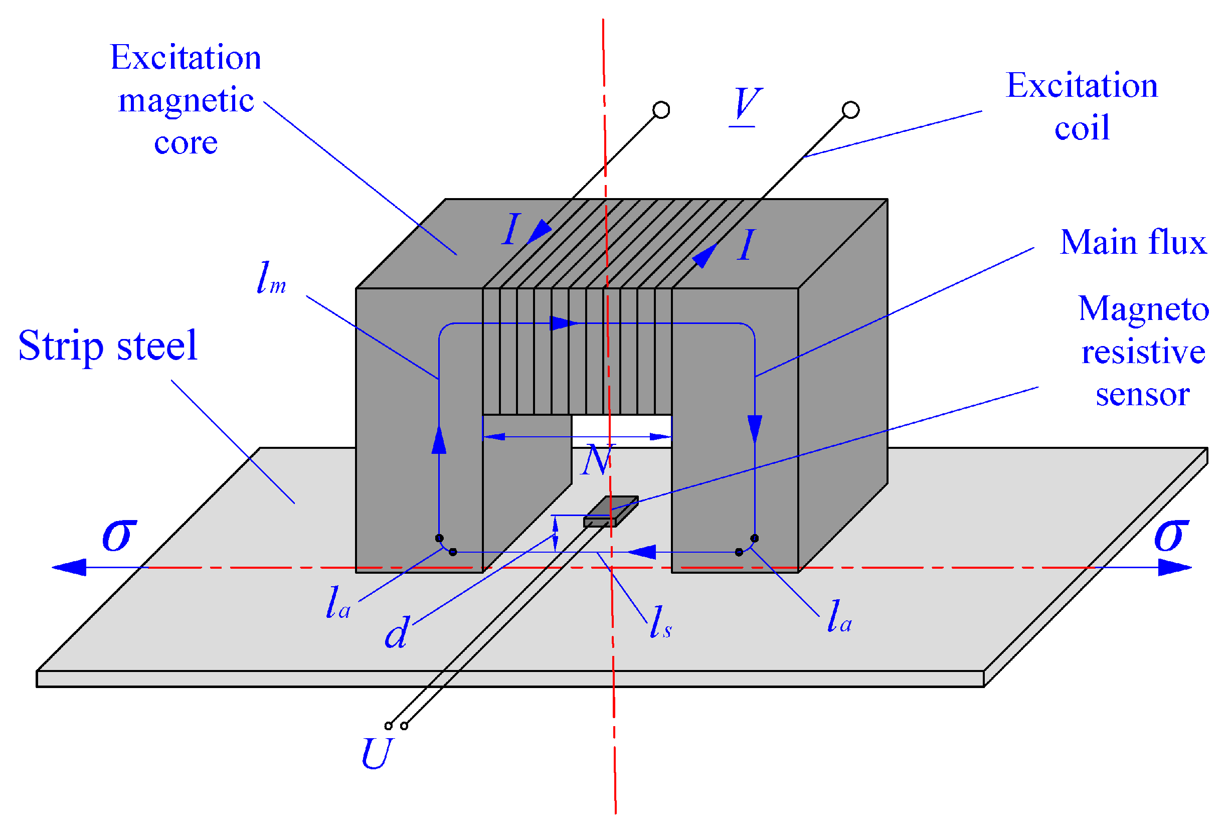
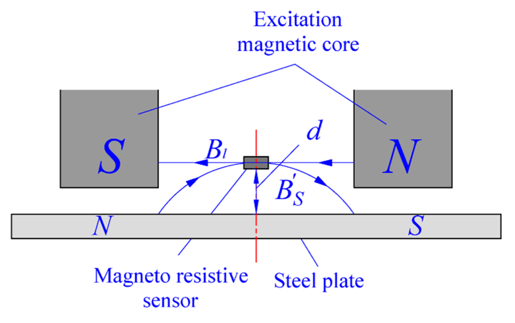
2.1. Basic Detection Principle
2.2. Relationships in Signal Conversion
2.2.1. Δσ→Δμ
2.2.2. Δμ→ΔBs
2.2.3. ΔBs→ΔBr
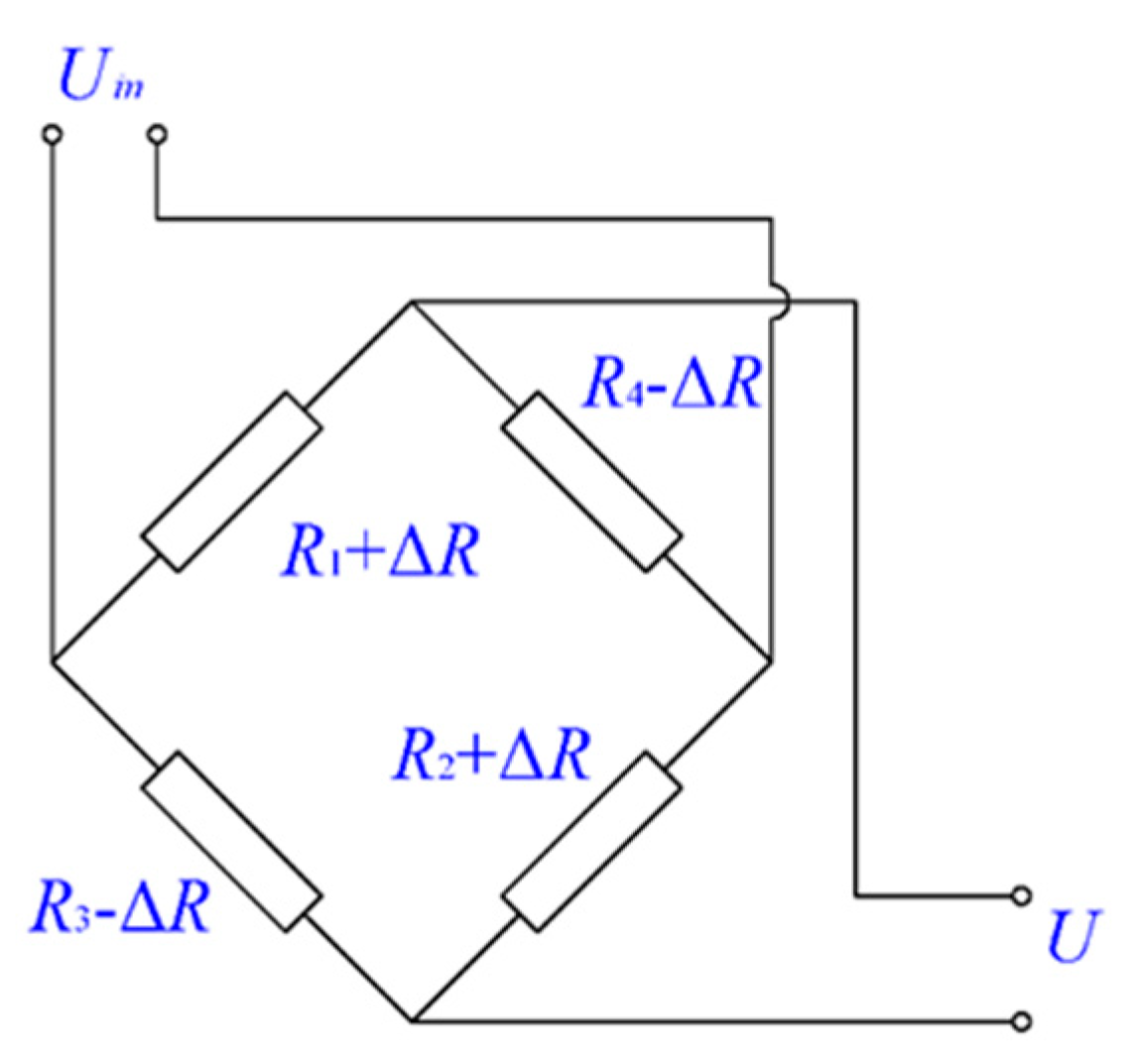
2.2.4. ΔBr→ΔR→ΔU
2.3. Analysis of Stress Detection Sensitivity
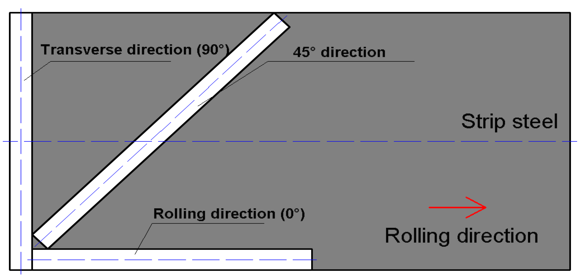
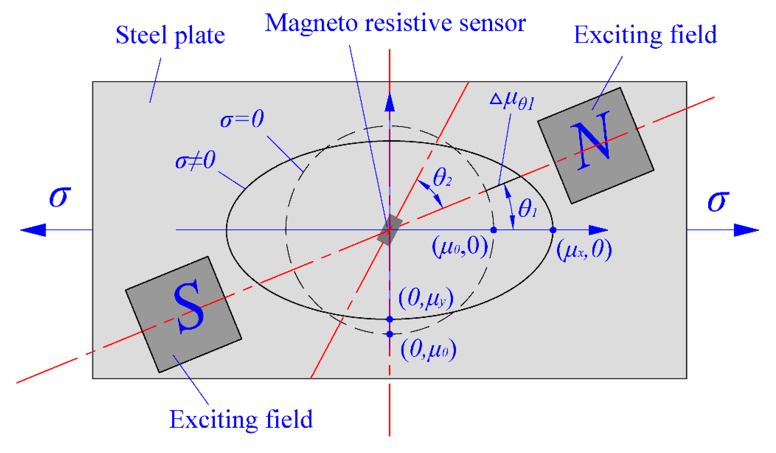
2.4. Relationship of Relative Orientations between Stress Directions, Main Flux Direction and Sensor Detection Directions
3. Establishment of Stress Detection System
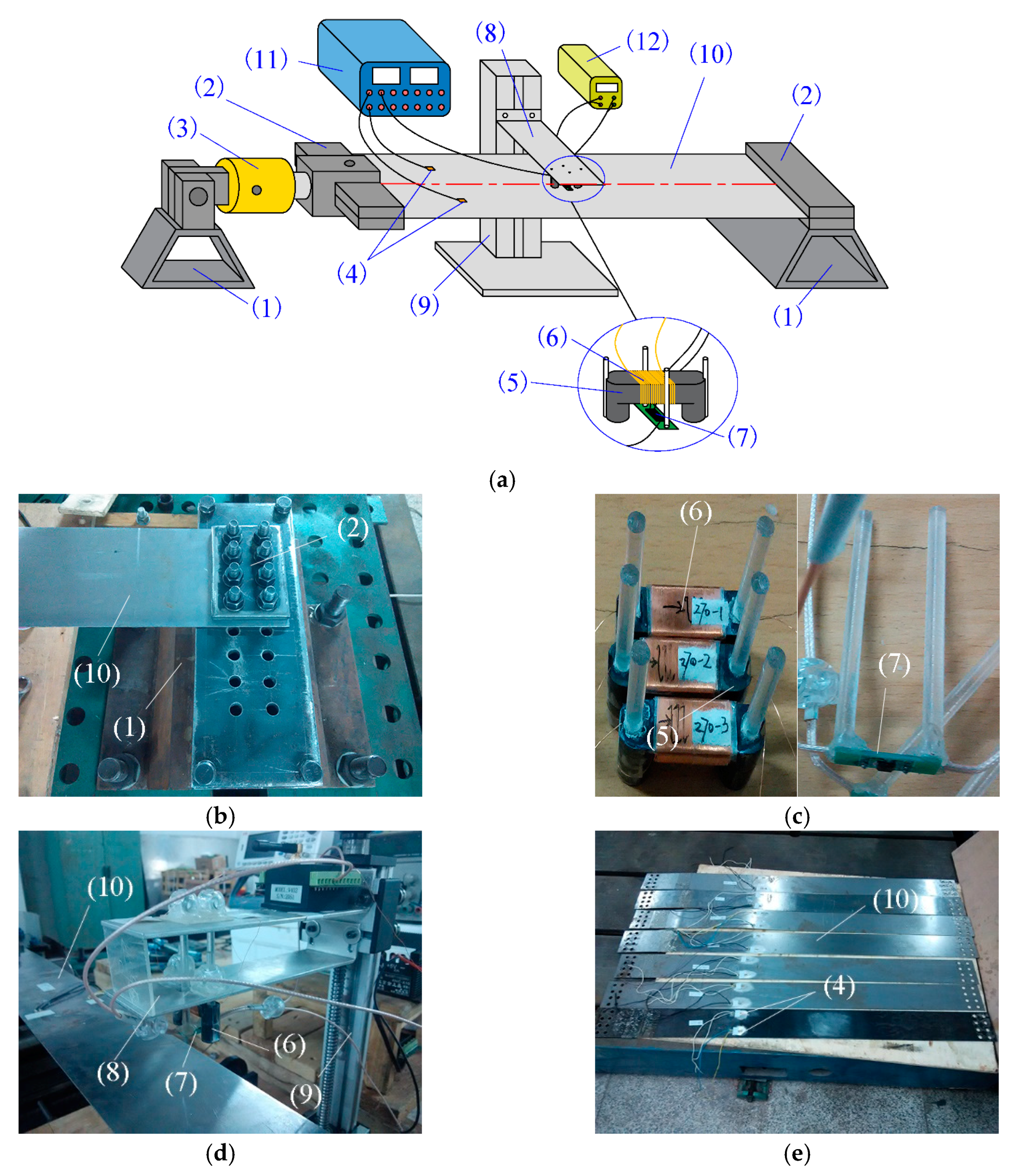
3.1. Experimental Set-Up
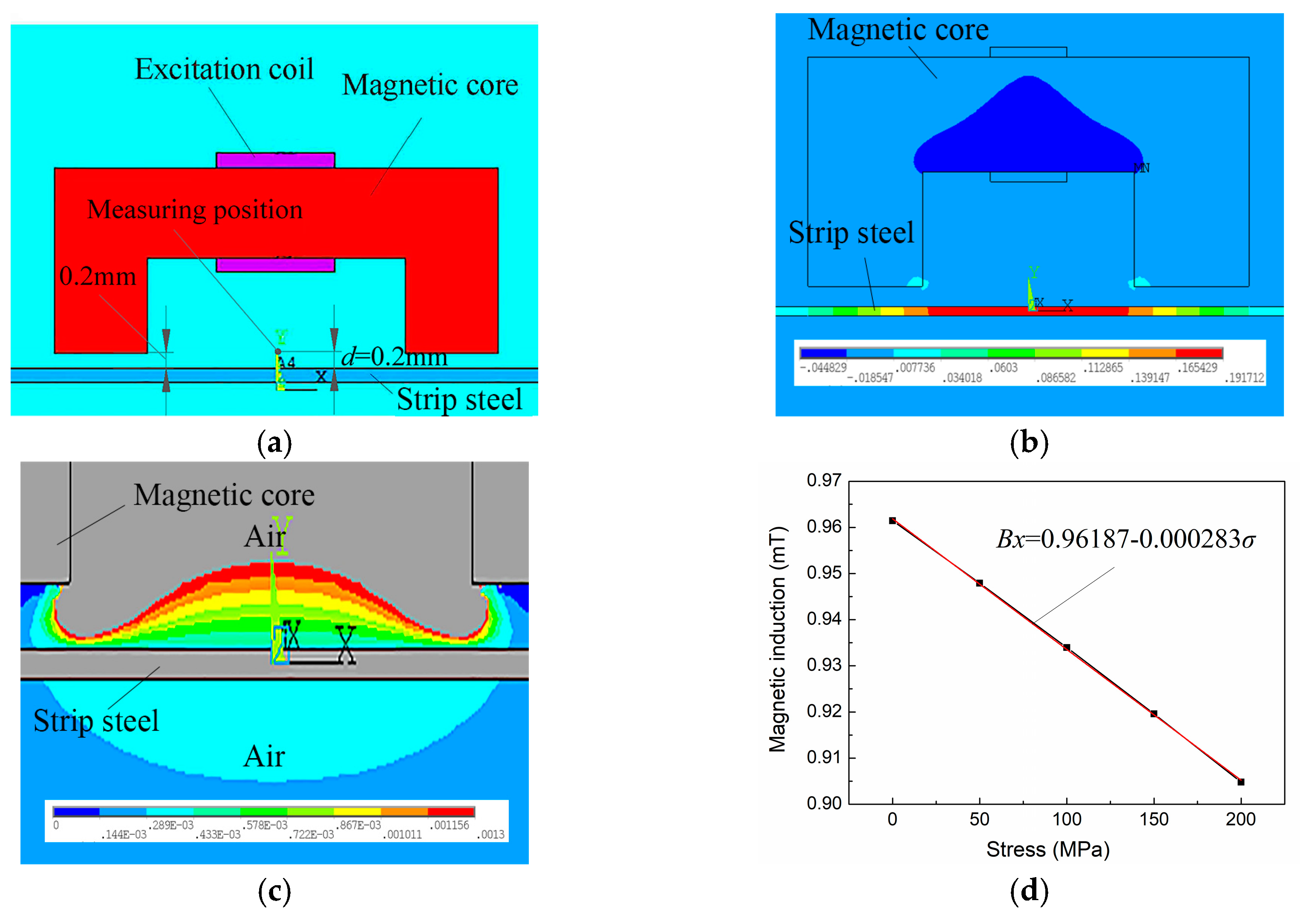
3.2. Design of Exciting Parameter and Model Selection of Magneto-Resistive Sensor
4. Analysis of Stress Detection Experiment and Influence Factor
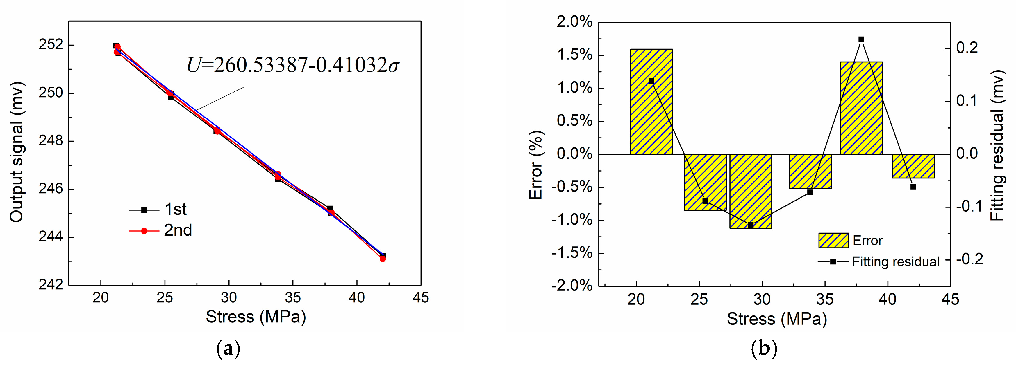
4.1. Stress Detection Error and Repeatability
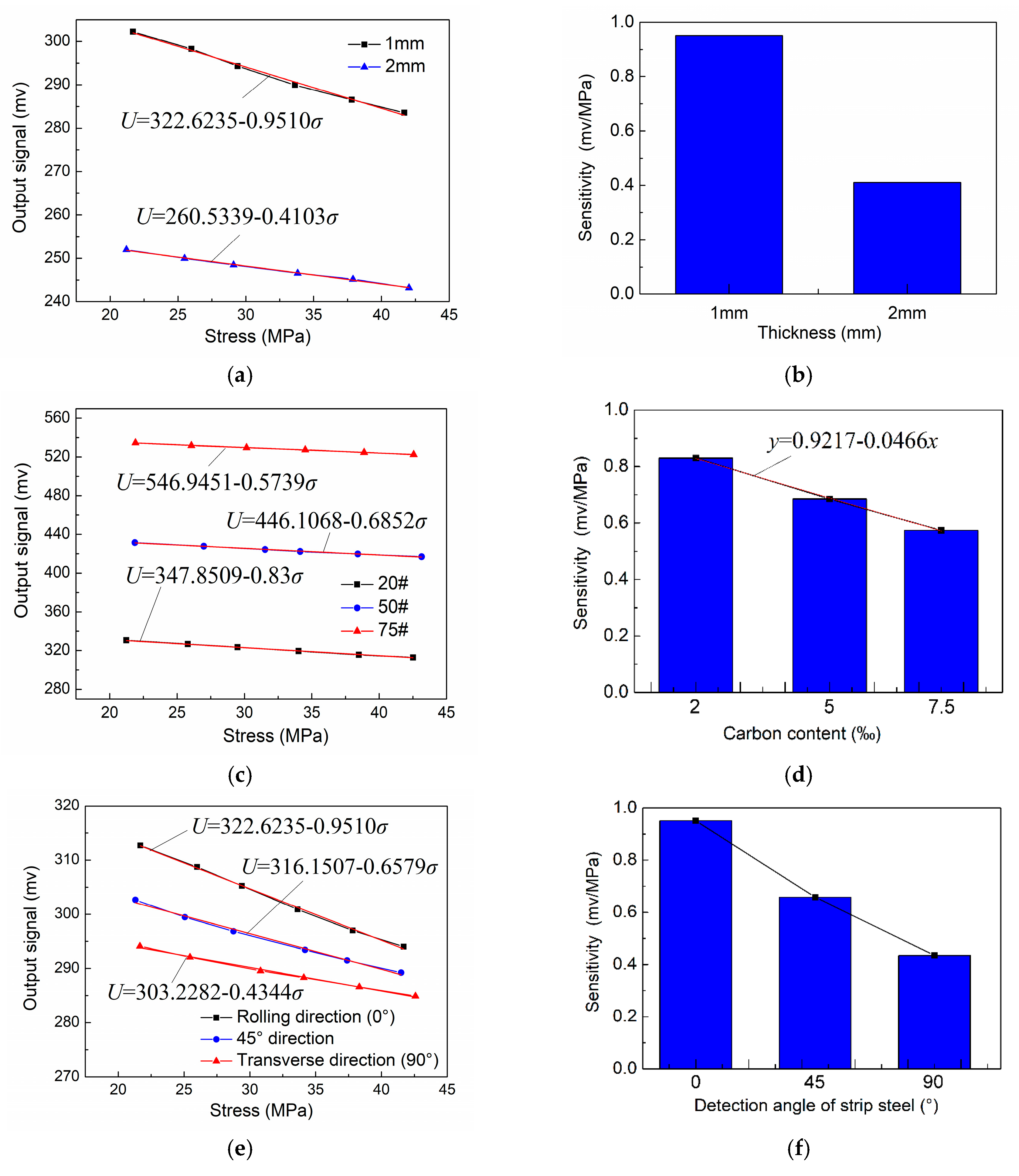
4.2. Influencing Factors of Stress Detection Signals
5. Conclusions
Author Contributions
Funding
Conflicts of Interest
References
- Wang, G.D. Technology innovation and development direction of iron and steel industry. Iron Steel 2015, 50, 1–10. [Google Scholar] [CrossRef]
- Yan, P.; Shan, N. Review on assessment methods for shape control performance of strip rolling mills. J. Mech. Eng. 2017, 53, 26–44. [Google Scholar]
- Wang, D.C.; Liu, H.M.; Liu, J. Research and development trend of shape control for cold rolling strip. Chin. J. Mech. Eng. 2017, 30, 1–14. [Google Scholar] [CrossRef]
- Liu, H.M.; Lian, J.C.; Peng, Y. Third-power spline function strip element method and its simulation of the three-dimensional stresses and deformations of cold strip rolling. J. Mater. Process. Technol. 2001, 116, 235–243. [Google Scholar] [CrossRef]
- The Method of Flatness Measurement and Control. Available online: http://en.cnki.com.cn/Article_en/CJFDTOTAL-ZXJX200204000.htm (accessed on 19 May 2018).
- Wang, P.; Zhang, D.; Liu, J.; Wang, J.; Yu, X. Research and application of the flatness measurement calculation model on cold rolling mill. J. Mech. Eng. 2011, 4, 014. [Google Scholar] [CrossRef]
- Yu, B.Q.; Yang, L.P.; Liu, H.M. Research on the entire roll type shape meter of cold rolling strip and its industrial application. Adv. Mater. Res. 2012, 572, 359–363. [Google Scholar] [CrossRef]
- Wu, H.; Liu, H.; Wang, K. Thermal reliability research on entire roller-embedded shapemeter roll. Int. J. Adv. Manuf. Technol. 2018, 94, 3189–3198. [Google Scholar] [CrossRef]
- Yamada, H.; Uchiyama, S.; Takeuchi, K.; Wakiwaka, H.; Kishimoto, S.; Ito, M. Noncontact measurement of bending stress using a magnetic anisotropy sensor. IEEE Trans. Magn. 1987, 23, 2422–2424. [Google Scholar] [CrossRef]
- Wakiwaka, H.; Uchiyama, S.; Masada, E.; Yamada, H. Effect of magnetic field on magnetic anisotropy sensor. IEEE Transl. J. Magn. Jpn. 2008, 7, 234–240. [Google Scholar] [CrossRef]
- Wakiwaka, H.; Kobayashi, M.; Yamada, H. Stress measurement using a magnetic anisotropy sensor utilizing ac demagnetization. J. Magn. Soc. Jpn. 1991, 14, 396–401. [Google Scholar] [CrossRef]
- Liu, H.; Dun, C.; Dou, L.; Yang, W. Theoretical analysis of magnetic sensor output voltage. J. Magn. Magn. Mater. 2011, 323, 1667–1670. [Google Scholar] [CrossRef]
- Kypris, O.; Nlebedim, I.C.; Jiles, D.C. Measuring stress variation with depth using barkhausen signals. J. Magn. Magn. Mater. 2016, 407, 377–395. [Google Scholar] [CrossRef]
- Jackiewicz, D. Stress Assessment in Steel Truss Structures on the Basis of Magnetoelastic Effects; Springer International Publishing: Midtown Manhattan, NY, USA, 2016. [Google Scholar]
- Vourna, P.; Ktena, A.; Tsakiridis, P.E.; Hristoforou, E. An accurate evaluation of the residual stress of welded electrical steels with magnetic barkhausen noise. Measurement 2015, 71, 31–45. [Google Scholar] [CrossRef]
- Zhang, Q.; Su, Y.; Zhang, L.; Jia, B.; Luo, J. Magnetoelastic effect-based transmissive stress detection for steel strips: Theory and experiment. Sensors 2016, 16, 1382. [Google Scholar] [CrossRef] [PubMed]
- Yu, S.; Zang, Y. A theoretical investigation of non-contact magnetoelastic sensor and experimentations. In Proceedings of the Conference of Automation in Continuous Casting Production in China, Beijing, China, 19–20 August 2006. [Google Scholar]
- Kashiwaya, K. Fundamentals of nondestructive measurement of biaxial stress in steel utilizing magnetoelastic effect under low magnetic field. Jpn. J. Appl. Phys. 1991, 30, 2932–2942. [Google Scholar] [CrossRef]
- Baibich, M.N.; Broto, J.M.; Fert, A.; Dau, F.N.V.; Petroff, F.; Etienne, P.; Creuzet, G.; Friederich, A.; Chazelas, J. Giant magnetoresistance of (001)fe/(001)cr magnetic superlattices. Phys. Rev. Lett. 1988, 61, 2472. [Google Scholar] [CrossRef] [PubMed]
- Ye, C.; Udpa, L.; Udpa, S. Optimization and validation of rotating current excitation with gmr array sensors for riveted structures inspection. Sensors 2016, 16, 1512. [Google Scholar] [CrossRef] [PubMed]
- Tehranchi, M.M.; Ranjbaran, M.; Eftekhari, H. Double core giant magneto-impedance sensors for the inspection of magnetic flux leakage from metal surface cracks. Sens. Actuators A Phys. 2011, 170, 55–61. [Google Scholar] [CrossRef]
- Sharatchandra Singh, W.; Rao, B.P.C.; Vaidyanathan, S.; Jayakumar, T.; Raj, B. Detection of leakage magnetic flux from near-side and far-side defects in carbon steel plates using a giant magneto-resistive sensor. Meas. Sci. Technol. 2007, 19, 015702. [Google Scholar] [CrossRef]
- Jogschies, L.; Klaas, D.; Kruppe, R.; Rittinger, J.; Taptimthong, P.; Wienecke, A.; Rissing, L.; Wurz, M.C. Recent developments of magnetoresistive sensors for industrial applications. Sensors 2015, 15, 28665–28689. [Google Scholar] [CrossRef] [PubMed]
- Barbieri, F.; Trauchessec, V.; Caruso, L.; Trejo-Rosillo, J.; Telenczuk, B.; Paul, E.; Bal, T.; Destexhe, A.; Fermon, C.; Pannetier-Lecoeur, M. Local recording of biological magnetic fields using giant magneto resistance-based micro-probes. Sci. Rep. 2016, 6. [Google Scholar] [CrossRef] [PubMed]
- Wang, S.L.; Wang, W.; San-Qing, S.U.; Zhang, S.F. A Magneto-Mechanical Model on Differential Permeability and Stress of Ferromagnetic Material. J. Xian Univ. Sci. Technol. 2005, 25, 288–291. [Google Scholar]
- Liang, M.; Xue, K. Calculation of the magnetic field of the finite solenoid with a rectangular cross section. Phys. Eng. 2018, 28, 57–61. [Google Scholar]
- Gao, W.P.; Dong, W.; Hong-Bo, F.U.; Zhao, M.L. Analysis of external electromagnetic field intensity of finite length solenoid using MATLAB. Phys. Exam. Test. 2014, 32, 51–54. [Google Scholar]
- Chunsheng, L.I.; Yang, Z.; Huang, T. Magnetic field analysis of limited solenoid with electric current. Mod. Electron. Tech. 2009, 32, 28–30. [Google Scholar]
- Xiaomeng, L.I.; Ding, H.; Guo, G.; Bai, S. Simulation of stress-magnetization effect for q235 steel. J. Test Meas. Technol. 2013, 27, 167–173. [Google Scholar]
- Yonglin, M.A.; Zhao, N.; Liu, B.; Zhang, H.; Zhao, J.; Zhang, L.; Xing, S. Evolution of structure and texture of common grain-oriented silicon steel during cold rolling and annealing. Mater. Mech. Eng. 2017, 41, 25–29. [Google Scholar]
- Sanjari, M.; He, Y.; Hilinski, E.J.; Yue, S.; Kestens, L.A.I. Texture evolution during skew cold rolling and annealing of a non-oriented electrical steel containing 0.9 wt % silicon. J. Mater. Sci. 2017, 52, 3281–3300. [Google Scholar] [CrossRef]
- Eskandari, M.; Mohtadi-Bonab, M.A.; Szpunar, J.A. Evolution of the microstructure and texture of x70 pipeline steel during cold-rolling and annealing treatments. Mater. Des. 2016, 90, 618–627. [Google Scholar] [CrossRef]


| Signal Conversion Process | Conversion Coefficient | Influencing Parameter |
|---|---|---|
| Δσ→Δμ |
| |
| Δμ→ΔBs |
| |
| ΔBs→ΔBr |
| |
| ΔBr→ΔR |
| |
| ΔR→ΔU |
|
| Parameter | Value | Parameter | Value |
|---|---|---|---|
| Young modulus | 210 | Electrical conductivity | |
| Poisson ratio | 0.3 | Electrical resistivity | |
| Density | 7850 | Saturation induction | 2.5 |
| Tensile strength | 370 | saturation magnetostriction | |
| Yield strength | 235 | Initial permeability | 500 |
| Parameter | Value | Parameter | Value |
|---|---|---|---|
| Linear region (mT) | ±3.0 | Operating temperature (°C) | −40–125 |
| Sensitivity (mV/V/mT) | 49.0 | Maximum applied magnetic field (Oe) | 1500 |
| Input voltage range (V) | 1–7 | Resolution (mOe) | 0.1 |
| Operating frequency (Hz) | DC, 1 M | Nonlinearity (%) | 2.0 |
| Exciting Magnetic Core | U22 Manganese Zinc Ferrite | Model of Sensor | TMR2102 |
|---|---|---|---|
| Exciting current (mA) | 49.0 | Vertical distance between detection point and strip steel (mm) | 2 |
| Number of turns of excitation coil | DC, 1 M | Materials of excitation coil | Enameled copper wire with 0.02 mm diameter |
© 2018 by the authors. Licensee MDPI, Basel, Switzerland. This article is an open access article distributed under the terms and conditions of the Creative Commons Attribution (CC BY) license (http://creativecommons.org/licenses/by/4.0/).
Share and Cite
Guan, B.; Zang, Y.; Han, X.; Zheng, K. Cold-Rolled Strip Steel Stress Detection Technology Based on a Magnetoresistance Sensor and the Magnetoelastic Effect. Sensors 2018, 18, 1638. https://doi.org/10.3390/s18051638
Guan B, Zang Y, Han X, Zheng K. Cold-Rolled Strip Steel Stress Detection Technology Based on a Magnetoresistance Sensor and the Magnetoelastic Effect. Sensors. 2018; 18(5):1638. https://doi.org/10.3390/s18051638
Chicago/Turabian StyleGuan, Ben, Yong Zang, Xiaohui Han, and Kailun Zheng. 2018. "Cold-Rolled Strip Steel Stress Detection Technology Based on a Magnetoresistance Sensor and the Magnetoelastic Effect" Sensors 18, no. 5: 1638. https://doi.org/10.3390/s18051638
APA StyleGuan, B., Zang, Y., Han, X., & Zheng, K. (2018). Cold-Rolled Strip Steel Stress Detection Technology Based on a Magnetoresistance Sensor and the Magnetoelastic Effect. Sensors, 18(5), 1638. https://doi.org/10.3390/s18051638