1. Introduction
Wireless sensor networks have become increasingly common in recent years, as they support an ever-expanding array of applications, in agriculture [
1], marine environment monitoring [
2], ambient assisted living [
3], industry [
4], healthcare [
5], and beyond. Often, such networks do not have a dedicated licensed frequency band, but operate in the existing radio environment. They may make use of open bands (e.g., ISM—Industrial, Scientific, Medical), which do not require licenses [
6]. Due to limitations on transmit power, open bands are especially suitable when the operating range of each node is not very large. In complex application scenarios which include large distances or multiple users, cellular wireless systems can be used for data transfer from the sensor network to the core network. This technology can be combined with low power, short distance systems such as ZigBee or Bluetooth, which operate in the ISM band [
7]. Multiple transmission standards are still available in the ISM band.
In the near future, the fifth generation of wireless communication systems (5G) will also become more widely used. This set of wireless technologies combines low-power, low-data rate transmission with high-data rate, low latency links. Numerous wireless sensor networks that utilize low power nodes transmit low amounts of data at low transmission speeds. These will benefit from the development of the special low power transmission protocols that 5G will make available in the 700 MHz band [
8]. At the same time, 5G systems will enable high data rates in the 3.5 GHz band, making this band attractive for designers of nodes which aggregate measurement data from wireless sensor networks [
9].
The wideband and multiband antennas have received a lot of research attention in the last few years. Numerous multiband and multi-system transmission schemes which require such antennas have been put forward. In [
10], a novel wide-band microstrip antenna for wideband applications is proposed which consists of a square radiating patch and a partial ground plane. Since the antenna bandwidth covers the range of 2.1711 to 4.0531 GHz it can be used for Wireless Local Area Network (WLAN), WiMAX (Worldwide Interoperability for Microwave Access—a family of wireless communication standards) and Long Term Evolution (LTE) systems. The antenna presented in [
11] is based on a microstrip design as well. It is a modified rectangular patch antenna with the U-shaped defected ground structure (DGS) unit and two parasitic elements (open-loop-ring resonators). It can operate in 4 frequency bands from 4.4 GHz up to 10 GHz and is suitable for applications in WLAN and WiMAX systems. The design of multiband antenna whose geometry is controlled by many parameters can be significantly improved with computer optimization technique. In [
12] the multiband antenna is presented with the radiator which uses the inverted “F” geometry. The successful utilization of the two-stage optimization algorithm resulted with the design that covers two bands: 824–960 MHz and 1710–2170 MHz. In this paper, we describe the design and procedure of optimization for a four-band antenna to be used in wireless sensor networks. The novel antenna we present is able to operate effectively in two open bands, 2.4 GHz and 5.8 GHz, as well as in two bands that are licensed and allocated for 5G wireless systems, 0.7 GHz and 3.5 GHz. The bands listed in
Table 1 are likely to be used in wireless sensor networks. There are already many small low power wireless transmission modules designed for ISM bands (bands 2 and 4 in
Table 1). The bands allocated for 5G systems (bands 1 and 3 in
Table 1) will use low power protocols developed for the Internet of Things. It will also be possible to achieve backhaul transmission in the 3.5 GHz band with 5G systems.
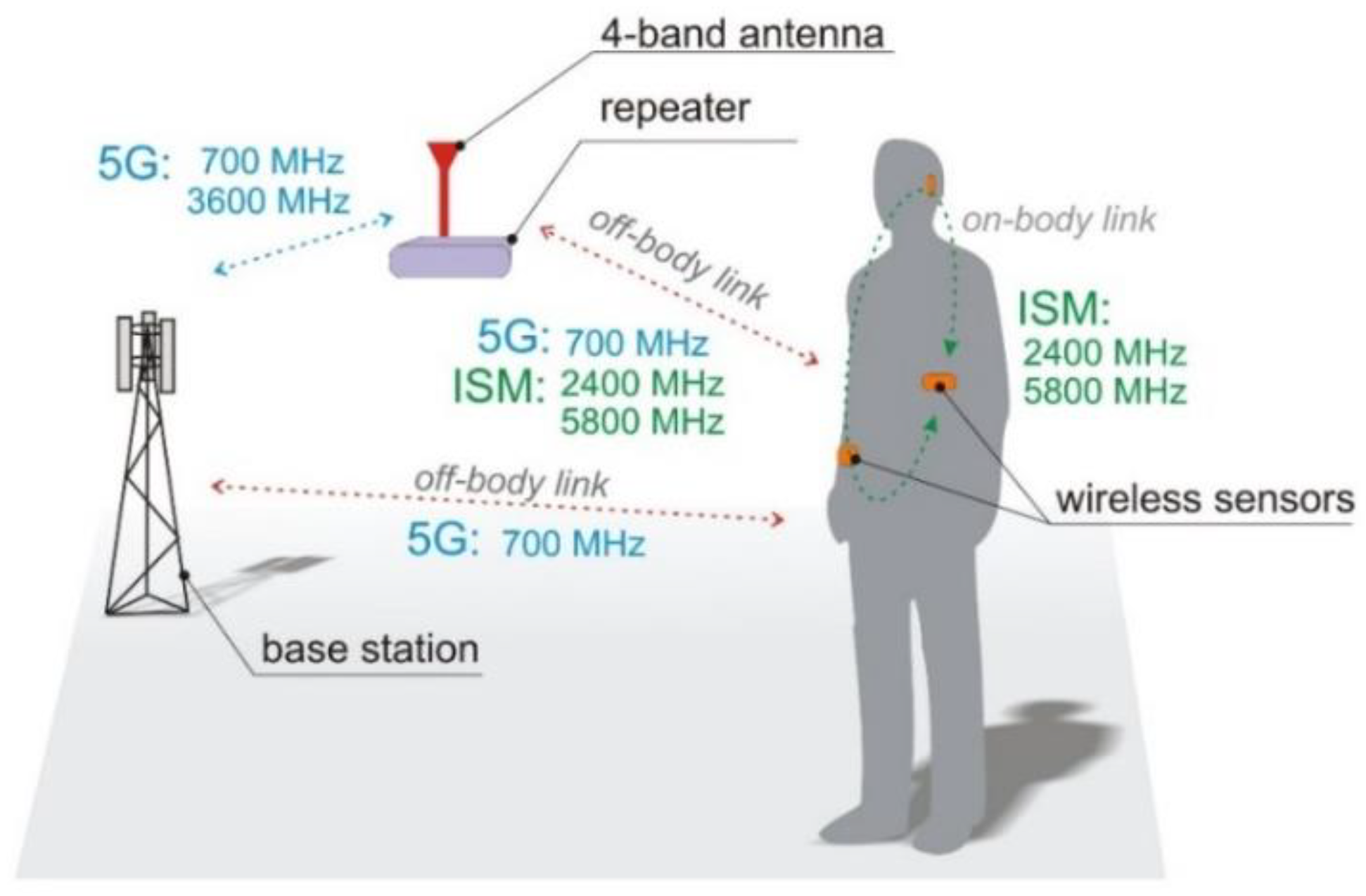
The potential data transmission scenario in which the four-band antenna will be used is presented in
Figure 1. It is assumed that the antenna can be connected to a four-band transceiver which will communicate with a wireless body area network in bands 1, 2 and 4 of
Table 1. ISM bands (2 and 4) are widely used for wireless body area networks due to the availability of low power transceivers. Nodes in wireless body area networks will soon also operate in band 1, and be compatible with the 5G Internet of Things. Band 3 can be utilized for high-speed transmission in 5G systems. These assumptions justify the selection of the bands covered by the proposed antenna.
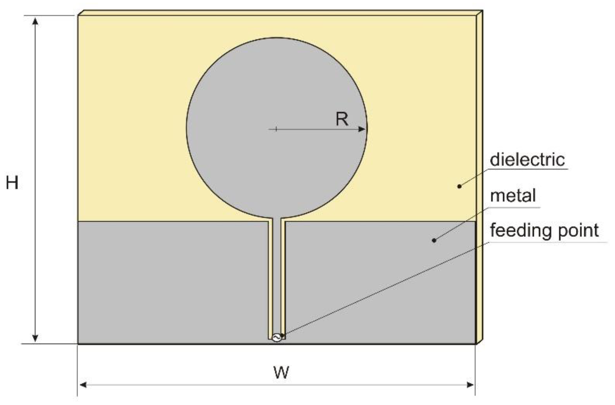
The initial antenna considered for this application was a coplanar waveguide (CPW) fed circular disc monopole antenna, illustrated in
Figure 2. A detailed description of this antenna can be found in [
13]. The antenna was designed for ultra wideband (UWB) systems, covering the frequency range from 2.27 GHz to 12 GHz. The original dimensions were: radius R = 25 mm and width W = 90 mm. The antenna was designed on 1.6 mm thick dielectric substrate with relative permittivity equal to 3.
To obtain UWB antenna operation in the lower frequency range of 703 MHz (band 1), it was necessary to redesign the original antenna. For this purpose, a numerical model of a circular disc monopole antenna was created in Remcom XFdtd software [
14]. This program uses the Finite Difference Time Domain method (FDTD) to simulate electromagnetic devices [
15]. The lower frequency of operation was achieved by increasing the radius of the circular part to R = 45 mm. The width of the antenna was in this case equal to W = 200 mm and height was increased to H = 165 mm for the same dielectric substrate. The impedance matching of this antenna is presented in
Figure 3. The desired bandwidth was achieved with the Voltage Standing Wave Ratio VSWR < 2.5, which is not a satisfactory result. Further increasing the antenna radius resulted in improved matching for the lower frequency of interest, but performance for the upper band deteriorated. Moreover, the dimensions of the antenna (200 mm × 165 mm) and its surface area equal to 0.033 m
2 made this design rather impractical for applications in wireless sensor networks, if they should have small nodes.
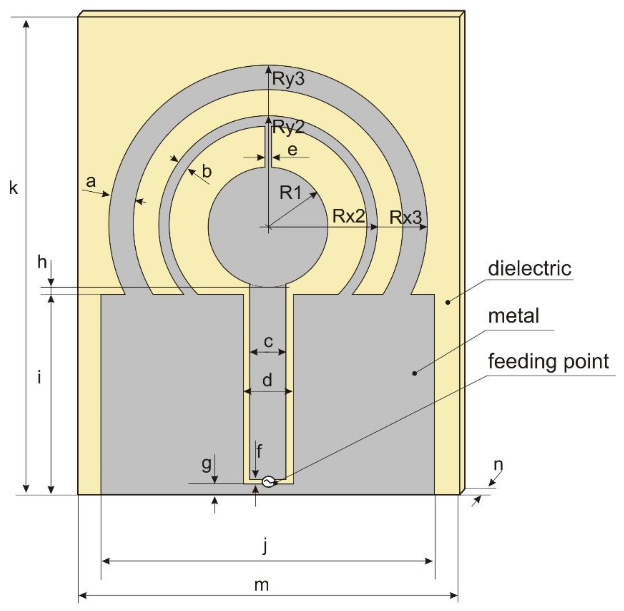
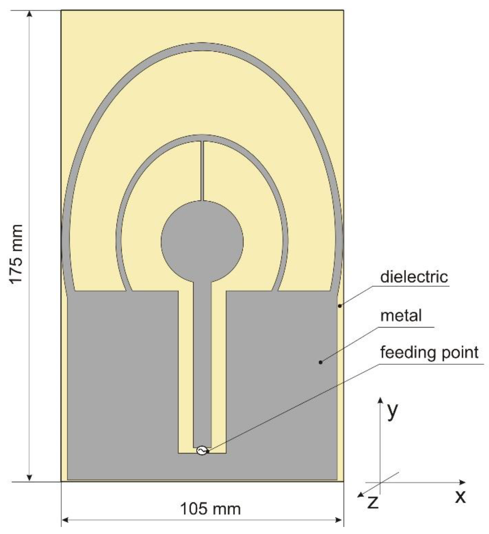
To overcome the limitations of the circular disc monopole antenna, a new design was proposed and developed for a four-band antenna. The antenna geometry is presented in
Figure 4. It is fed by a coplanar waveguide and consists of one full internal circle and two external rings (circular or elliptical). The design parameters are listed in
Table 2. Initial values were obtained by trial and error using Remcom XFdtd software ver. 7.6.0.2. The original design covers the two middle bands with a satisfactory level of impedance matching (VSWR < 2.3), but the impedance matching in the bands 1 and 4 was insufficient and the VSWR in band 1 was less than 4.5. The impedance matching of the initial design is presented in
Figure 5. The performance of this antenna depends strongly on the geometrical configuration. Of the 18 design parameters listed in
Table 2, the first 9 have a strong influence on impedance matching.
The large number of parameters made further improvement of the proposed antenna using trial and error very difficult, because of the tremendous computational effort required to simulate many possible combinations of parameter values. We therefore employed an automated optimization algorithm. The application of optimization algorithms can significantly improve antenna performance [
16,
17,
18,
19,
20]. Nine design parameters were included in the optimization process, while the other nine remained fixed. The goal was to improve impedance matching in the four bands without degrading the radiation properties of the antenna. The impedance properties of the antenna were evaluated against the VSWR parameter calculated for the reference impedance of 50 Ω. The radiation properties of the antenna were assessed in terms of radiation efficiency (RE), i.e., the ratio of radiated power to the input power at the feed point.
2. Multi-Objective Optimization Algorithm
The optimization of multiband antennas with respect to impedance matching and radiation efficiency raises a bi-objective optimization problem. Moreover, the multiple evaluation of both objective functions based on full-wave electromagnetic simulations makes the optimization procedure computationally costly. To help with these difficulties, several years ago one of the authors developed a simple yet effective algorithm based on a multi-objective (1+1) (i.e., one parent is used to create one offspring) evolution strategy (P-EStra), which is presented in [
21,
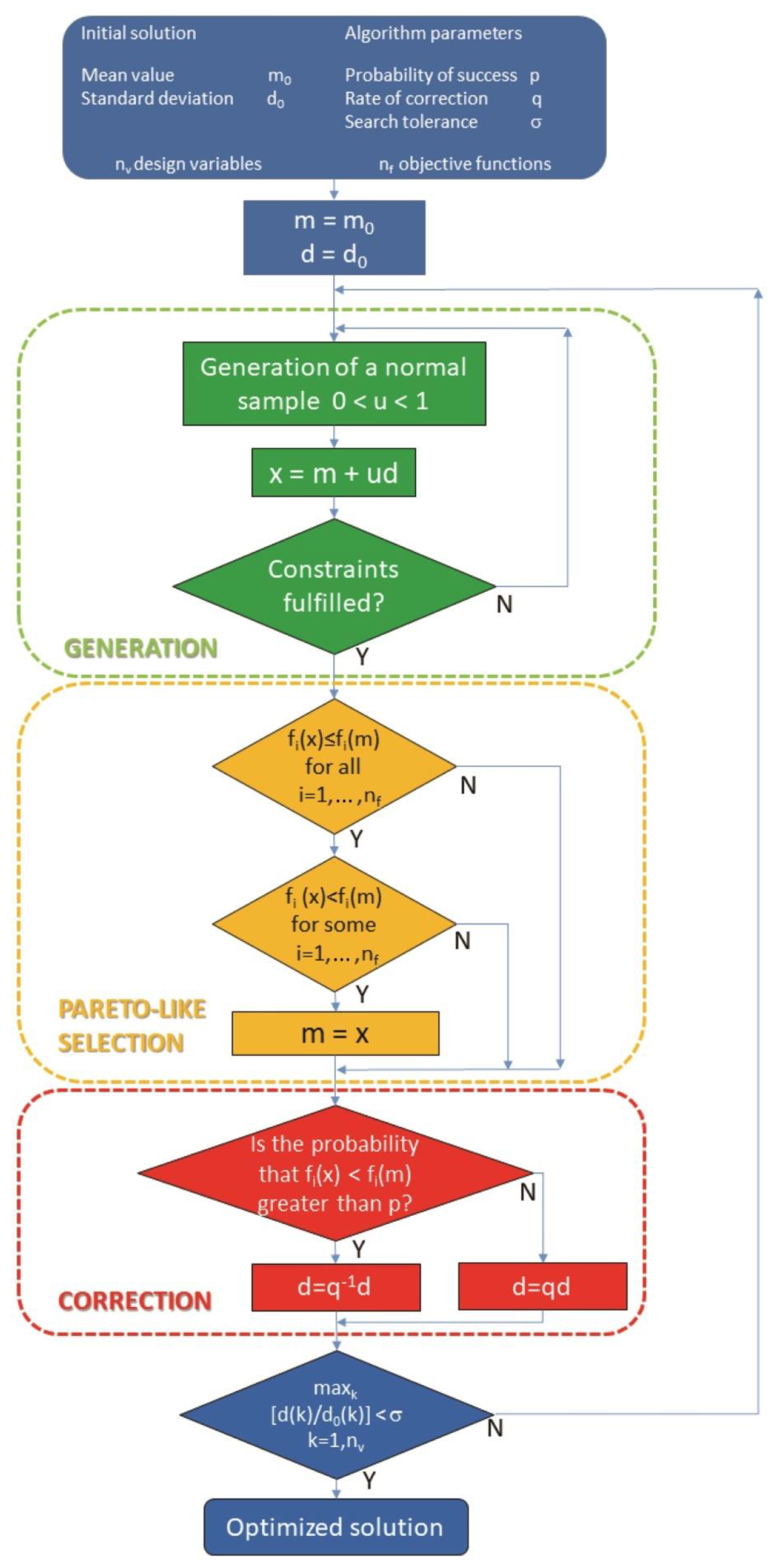
22]. The flow-chart of the algorithm is shown in
Figure 6. It is implemented in such a way that a new design vector
x (offspring solution) is generated from the current design vector
m (parent solution) according to (1)
where
d is the standard deviation associated with
m, while
is a normally distributed perturbation. Provided it fulfills the problem constraints, solution
x is accepted if
x dominates the current design vector
m (parent solution), i.e., given
nf objective functions
according to the Pareto optimality criterion [
22]. Otherwise, vector
m is retained.
Vector
d, which drives the search, is in turn updated in the following way: given the correction rate
, in the
k-th iteration, either
or
is set to force a larger (2a) or smaller (2b) standard deviation of the Gaussian distribution associated with
x in the next iteration. The choice of
dk+1 value depends on the probability of successful iteration, i.e., the rate of success in improving the objectives. The solution vector
x and the standard-deviation vector
d are both subject to mutation. In a basic (1+1) implementation, the operator of Pareto-like selection allows the best individual, whether parent or offspring, to survive to the next generation. In this way, given an initial solution there is a non-zero probability that the optimization trajectory will lead eventually to a solution belonging to the Pareto optimal front of non-dominated solutions, i.e., the best compromises trading off objective functions. The basic computational cost
c of the algorithm can be estimated as
where
c0 is the hardware-dependent time necessary to run a single FDTD analysis,
ni is the number of convergence iterations for a prescribed search accuracy,
np is the number of individuals, and
nf is the number of objectives.
More generally, starting from an initial population of individuals spanning the feasible region of the problem, P-EStra produces a final population which approximates the Pareto optimal front. In this case, however, the three major operators (generation, selection, correction) have to be implemented in parallel. The main advantage of this method is the reduced computational cost in terms of algorithm complexity, since there is no need either to sort the current population into Pareto sets in each iteration or to process an external archive of non-dominated individuals.
In summary, P-EStra exploits:
competition between parent and offspring in the evolution of an individual. This competition is ruled by the Pareto criterion, stimulating convergence to the front within the dominance cone associated with the initial solution;
diversity among individuals that are processed in parallel. In particular, the number of individuals does not vary during the process and therefore the Pareto front is approximated by a number of points determined a priori. Moreover, no solution is discarded during the process, ensuring full computational efficiency.
The algorithm implies that the final point is closer to the Pareto front than the initial point. However, convergence to the front is proved from the numerical standpoint only. Finally, there is no limitation on the number of objectives the algorithm is able to process, at least in principle, and this is a potential advantage for high-dimensionality problems. A drawback of the algorithm is the lack of a rule forcing the spread of non-dominated solutions in the case of a multi-individual strategy. As a consequence, non-dominated solutions might form clusters which are disseminated along the Pareto optimal front.
3. Application of Pareto Algorithm to Four-Band Antenna Design
The P-EStra optimization algorithm presented above was used to optimize our four-band antenna for multiband wireless sensor networks. The algorithm was implemented in Matlab. The goal of the optimization was to improve antenna performance in terms of two objective function components: impedance matching and radiation efficiency. The two components were evaluated from numerical simulations performed using the Remcom XFdtd full-wave simulation program, in which the antenna geometry model was created automatically in each iteration of the optimization loop using new geometry parameter values. The values (9 of the 18 design parameters listed in
Table 2) were generated for each iteration made by the P-EStra algorithm. In XFdtd, five subsequent simulations were performed for each optimization step: one with broadband excitation to obtain the VSWR in all the considered bands and four simulations with harmonic excitation in each of the four middle frequencies (see
Table 1) to obtain the radiation efficiency for each band. One goal was to improve the impedance matching of the antenna in the four bands, which corresponded to minimizing the largest value of VSWR. The other goal was to maximize antenna radiation efficiency in the bands. Formally, this optimization problem can be stated as follows:
We define:
g: design vector (geometric parameters defining the multi-band antenna shape)
Ωg: set of admissible values
B1: band at 700 MHz
B2: band at 2.4 GHz
B3: band at 3.5 GHz
B4: band at 5.8 GHz
VSWR: voltage standing wave ratio
RE1: radiation efficiency for band 1
RE2: radiation efficiency for band 2
RE3: radiation efficiency for band 3
RE4: radiation efficiency for band 4
RE: minimum radiation efficiency of bands 1–4
Starting from a feasible solution g
0 within Ω
g, the following f
1 objective is to be minimized:
and, simultaneously, the following f
2 objective is to be maximized:
The P-EStra algorithm makes the doublet (f
1,f
2) evolve from the guess solution
g0 to convergence, keeping f
1 and f
2 as individual objectives. The flowchart of the optimization procedure is presented in
Figure 7.
4. Results of Antenna Optimization with the P-EStra Algorithm
The initial set of design parameter values for our four-band antenna was selected by trial and error. This provided the starting point for antenna optimization using the P-EStra algorithm. The corresponding design parameters are given in
Table 2. The initial value for the VSWR component of the objective function was VSWR
start = 4.5 and the radiation efficiency component was RE
start = 78%. The constraints in the optimization process were geometry-oriented, allowing only for sets of design variable values that preserved the assumed geometry of the antenna without self-intersections or overlapping sections. This required the radius of the external ellipse to be greater than the radius of the internal ellipse, the width of the slot to be greater than the width of the internal strip and so on. The optimization process required 54 iterations to satisfy the automatic stopping condition. The condition relies on the ratios of the standard deviation within the current iteration
to the initial standard deviation iteration
d0
k for each
k-th optimization variable. The deviation is normalized across all the variables. The process stops when
, where
s is search tolerance. This corresponds to the situation when the current search region is sufficiently small for all variables. In this study, guided by our experience, we assumed
.
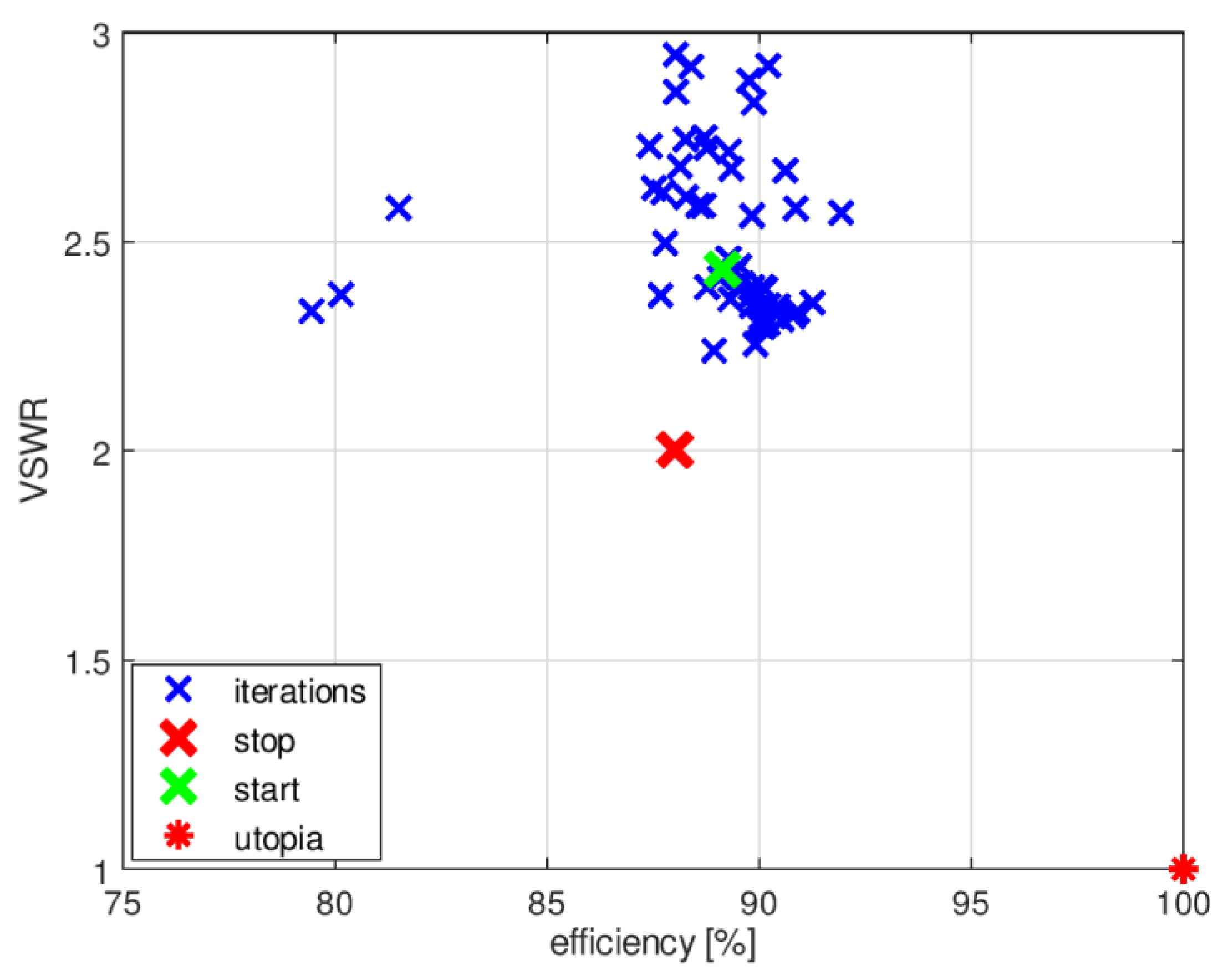
The history of the optimization process from the initial point (given in
Table 2) in the objective function space is presented in
Figure 8, where the utopia solution (the best combination of the objective function components) is marked by a red asterisk. The objective function components for the best solution identified by the algorithm were VSWR
stop = 2.43, RE
stop = 89%.
Figure 9 compares the impedance matching of the initial design with that following optimization with P-EStra.
To improve the impedance matching of the antenna in band 3, another run of the optimization algorithm was performed. In this case, the constraints were based on both the geometrical conditions and the objective function values. The constraints were considered as violated for a given set of design variables when the geometry was self-overlapping and when the VSWR value obtained for the proposed geometry was greater than 3. To test the second condition, it was necessary to run XFdtd, which increased the computational burden.
Figure 10 shows the history of the optimization process with VSWR limited constraints in the objective function space. The starting point was the same as final point in the previous optimization run.
In this case, the optimization algorithm needed 56 iterations to converge. Due to the need to estimate the value of VSWR for each set of design parameter values proposed by P-Estra, 24 more simulations were required using XFdtd. The objective function components for the best solution identified by algorithm were VSWR
stop = 2, RE
stop = 88%.
Table 3 presents the set of design parameters of the optimized antenna design and
Figure 11 the corresponding antenna geometry.
Figure 12 shows the impedance matching of the antenna optimized using P-EStra.
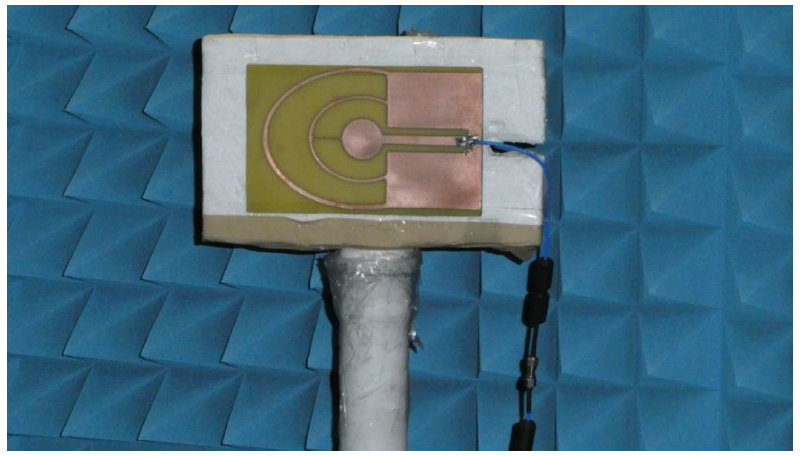
The impedance matching of the optimized antenna was verified experimentally using a prototype. The prototype antenna, fabricated on 1.5 mm thick FR4 substrate (ε = 4, tgδ = 0.01—these values are provided by the substrate manufacturer), is presented in
Figure 13. The impedance matching of the prototype antenna was measured using a Rohde & Schwarz ZVB 14 vector network analyzer in an anechoic chamber. Because the prototype antenna was fed by a coaxial probe, the calibration plane was moved to the end of the coaxial cable. The impedance matching of the prototype is presented in
Figure 14. The results obtained by means of measurements differ from the simulation results, but the character of VSWR parameter variation is similar. The greatest differences can be observed in band 2, where the maximum value for VSWR was 2.35 versus 2. In the other bands, the maximum VSWR was less than 2. Minor differences between the simulated impedance matching and the measurement results followed from the influence of the feeding of the prototype antenna which used a coaxial cable soldered directly to the printed antenna. In the numerical model of the antenna, the feeding source was connected directly between the internal rectangle and the outer rectangular part. The pieces of solder on the prototype antenna introduced additional volume of conductor detuning the antenna. Also, the limited precision of the prototype antenna geometry, which was fabricated using etching technology might introduce the small discrepancy between the results of simulations and measurements. The dielectric properties of the substrate used for the prototype may also have been different from those assumed during the optimization process.
5. Electromagnetic Characterization of the Optimized Antenna
The radiation properties of the antenna in different frequency bands depend on the electric current distribution along the antenna radiator. Analysis of this distribution was performed using Remcom XFdtd software. The antenna was fed with a harmonic signal of the middle frequency of each band (see
Table 1). The results are presented in
Table 4, in terms of surface current obtained for an antenna radiator surface normalized to 10 A/m. For band 1, the highest current density is on the feeding line edges and on the inner ellipse, while for higher bands it is on the feed line and on the inner circular part.
The fact that current distribution on the antenna surface varies with frequency results in a radiation pattern that also depends on frequency. The radiation patterns of the antenna are presented in
Table 5. The spatial orientation of the radiation patterns corresponds to the axis presented in
Figure 11. The polarization of the antenna is linear, parallel to the plane of the antenna radiator. For band 1, the antenna exhibits an omnidirectional (with ca. −2 dB variation) radiation pattern in the plane perpendicular to the antenna axis of symmetry (the
z-x plane) with the maximum gain of 1.3 dBi. For this band, the antenna provides the transceiver with a quasi-circular coverage, which is a desirable feature in mobile wireless systems in which the relative spatial placement of other terminals is not fixed. The distribution of antenna gain in the vertical plane (
z-y) with a null in the direction of the antenna axis of symmetry is typical of antennas for which currents flow predominantly in a vertically oriented conductor (dipole, monopole, UWB monopole antenna etc.).
For higher frequency bands, the antenna dimensions are comparable or greater than the wavelength. This results with the current distribution on the antenna surface which exhibits multiple local maxima. This results in greater variation of the antenna gain in the z-y plane, where side lobes are visible. Also in the z-x plane, the gain differs from the perfectly omnidirectional distribution within the range of 7 dB while the maximum gain increases up to 7.2 dBi. These radiation properties are suitable for the assumed communication scenario in which the antenna is a node component in a multiband wireless sensor network because the antenna gain in the z-y plane that is assumed to be in the horizontal plane is always greater than −4 dBi which is acceptable for multiband antennas. In the case of the indoor scenario, the local minima in the radiation pattern that are visible for higher bands are acceptable because of multipath propagation which compensates for the influence of the minima.
7. Conclusions
In this paper, we have presented a novel design for a four-band antenna to be used for multiband wireless sensor networks. The antenna is designed to operate effectively in two open frequency bands (ISM—Industrial, Scientific, Medical), 2.4 GHz and 5.8 GHz, as well as in two bands allocated for the fifth-generation (5G) cellular networks, 0.7 GHz and 3.5 GHz. We have demonstrated an effective method for bi-objective multi-parameter optimization of the antenna geometry, using the P-EStra algorithm. This algorithm was able to improve the complex geometry of our initial multiband antenna, which in the studied case was controlled by nine design parameters. We used a two-dimensional objective function and fully Paretian approach to optimize the antenna with respect to two design criteria (VSWR and radiation efficiency). These criteria each have an important influence on antenna performance. There is no inherent limitation that prevents our optimization methodology from including additional dimensions of the objective function.
Finally, we verified the performance of our optimized four-band antenna design experimentally. Comparison of measurement results with simulations for impedance matching and radiation patterns showed good agreement in all four frequency bands.


