Polar Grid Navigation Algorithm for Unmanned Underwater Vehicles

Abstract
:1. Introduction
2. Error Equations of the UUV in Polar Grid Navigation
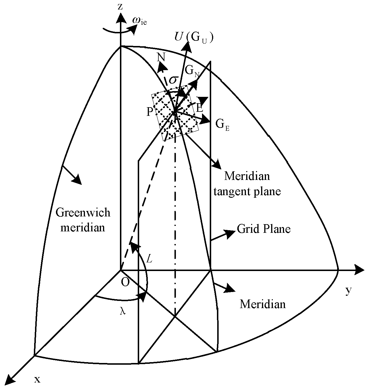
2.1. Grid Frame (G Frame)
2.2. Attitude Error Equation
2.3. Velocity Error Equation
2.4. Position Error Equation
2.5. Error Model of OCTANS
2.6. Error Model of DVL
3. Filter Models of the UUV in Polar Grid Navigation
3.1. Dynamic Model
3.2. Observation Model
4. Filter Algorithm of the UUV in Polar Grid Navigation
4.1. Modified Adaptive Kalman Filter
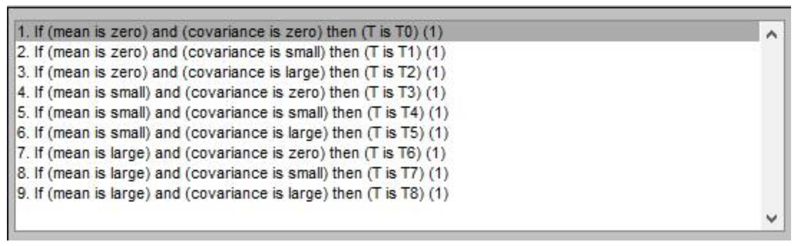
4.2. Fuzzy Inference System (FIS)
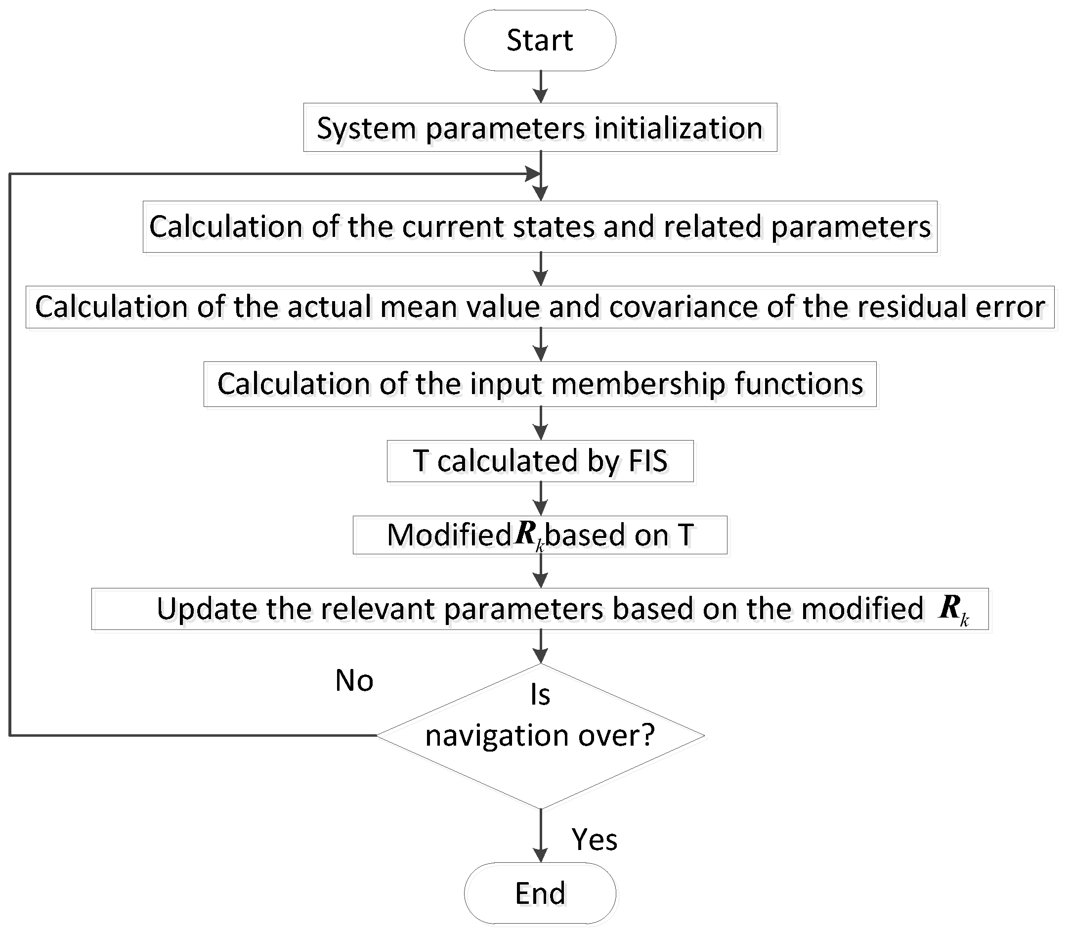
4.3. Modified FUZZY ADAPTIVE KALMAN Filter
5. Simulations and Experimental Results
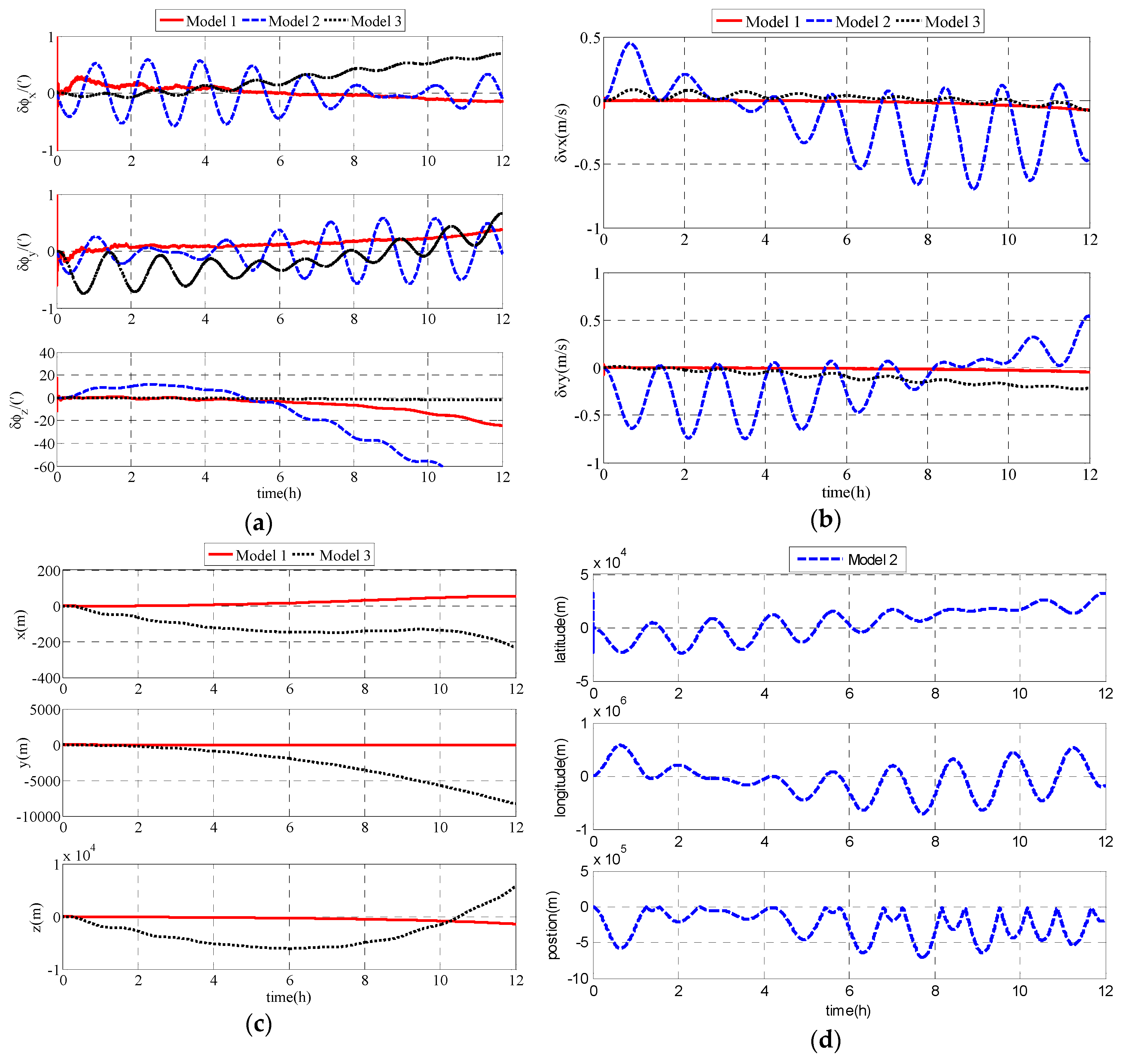
5.1. Simulation Results and Analysis
5.2. Experimental Results and Analysis
6. Discussion
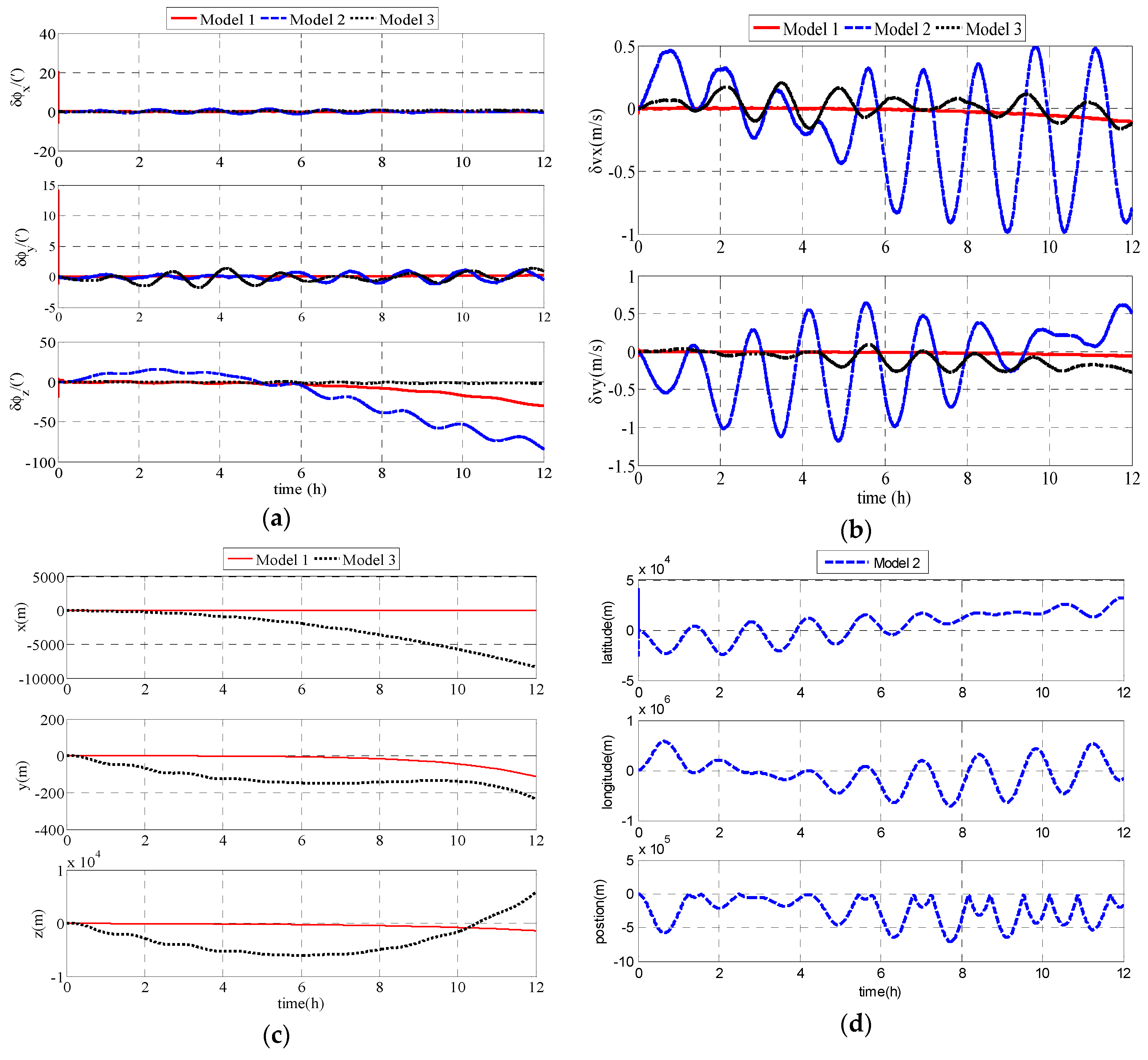
- SINS is widely used in UUV navigation because of its high autonomy. Model 2 is the typical SINS model for UUVs. It is a general model of SINS and can achieve a navigation accuracy that meets the requirements of UUVs in non-polar regions. While in the polar region, due to the rapid convergence of Earth meridians, there exist calculation overflows and sharply increasing errors in Model 2, in which the geographic frame is chosen as the navigation frame. This is because the error of the upside component of the command angular velocity is related to the tangent value of latitude in traditional SINS. In the polar region, the latitude tends to 90° and the error tends to infinity. Therefore, the geographic frame is not suitable to be chosen as the navigation frame in the polar region. To overcome the problems in the traditional SINS (Model 2) in the polar region, the transversal SINS (Model 3) and polar grid SINS (Model 1) are proposed. The transversal geographic frame and grid frame are chosen as the navigation frame to modify the unsuitability of the traditional SINS, respectively. Although the transversal SINS (Model 3) can realize navigation in the polar region, there are principle errors in the transversal SINS algorithm. The transversal SINS ignores the ellipse of the Earth. Model 1, based on the grid frame, is proposed to overcome the influence caused by the meridians’ convergence in high latitude areas. In the grid frame, the grid planes are parallel with the Greenwich plane. The polar region is the normal region in the polar grid navigation algorithm. There is no impact on the polar grid navigation. Simulation and experiment results also demonstrate that Model 1 is superior to Model 2 and Model 3 in accuracy. The polar grid navigation of UUVs proposed in this paper (Model 1) is suitable for UUV navigating in the polar region.
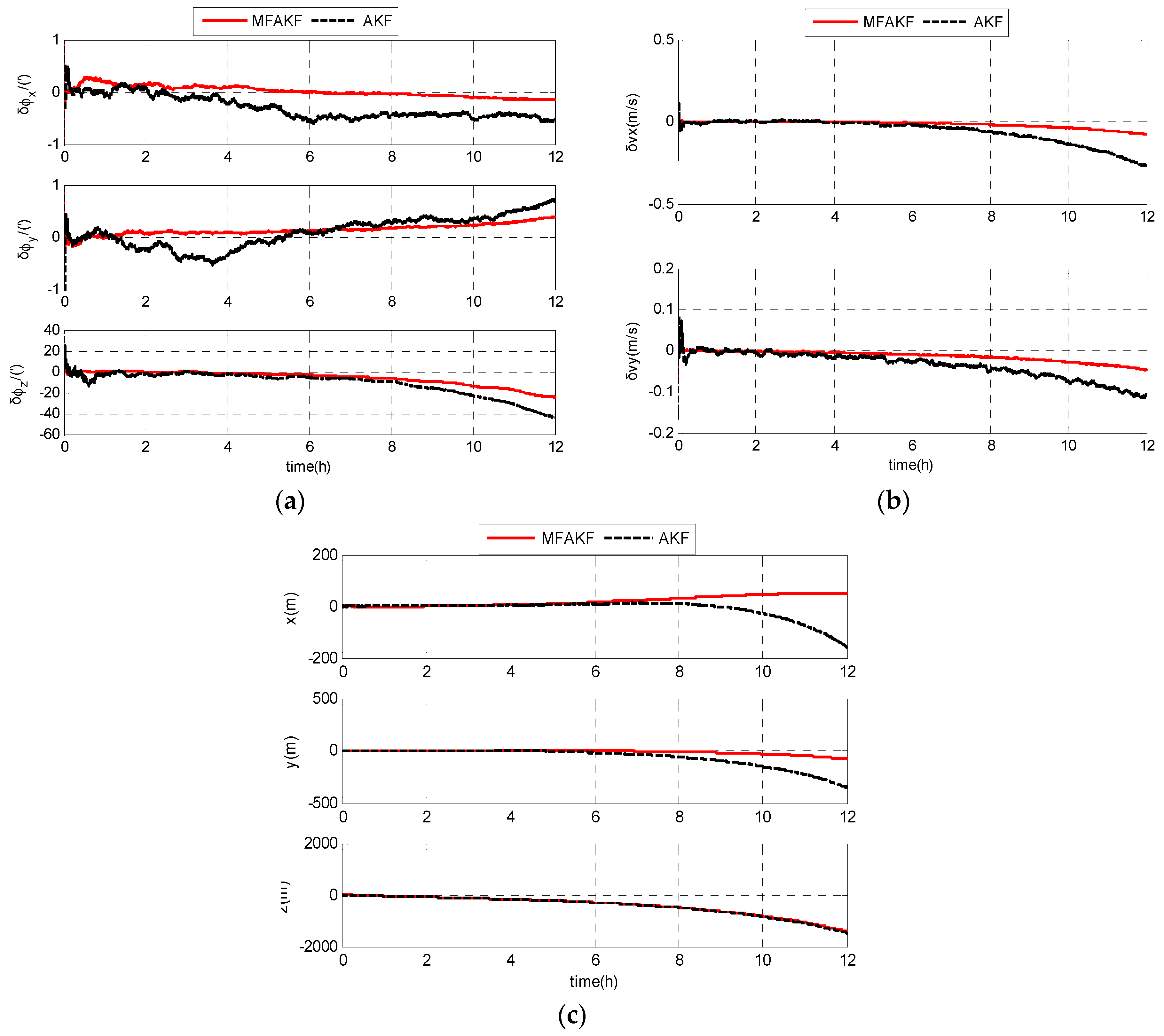
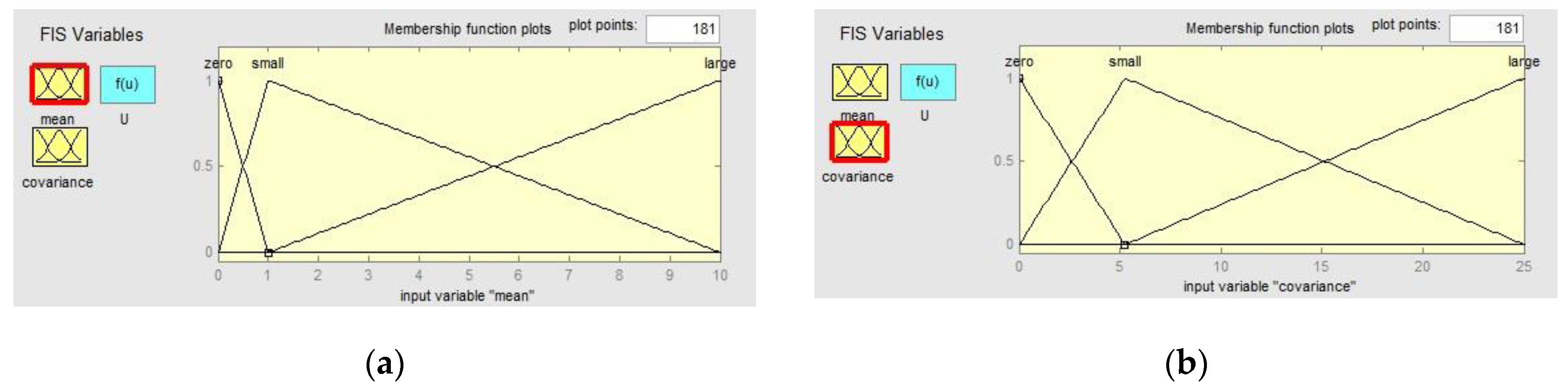
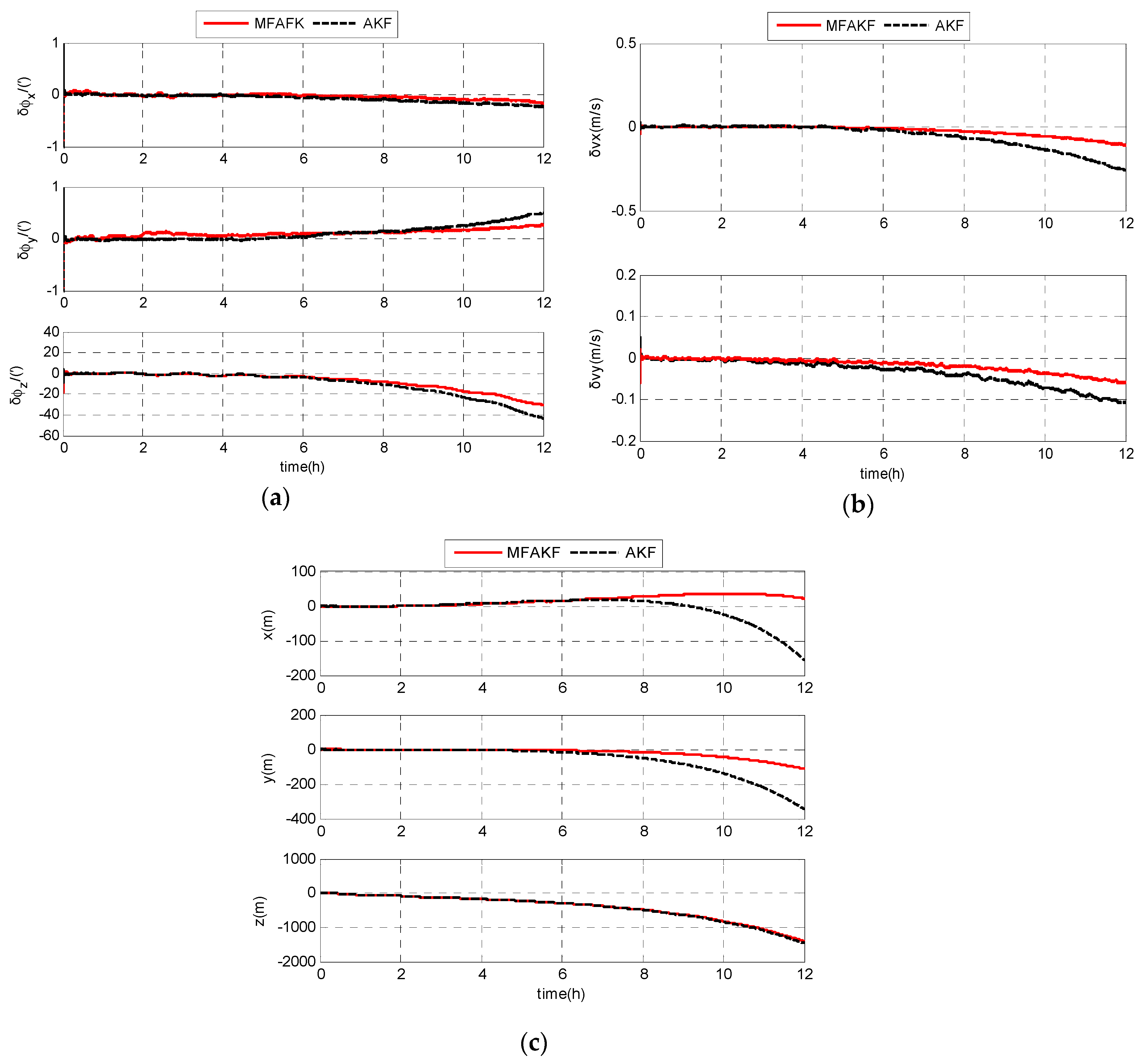
- Ignoring the negative terms can not only simplify the filter but can also keep the positive definiteness of the filter. T-S fuzzy logic regulates the residual error close to zero. The covariance is also regulated by FIS to adjust the changing of the environment. The adaptive Kalman filter will achieve the optimal state though the covariance modified by FIS. MFAKF can adjust the changing of the environment. Therefore, MFAKF is superior to AKF in estimating the states of filter.
7. Conclusions
Acknowledgments
Author Contributions
Conflicts of Interest
References
- Jacobi, M. Autonomous inspection of underwater structures. Robot. Auton. Syst. 2015, 67, 80–86. [Google Scholar] [CrossRef]
- Wynn, R.B.; Huvenne, V.A.I.; Le Bas, T.P.; Murton, B.J.; Connelly, D.P.; Bett, B.J.; Ruhl, H.A.; Morris, K.J.; Peakall, J.; Parsons, D.R.; et al. Autonomous Underwater Vehicles (AUVs): Their past, present and future contributions to the advancement of marine geoscience. Mar. Geol. 2014, 352, 451–468. [Google Scholar] [CrossRef]
- Sabet, M.T.; Sarhadi, P.; Zarini, M. Extended and Unscented Kalman filters for parameter estimation of an autonomous underwater vehicle. Ocean Eng. 2014, 91, 329–339. [Google Scholar] [CrossRef]
- Modalavalasa, N.; Rao, G.S.B.; Prasad, K.S.; Ganesh, L.; Kumar, M.N.V.S.S. A new method of target tracking by EKF using bearing and elevation measurements for underwater environment. Robot. Auton. Syst. 2015, 74, 221–228. [Google Scholar] [CrossRef]
- Allotta, B.; Caiti, A.; Chisci, L.; Costanzi, R.; Di Corato, F.; Fantacci, C.; Fenucci, D.; Meli, E.; Ridolfi, A. An unscented Kalman filter based navigation algorithm for autonomous underwater vehicles. J. Mechatron. 2016, 39, 185–195. [Google Scholar] [CrossRef]
- Allotta, B.; Caiti, A.; Costanzi, R.; Fanelli, F.; Fenucci, D.; Meli, E.; Ridolfi, A. A new AUV navigation system exploiting unscented Kalman filter. Ocean Eng. 2016, 113, 121–132. [Google Scholar] [CrossRef]
- Xu, B.; Bai, J.L.; Hao, Y.L.; Gao, W.; Liu, Y.L. The research status and progress of cooperative navigation for multiple AUVs. Acta Autom. Sin. 2015, 41, 445–461. (In Chinese) [Google Scholar] [CrossRef]
- Allotta, B.; Costanzi, R.; Meli, E.; Pugi, L.; Ridolfi, A.; Vettori, G. Cooperative localization of a team of AUVs by a tetrahedral configuration. Robot. Auton. Syst. 2014, 62, 1228–1237. [Google Scholar] [CrossRef]
- Fallon, M.F.; Papadopoulos, G.; Leonard, J.J. A measurement distribution frame work for cooperative navigation using multiple AUVs. In Proceedings of the 2010 IEEE International Conference on Robotics and Automation, Anchorage, AK, USA, 3–8 May 2010; pp. 4256–4263. [Google Scholar] [CrossRef]
- Anderson, E.W.I. Navigation in Polar Regions. J. Navig. 1957, 10, 156–161. [Google Scholar] [CrossRef]
- Dyer, G.C. Polar Navigation—A New Transverse Mercator Technique. J. Navig. 1957, 24, 484–495. [Google Scholar] [CrossRef]
- Liu, M.; Gao, Y.B.; Li, G.C.; Guang, X.X.; Li, S.T. An improved alignment method for the Strapdown Inertial Navigation System (SINS). Sensors 2016, 16, 621. [Google Scholar] [CrossRef] [PubMed]
- Li, Q.; Ben, Y.Y.; Yu, F.; Sun, F. System reset of transversal strapdown INS for ship in polar region. Measurement 2015, 60, 247–257. [Google Scholar] [CrossRef]
- Zhou, Q. All-Earth Inertial Navigation Algorithm for Large Aircraft. Northwest. Polytech. Univ. 2013, 10, 156–161. (In Chinese) [Google Scholar]
- Cheng, J.H.; Wang, T.D.; Guan, D.X.; Li, M.L. Polar transfer alignment of shipborne SINS with a large misalignment angle. Meas. Sci. Technol. 2016, 27, 035101. [Google Scholar] [CrossRef]
- Broxmeyer, C.; Leondes, C.I. Inertial navigation system. J. Appl. Mechan. 1964, 31, 735. [Google Scholar] [CrossRef]
- Huang, D.M.; Cheng, L. Inertial Navigation System; National Defense Industry Press: Beijing, China, 1978. [Google Scholar]
- Zhang, P.P.; Sun, Y.K.; Wang, H.B. Research on polar grid navigation of great-circle sailing. Command Control Simul. 2015, 37, 132–136. (In Chinese) [Google Scholar] [CrossRef]
- Zhang, H.F.; Zhang, L.W.; Wang, X.L.; Li, L.; Zhong, Y. Optimization design and error analysis of strapdown inertial navigation system mechanization in polar region. J. Chin. Inert. Technol. 2015, 23, 701–706. (In Chinese) [Google Scholar] [CrossRef]
- Zhou, Q.; Qin, Y.Y.; Fu, Q.W.; Yue, Y.Z. Grid mechanization in Inertial Navigation Systems for Transpolar Aircraft. J. Northwest. Polytech. Univ. 2013, 31, 210–217. (In Chinese) [Google Scholar]
- Farrell, J.; Barth, M. The Global Positioning System and Inertial Navigation; McGraw-Hill: New York, NY, USA, 1998; pp. 27–30. [Google Scholar]
- Thong, Y.K.; Woolfson, M.S.; Crowe, J.A.; Hayes-Gill, B.R.; Challis, R.E. Dependence of inertial measurements of distance on accelerometer noise. Meas. Sci. Technol. 2002, 13, 1163–1172. [Google Scholar] [CrossRef]
- Li, W.L.; Wang, J.L.; Lu, L.Q.; Wu, W.Q. A novel scheme for DVL-aided SINS in-motion alignment using UKF techniques. Sensors 2013, 13, 1046–1063. [Google Scholar] [CrossRef] [PubMed]
- Liu, X.X.; Xu, X.S.; Liu, Y.T.; Wang, L.H. Kalman filter for cross-noise in the integration of SINS and DVL. Math. Probl. Eng. 2014, 2014, 260209. [Google Scholar] [CrossRef]
- Bian, H.W.; Jin, Z.H.; Tian, W.F. Study on GPS attitude determination system aided INS using adaptive Kalman filter. Meas. Sci. Technol. 2005, 16, 2072–2079. [Google Scholar] [CrossRef]
- Sasiadek, J.Z.; Wang, Q.; Zeremba, M.B. Fuzzy adaptive Kalman filtering for INS/GPS data fusion. In Proceedings of the IEEE International Symposium on Intelligent Control, Rio Patras, Greece, 19 July 2000; pp. 181–186. [Google Scholar]
- Li, X. Fuzzy adaptive Kalman filter for wind power output smoothing with battery energy storage system. IET Renew. Power Gener. 2012, 6, 340–347. [Google Scholar] [CrossRef]
- Bai, J.; Liu, J.Y.; Yuan, X. Study of fuzzy adaptive Kalman filtering technique. Inf. Control 2002, 30, 193–197. (In Chinese) [Google Scholar]
- Wang, Q.Y.; Diao, M.; Gao, W.; Zhu, M.H.; Xiao, S. Integrated navigation method of a marine strapdown inertial navigation system using a star sensor. Meas. Sci. Technol. 2015, 26, 115101. [Google Scholar] [CrossRef]


| Parameters | MFAKF | AKF |
|---|---|---|
| /(′) | 0.0872 | 0.6117 |
| /(′) | 0.1429 | 0.2655 |
| /(′) | 9.0768 | 14.3786 |
| /(m/s) | 0.0256 | 0.0912 |
| /(m/s) | 0.0182 | 0.0464 |
| /(m) | 28.2271 | 37.9480 |
| /(m) | 22.7024 | 100.8459 |
| /(m) | 556.3639 | 573.4550 |
| Parameters | MFAKF | AKF |
|---|---|---|
| /(′) | 0.0571 | 0.0896 |
| /(′) | 0.1257 | 0.1601 |
| /(′) | 11.0893 | 15.1294 |
| /(m/s) | 0.0376 | 0.0909 |
| /(m/s) | 0.0241 | 0.0462 |
| /(m) | 21.3962 | 36.3067 |
| /(m) | 33.5115 | 103.3216 |
| /(m) | 551.6560 | 566.5706 |
© 2017 by the authors. Licensee MDPI, Basel, Switzerland. This article is an open access article distributed under the terms and conditions of the Creative Commons Attribution (CC BY) license (http://creativecommons.org/licenses/by/4.0/).
Share and Cite
Yan, Z.; Wang, L.; Zhang, W.; Zhou, J.; Wang, M. Polar Grid Navigation Algorithm for Unmanned Underwater Vehicles. Sensors 2017, 17, 1599. https://doi.org/10.3390/s17071599
Yan Z, Wang L, Zhang W, Zhou J, Wang M. Polar Grid Navigation Algorithm for Unmanned Underwater Vehicles. Sensors. 2017; 17(7):1599. https://doi.org/10.3390/s17071599
Chicago/Turabian StyleYan, Zheping, Lu Wang, Wei Zhang, Jiajia Zhou, and Man Wang. 2017. "Polar Grid Navigation Algorithm for Unmanned Underwater Vehicles" Sensors 17, no. 7: 1599. https://doi.org/10.3390/s17071599
APA StyleYan, Z., Wang, L., Zhang, W., Zhou, J., & Wang, M. (2017). Polar Grid Navigation Algorithm for Unmanned Underwater Vehicles. Sensors, 17(7), 1599. https://doi.org/10.3390/s17071599