You are currently viewing a new version of our website. To view the old version click .
Sensors
  • Article
  • Open Access

21 March 2017

An Electricity Price-Aware Open-Source Smart Socket for the Internet of Energy

,
,
and
Department Electronics and Systems, Faculty of Computer Science, Universidade da Coruña, 15071 A Coruña, Spain
*
Author to whom correspondence should be addressed.
This article belongs to the Special Issue State-of-the-Art Sensors Technology in Spain 2016

Abstract

The Internet of Energy (IoE) represents a novel paradigm where electrical power systems work cooperatively with smart devices to increase the visibility of energy consumption and create safer, cleaner and sustainable energy systems. The implementation of IoE services involves the use of multiple components, like embedded systems, power electronics or sensors, which are an essential part of the infrastructure dedicated to the generation and distribution energy and the one required by the final consumer. This article focuses on the latter and presents a smart socket system that collects the information about energy price and makes use of sensors and actuators to optimize home energy consumption according to the user preferences. Specifically, this article provides three main novel contributions. First, what to our knowledge is the first hardware prototype that manages in a practical real-world scenario the price values obtained from a public electricity operator is presented. The second contribution is related to the definition of a novel wireless sensor network communications protocol based on Wi-Fi that allows for creating an easy-to-deploy smart plug system that self-organizes and auto-configures to collect the sensed data, minimizing user intervention. Third, it is provided a thorough description of the design of one of the few open-source smart plug systems, including its communications architecture, the protocols implemented, the main sensing and actuation components and the most relevant pieces of the software. Moreover, with the aim of illustrating the capabilities of the smart plug system, the results of different experiments performed are shown. Such experiments evaluate in real-world scenarios the system’s ease of use, its communications range and its performance when using HTTPS. Finally, the economic savings are estimated for different appliances, concluding that, in the practical situation proposed, the smart plug system allows certain energy-demanding appliances to save almost €70 per year.

1. Introduction

The world has many reasons to make the transition to a clean energy economy. Collectively, greenhouse gas emissions must be decreased in order to reduce significantly the risks posed by climate change. Some of the most dangerous consequences include intensifying droughts, storms, heat waves, the inundation of coastal economies brought on by rising sea levels, acidifying oceans, increasing wildfires and extreme weather events across the world. Reducing fossils dependence, tackling global warming, strengthening energy security and, thus, improving our health are today’s main concerns. Governments have set ambitious goals regarding the increase of renewable energy production, energy savings and greenhouse gas emission reduction in 2030 EU Energy Strategy [1] and the intended nationally-determined contributions to the Paris agreement [2]. There is no doubt that energy production systems need to be changed, since today they rely heavily on oil, natural gas and coal for generation. Nevertheless, rather than focusing only on new sources for energy supply, reducing and optimizing the demand should also be explored, as it would bring similar benefits.
The remarkably rapid growth of inexpensive and tiny computing devices, endowed with augmented sensing and communication capabilities, is paving the way for a growing presence and use of smart devices under the Internet of Things (IoT) paradigm: the number of IoT devices is expected to exceed 30 billion by 2020. Such devices are prone to security issues [3]; they draw data from large-scale industrial assets and other equipment and will increase global energy consumption. Moreover, the rise of Industry 4.0 and Cyber-Physical Systems (CPS) [4] represent a windfall for the smarter grid, which will operate in combination with the Internet of Energy (IoE). IoE [5] changes the concept of energy infrastructure, which is increasingly becoming dynamic, effective, intelligent, responsive and interconnected. Consequently, it reveals a promising future for eco-smart practices [6], more intelligent infrastructures (e.g., homes [7] or buildings) and industrial sectors, like defense [8,9], where electrical power systems would work cooperatively with smart devices to increase the visibility of energy consumption and create safer, cleaner and more sustainable energy systems. IoE systems require the use of multiple software and hardware components like embedded systems, power electronics, integrated circuits, sensors, processing units or storage technologies. Such components are an essential part of the infrastructure of companies dedicated to the generation and distribution energy and the one required by the final consumer.
In Spain, new regulations about energy cost became effective on 1 April 2014 [10]. Such regulations indicate that consumers with a contracted power of less than 10 kW can opt for the Volunteer Price for the Small Consumer (Precio Voluntario para el Pequeño Consumidor (PVPC) in Spanish) [11]. In this new pricing system, the price of the energy depends on the moment when it is consumed and charges are applied through smart meters. The installation of such in-home smart meters also allows consumers to know in real time the cost of the electricity they are consuming. In this way, theoretically, the supply should be more stable, the production costs would be reduced and the risk of fail or blackout due to power overloads should decrease.
This article presents a smart socket system that makes use of sensors, actuators and wireless transceivers to collect the information about pricing and the user preferences and to optimize home energy consumption. The system collects daily the data on pricing published by Red Eléctrica de España (Spanish Electrical Grid) and analyzes them to determine the time intervals with the lowest prices.
To this end, an autoconfigurable easy-to-deploy system has been developed. It is based on a series of intelligent power outlets connected to each other through a shared Wi-Fi network. Such power outlets measure the current of the devices connected to them by means of current intensity sensors. The collected data are sent to a central control device to generate statistics and to perform actions depending on the data. To carry out these actions, each socket embeds a relay that acts as an actuator and may allow or deny the passage of current to an appliance according to the commands sent by the central control device.
Thanks to the distributed allocation of smart sockets, energy consumption can be collected easily and monitored through a user-friendly interface to improve price-aware decision-making. Specifically, the advanced IoT-based structures presented in this article interact with the surrounding environment in terms of sensing and metering, processing this information to extract knowledge for optimizing energy efficiency at the demand side. Therefore, this article shows the benefits and opportunities that IoT technologies can provide for IoE.
It is important to emphasize the three main contributions provided by this article:
  • It presents what to our knowledge is the first smart plug that manages in a real-world scenario the price values obtained from a public electricity operator to determine the time intervals with the lowest prices.
  • One of the few open-source smart plug systems described in the literature is detailed.
  • A novel wireless sensor network communications protocol based on Wi-Fi is presented that allows for creating an easy-to-deploy system that self-organizes and autoconfigures to minimize user intervention.
The remainder of this paper is organized as follows. Section 2 analyzes the latest academic and commercial smart power outlets. Section 3 details the design of the system proposed. Section 4 describes the communications architecture and the protocols implemented. Section 5 enumerates and gives details on the components of the system. Section 6 describes the most relevant elements of the software implemented. Section 7 details the experimental setup and the tests performed. Finally, Section 8 is devoted to the conclusions.

3. Design of the System

The system proposed in this paper allows for monitoring in real time the consumption of each connected device and storing the historical consumption values. Additionally, it makes it possible to remotely control the switching off and on of each of the power outlets and to plan the period of operation of each appliance in the most appropriate time slots to minimize the cost of energy consumption based on the daily price data.
The system takes advantage of the fact that many appliances have some flexibility about when they should operate. For example, a user generally does not care when the washing machine works as long as the task is performed for a limited period of time and the laundry is ready before a time limit. Taking these parameters into account together with the hourly cost of energy, the system proposed can coordinate all of the devices to operate within the user’s preference ranges, selecting automatically the operation instants so that cost is minimized. The smart socket system is composed of the following subsystems, which are depicted in Figure 1:
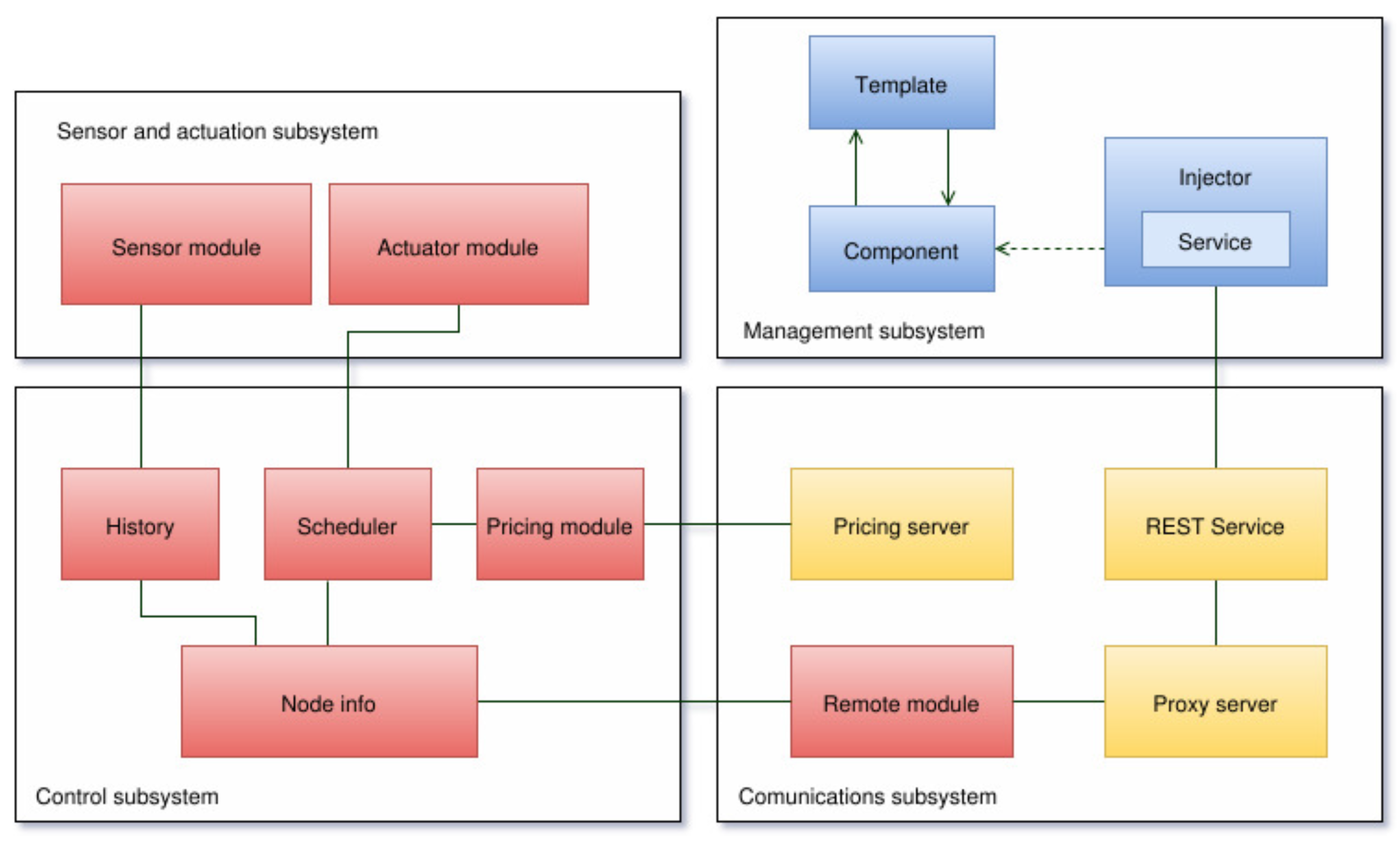
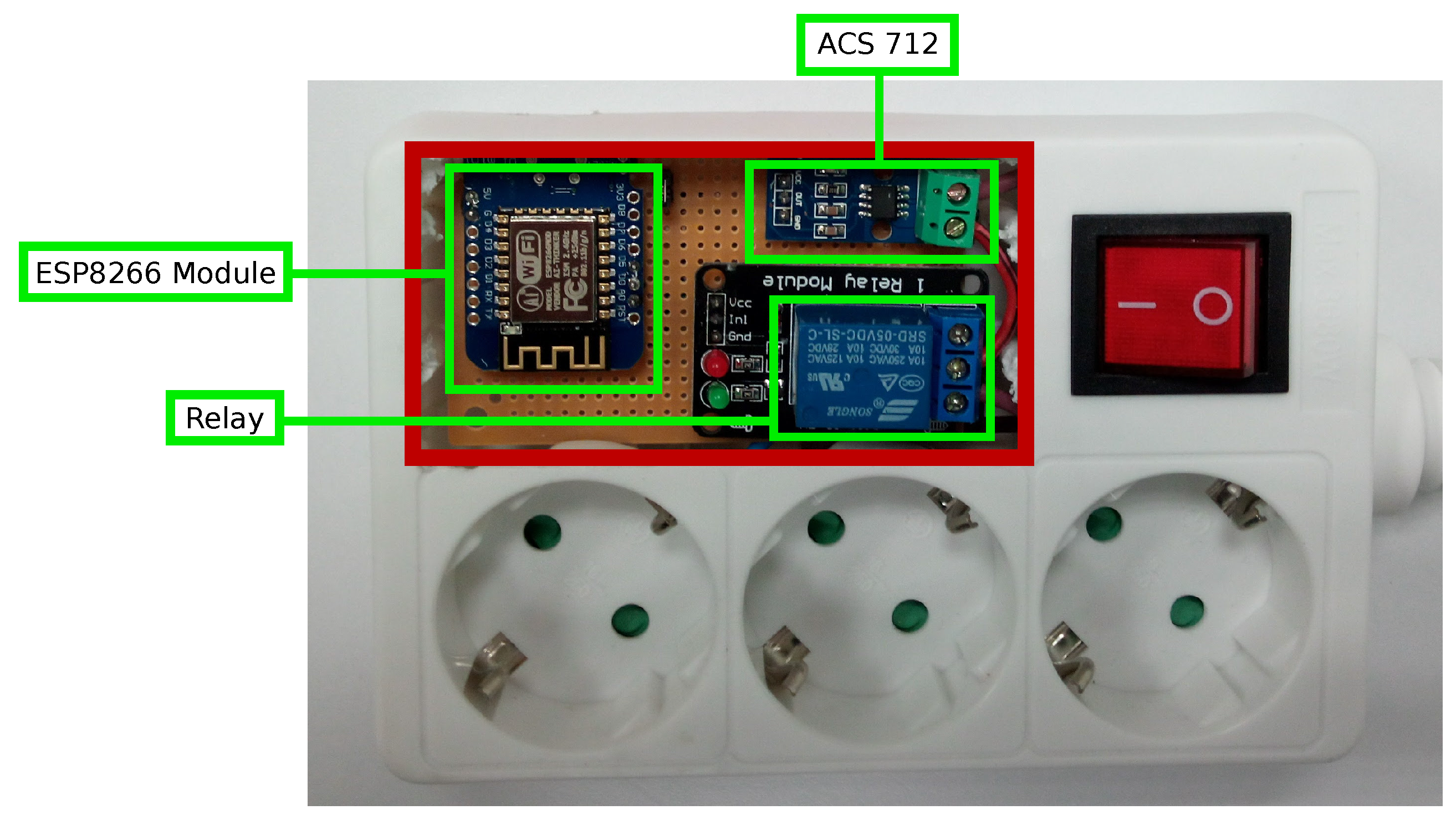
  • Sensor and actuation subsystem: This controls the sensors and actuators of the system. Such elements consist mainly of a current sensor and a relay. The subsystem is responsible for collecting current data and for activating the power outlet when it receives a request from the control subsystem.
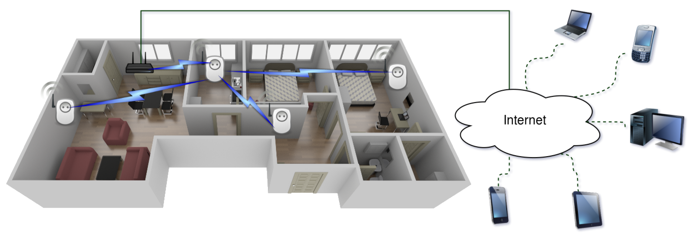
  • Communications subsystem: This consists of wireless transceivers that join an auto-configurable star topology.
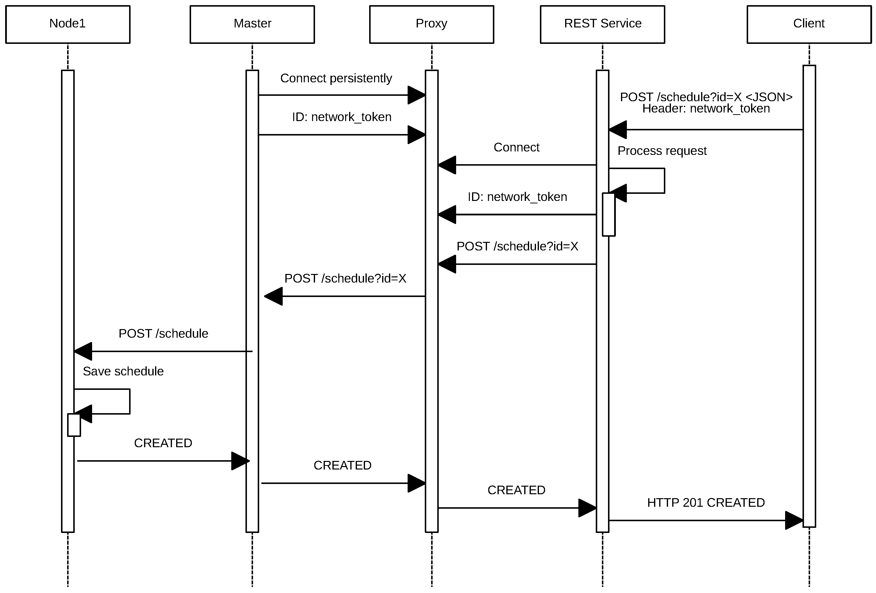
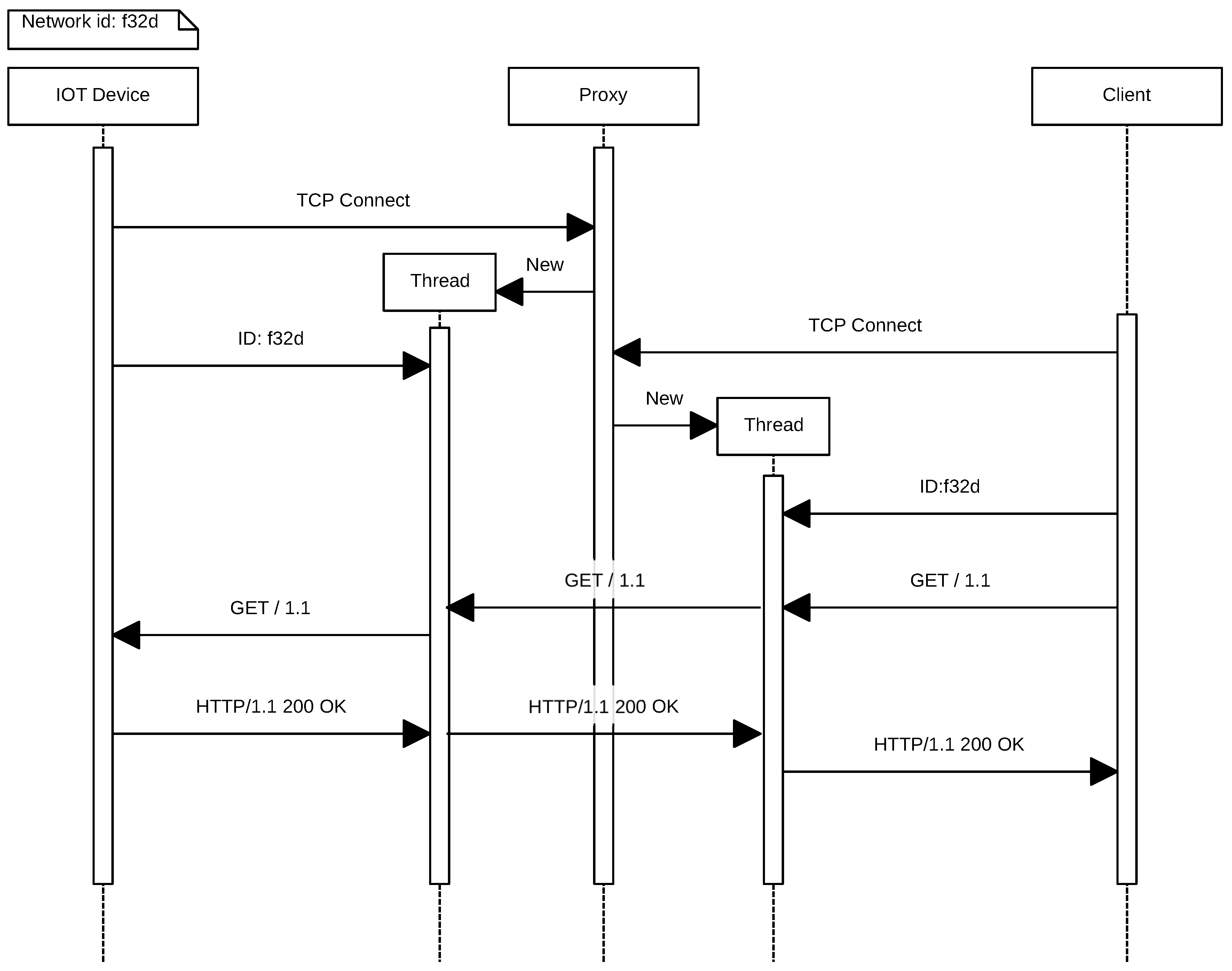
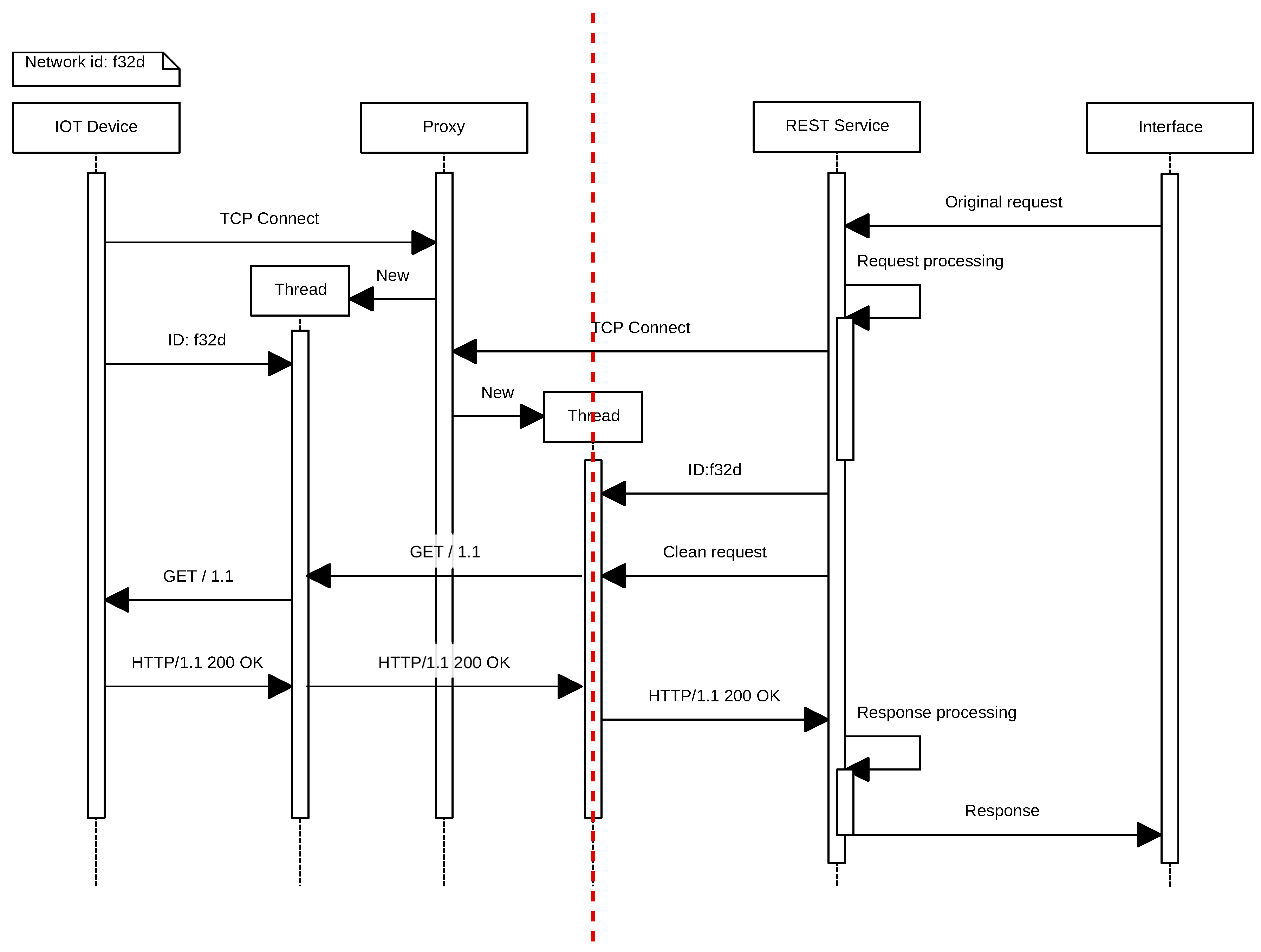
  • Management subsystem: This provides the user with the possibility of obtaining the current status of all modules, modifying their configuration and acting directly on them remotely through a web interface. In addition, this subsystem also includes a Representational State Transfer (REST) API that is responsible for transforming and redirecting the requests and responses between the clients and the corresponding device network through a proxy server.
  • Control subsystem: This is in charge of controlling and managing the remaining subsystems, registering all existing nodes in the network, processing the data through the appropriate scheduling algorithms in each case and sending the necessary information to each of the modules. In addition, it acts as the gateway of the network to connect to the Internet, and therefore, it is the entry point to the network for the management subsystem.
Figure 1. Subsystems diagram.

3.1. Electricity Pricing in Spain

From April 2014 onwards, Volunteer Price for the Small Consumer (PVPC) is the electricity price-setting system that has been introduced by the Spanish Government in the regulated market. It is applied to the electricity bill of those consumers whose contracted power does not exceed 10 kW.
The PVPC system modifies the method for calculating the price of producing electricity. Consumers pay for their consumption, over a billing period, an hourly price obtained in the electricity intraday market. Thus, the computation of the new prices is performed by calculating the cost of energy production based on the day-ahead, along with other concepts established in the new methodology approved by the government as established in regulation RD 216/2014 of 28 March [10].
Red Eléctrica de España (REE) is the operator of the Spanish electricity grid and informs citizens by providing a tool to help them to manage their power consumption more efficiently. Everyday, around 8:15 p.m., REE publishes on its website the electricity pricing schedule that will be applied in each of the 24 h of the following day. Those consumers who have installed a smart meter, which is able to measure current by the hour, have these new prices applied to their bill in accordance with their consumption throughout the day. Therefore, the information regarding hourly pricing schedules allows consumers with a smart meter to adjust their bill if they adapt their electricity consumption to the time slots when electricity is cheaper. Note that in Spain by 2018, 100% of residential consumers will have a smart meter installed, so hourly prices will be applied to the 16.2 million users who are covered by PVPC (60% of the nearly 27 million electricity supply contracts that are currently signed in Spain).

3.2. PVPC Bill Calculation

The invoicing of the PVPC is composed by the sum of the following billing terms related to power, active energy and passive energy:
  • The annual power billing FPU is calculated as the product of the power consumed ( P o t expressed in kW) and the price of the power for the PVPC ( T P U , expressed in euros/KW and year), according to the following equation:
    F P U = T P U × P o t
  • The active energy billing term for the corresponding billing period, F E U , is the result of multiplying the energy consumed during the billing period in each tariff period and the price of the corresponding energy term according to the following formulas: In the case of using an smart meter, the formula corresponds to:
    F E U = b i l l i n g p e r i o d ( E p × T E U p ) + h p ( E p h × T C U h )
    where:
    E p is the energy consumed during the billing period p (in kWh).
    E p h is the energy consumed during the hour h of the billing period p (expressed in kWh).
    T E U p represents the price of the energy term of the PVPC of the billing period p (in euros/kWh).
    T C U h is the term of the hourly cost of energy of PVPC for each hour h (in euros/kWh).
    Without a smart meter, the formula corresponds to:
    F E U = b i l l i n g p e r i o d E p × T E U p + h p ( T C U h × c h ) h p c h
    where c h is the hourly coefficient of the adjusted consumption profile. Every week, REE calculates and publishes the coefficients for the following week.
  • The conditions established for the application of the reactive energy billing term, as well as the obligations related to it, are established in regulation RD 1164/2001 of 26 October 2001 and determine the access tariff for the electricity transmission and for the distribution networks.
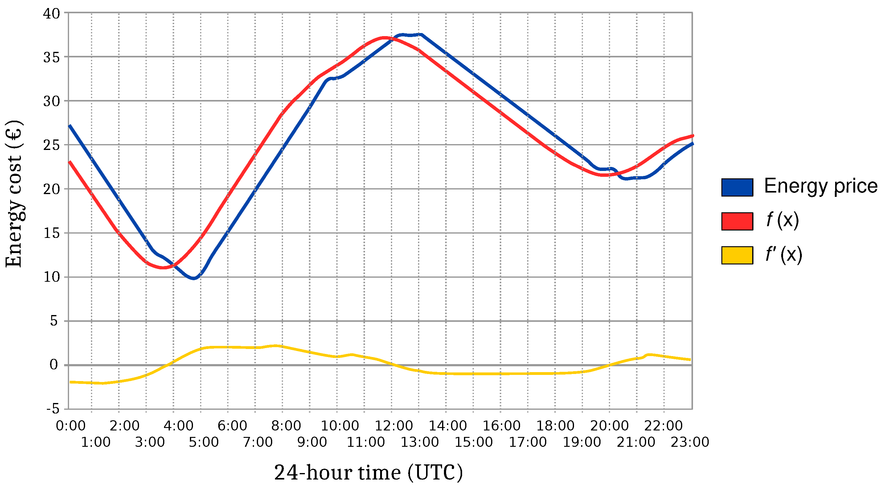
3.3. Minimizing FEU

FEU (the active energy billing term) can be optimized if the consumer has a contract whose electricity consumption can be adapted to the time slots during the day when electricity is cheaper. For such a purpose, a software module was designed aimed at finding the optimum operating instant for a given time interval so that the active energy billing term is minimized.
To obtain such a time instant, the energy cost function f(x) has to be determined by obtaining the pricing data from Red Eléctrica de España (REE) [66], and then, Equation (4) has to be minimized. In such an equation, an integral is defined between t and t + d, where t is the first time instant when the electrical device monitored is switched on and d is its operating time. Note in addition that t and t + d must belong to the interval.
T o t a l E n e r g y C o s t = t t + d f ( x ) d x t , t + d i n t e r v a l
Assuming that the blue line in Figure 2 represents the cost of energy in a given time interval and considering a time interval of two hours, if the integral defined between t and t + d is calculated, with d = 2 and t unknown, the function f ( x ) represented by the red line is obtained. This new function represents the energy cost of switching the device on for a period of 2 h at each of the time instants.
Figure 2. Example of the evolution of the energy prices during a specific time interval.
To find the optimal value, the value of t that minimizes f ( x ) has to be calculated. Note that the minimums and maximums of f ( x ) occur at points where the tangent to the function is horizontal. That is, the derivative f ( x ) is zero at points x at which f ( x ) is maximized or minimized. Thus, the yellow line in Figure 2 represents f ( x ) , and it can be observed that it is equal to zero at three critical points around 3:30, 12:00 and 20:00. Analyzing f ( x ) , it can be easily determined that the minimum is around 3:30.
The implementation presented in this paper follows the minimization steps previously described, but since f ( x ) is discrete, obtaining the minimum with a simple search is direct, and therefore, it is not necessary to calculate the first derivative.

4. Communications Protocol and Architecture

In Figure 3 is represented the communications architecture of the system proposed. The system distinguishes between two networks: an internal home network where smart plugs communicate with each other and an external network that allows remote users to access the internal network. Between both networks, there is a gateway that translates the external IP-based protocol to the internal ad hoc protocol. The next subsections describe how such protocols work and the inner workings of the communications architecture.
Figure 3. General overview of the system.

4.1. IoT Network

The IoT network is composed of nodes that connect to each other forming a star network topology, the central node being the one responsible for connecting to the gateway, which sends the data to the Internet.
Such a central node is designated as the master in the first phase of the negotiation for building the IoT network. All of the nodes that constitute the network have the ability to change their role and act as masters when required. However, the network self-manages to ensure that, at a specific time instant, only one of the nodes acts as the master. Thus, all nodes initially act as access points of a Wi-Fi network that allows for configuring each node individually and for discovering other nodes during the negotiation process of the network.
During the selection process of the master node, all nodes scan the network and compare the hardware identifiers of each device. Because such identifiers are assigned during manufacturing, it can be guaranteed that they are unique. When a node is powered up, it identifies all of the devices in the network with lower IDs and tries to communicate with them. Additionally, the device with the lowest ID changes its role to master and begins accepting connections from slaves. If after a certain number of attempts, it is not possible to establish a communication with the master node, the next device with the lowest ID is set automatically as the master until an agreement is reached. Once the negotiation has finished and the master is selected, all of the slaves connect to the Wi-Fi network offered by the master.
From this moment on, all communications between master and slaves will be carried out using HTTP. Thus, all nodes implement a lightweight HTTP server and an HTTP client. Although all modules were designed to support encryption using HTTPS, at this development stage of the prototype, all communications are performed in plain text to make debugging easier and to reduce development time. However, several tests were performed in order to assess the feasibility of using HTTPS (in Section 7.7), which would be essential in a final product.

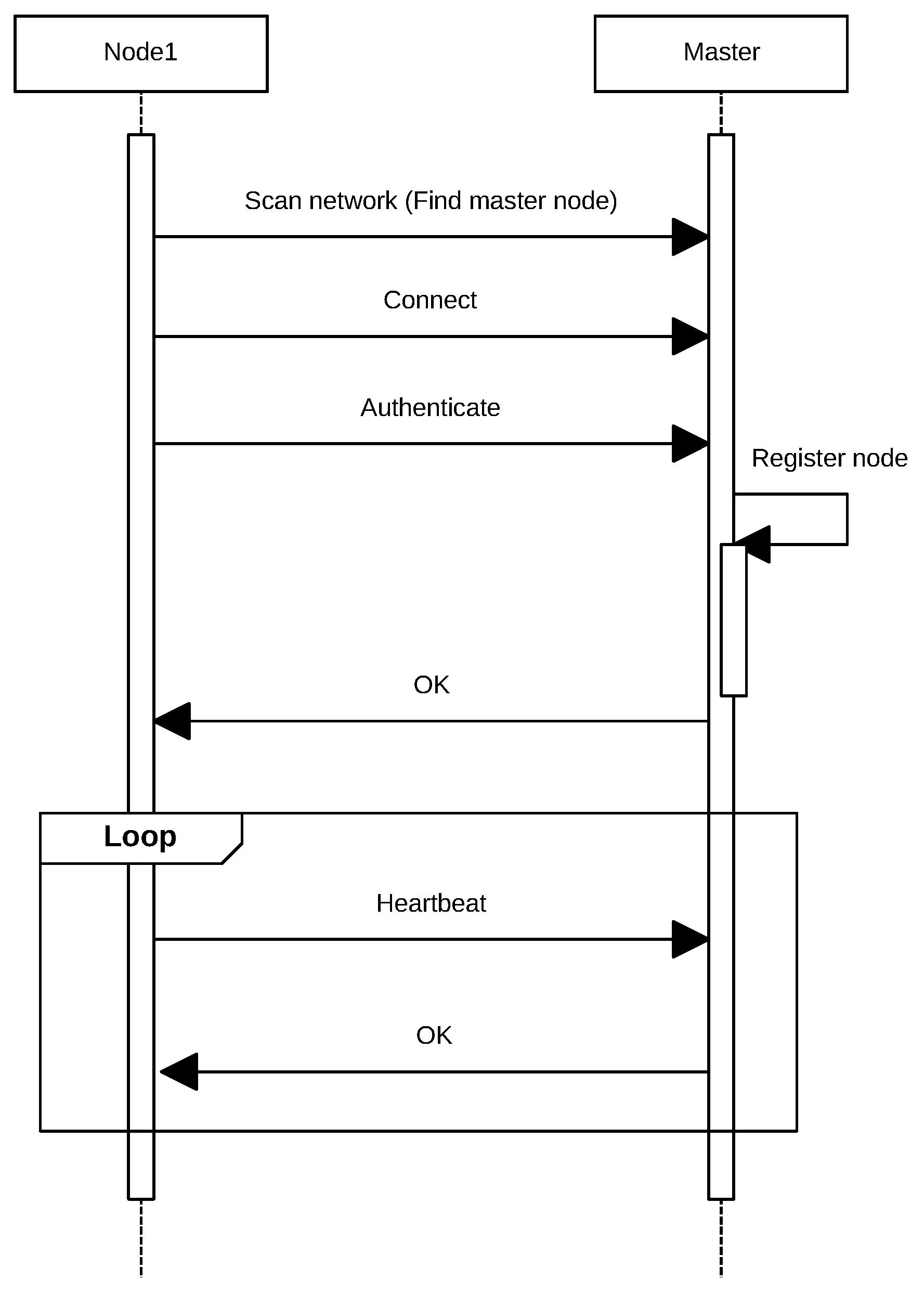
4.1.1. Keeping the Node List Updated

All slave nodes report their status to the master by sending periodically a POST request (heartbeat) as illustrated in Figure 4. This process allows for keeping the list of available nodes updated.
Figure 4. Sequence diagram for adding a new node.
With each heartbeat received, the master stores the ID of the node that sent the POST request and its IP. This information will be used to route incoming requests from the external network. If a node does not send heartbeats during a certain amount of time, the master considers that it is no longer available and deletes it from the list.

4.1.2. Clock Synchronization

The system proposed is based on creating an optimized energy consumption scheduling; therefore, it is essential that all nodes are synchronized and share the same time reference. To do this, the master node implements a Network Time Protocol (NTP) client that allows it to obtain the network time from an external server. The master node checks the time when it is initialized and at least once a day to make sure the network has the correct time. Regarding the slave nodes, they ask the master for the time periodically through HTTP requests. All nodes store operating intervals when they must be turned on for a certain duration. Figure 5 illustrates the process of adding an operation interval to a slave node. Slaves obtain the time instant in which the cost is minimized by asking the master node, which is responsible for applying the scheduling algorithm.
Figure 5. Sequence diagram for adding an operation interval.

4.2. External Network

With respect to the external network, it is necessary to be able to send requests from the Internet into the IoT network, taking into account that it may be protected behind a firewall that prevents incoming connections or that the nodes may be in an NATnetwork. The solution proposed to solve this issue is illustrated in the sequence diagram shown in Figure 6. Such a solution consists of implementing a server that acts as a proxy and that stores persistent connections from the masters of each network. Thus, using an ad hoc protocol, the system can forward client requests to one of the open connections on the server and thus penetrate the target network. To achieve such a goal, a REST service converts HTTP requests so that they can be sent through the proxy, which translates them into the format of the ad hoc protocol previously mentioned.
Figure 6. Sequence diagram that illustrates the tasks performed by the proxy server.
It can be also observed in Figure 6 that the process begins when an IoT device opens a permanent connection to the proxy and authenticates indicating its ID (in this case, f32d). Then, the remote client opens a connection to the proxy server and authenticates with the same node ID (i.e., f32d). From this moment on, the remote client is able to send HTTP requests to the IoT device. Note that, instead of an HTTP request, any other type of protocol could be used. At this point, in the example described, the IoT node would receive the GET request, and it would send back the response.

4.3. REST Web Service

In order to integrate the system easily with data visualization applications, it was decided to implement an REST web service that is responsible for translating HTTP REST requests to the internal protocol to communicate them through the proxy. This service allows for integrating web/mobile/desktop applications without the need for implementing a specific protocol for each one of them.
In addition, this service is responsible for cleanup requests, acting as the first filter before the data enter the IoT network, thus removing headers that are not strictly necessary and that would increase the computational load of the IoT devices (i.e., they would increase energy consumption and would slow down the processing).
Since the REST service is completely separated from the proxy server, it is easy to maintain it. The service also gives the user the flexibility to connect third-party developments to the system, and it could be even used to interconnect nodes of networks located in different network segments.
Figure 7 shows an example of the GET request processed by the service. Such a request was sent by a web client (in this case, PostMan [67]). As can be observed, the request is very verbose, and most of the information received is not useful for the IoT network. In fact, in this case, it is counterproductive, because it will force the IoT device to process a much larger amount of data, and because it is an integrated device with a limited computational capacity, it would lead to a considerable increase in response time. Therefore, the first action to be performed is to clean the request and forward only those data that will be relevant to the IoT device. The request, once filtered by the REST service, would look like the one shown in Figure 8. In Figure 9, the actual flow of the process previously described can be observed in the form of a sequence diagram.
Figure 7. HTTP GET request.
Figure 8. Optimized request.
Figure 9. Sequence diagram that illustrates the tasks carried out by the REST service.

5. Components of the System

As can be observed in Figure 10, each node of the IoT network consists basically of an ESP8266 module, a relay that allows for activating or deactivating the current flow, and an alternating current sensor that collects data of the power consumed by the smart power outlet. Furthermore, each node has a 230 V–5 V transformer able to use up to 700 mA, enough for powering up the ESP8266 (it may consume up to 240 mA), relay (72 mA) and the current sensor (10 mA).
Figure 10. Components of the smart socket system.
The ESP8266 module acts as a control and communications subsystem. It is responsible for sending and receiving data from other nodes and for performing actions on sensors and actuators. In addition, one of the nodes in the network is automatically configured as the master, so it will perform control and planning tasks on the network.
As was previously illustrated in Figure 1, all of these components are grouped into different subsystems, which are detailed in the next subsections.

5.1. Sensor and Actuation Subsystem

5.1.1. Current Sensor

This sensor detects the current flowing through a conductive element and generates a signal proportional to such a flow. The signal may consist of an analog voltage, an electric current or a digitally-encoded output. There are mainly four different types of current sensors: the ones based on Ohm’s law, sensors based on Faraday’s law, magnetic field-based sensors and Faraday-effect sensors [68]. A Hall-effect current sensor was chosen that met the specifications of the power outlet. Since the power outlet system was conceived of for small loads in home automation environments, the maximum power was established in 2000 W. Therefore, in a 230 V AC system (actually, in the Spanish regulations, it is 230 V ± 7%, so the voltage can reach almost 250 V), the limiting current will be approximately 8.127 A. Moreover, it is important to take into account that the control circuit that carries out the current measurements is operated at 5 V. Furthermore, for safety reasons, it is essential to insulate the 230 V-operated power circuit from the control circuit.
Among the different current sensors on the market, the Allegro ACS712-20AT was selected [69]. Such a sensor is powered with 5 V; it tolerates a maximum current of up to 30 A; it has a low energy consumption (10 mA) and a low cost (around $5, as of writing). In order to obtain with the sensor the effective value of the current flowing through a circuit, the mean squared value of the signal obtained at a time instant t has to be computed, which is proportional to the input current flow. For such a computation, the sensor signal has to be sampled during an interval T, as is shown in Equation (5), where t 0 is the time instant when sampling begins.
U e f = 1 T t 0 t 0 + T i 2 ( t ) d t

5.1.2. Relay

A relay is an electrical switch that allows for controlling, through a low-voltage circuit, a circuit of greater voltage, keeping them completely insulated electrically. Among all of the different types and models, a Songle SRD5V [70] was selected for the implementation described in this paper. It tolerates the maximum power established (2000 W); its control voltage is 5 V; and it has low-coil power consumption (360 mW) and a low-price (around $0.30 as of writing).

5.2. Control and Communications Subsystem

Sensors and actuators require an element to control them. Such an element has to be also responsible for collecting the data and for communicating with the other nodes of the system. For such tasks, a microcontroller gives a good trade-off between features and energy consumption.
Among all of the possible alternatives, it was decided to use the ESP8266 [71]. Specifically, during development a NodeMCU V1.0 board was used [72], while for the final assembly, a WeMos D1 Mini [73] was integrated in a power strip. Both boards use basically the same hardware and software, but the WeMos allows for reducing the form-factor of the prototype.
NodeMCU boards are really inexpensive (around $5, as of writing) and are as powerful as the other solutions analyzed. Since Wi-Fi is completely integrated on the board, no external shields or antennas are required. NoceMCU V1.0 contains a high-performance low-energy consumption module designed to be integrated in mobile developments. The module implements a full TCP/IP stack and offers wireless connectivity to other devices. Specifically, the module contains an ESP8266 System-on-Chip (SoC) from Espressif Systems [74] that has a 32-bit Tensilica LX106 Diamond Series processor at 80 MHz, with 50 KB of SRAM and 4 MB of flash memory. According to the manufacturer, 20% of the MIPS are used by the wireless protocol stack, while the rest is available for user applications.
ESP8266 modules are sold with a pre-installed firmware that receives AT commands through a serial port and that allows for performing basic configuration operations to use the module as a wireless connectivity interface for other devices. However, users can overwrite the flash memory with their own programs to perform more advanced operations.
Due to the low cost and the possibilities offered by this module, a large community of users has been created around it, and a multitude of free firmwares have been developed in order to extend the predetermined commands. Moreover, the community has developed environments based on the Arduino software to facilitate the programming of new firmware and to upload them into the flash memory of the device [75].

5.3. System Integration

In the final assembly of the prototype, a modified five-way square power strip was used. Removing two of the power outlets leaves enough space for putting the assembly of all of the components of the module safely. Figure 11 shows the different components inside the power strip. As was mentioned previously, in order to reduce the size of the prototype, the NodeMCU board was replaced with a WeMos D1 Mini board, since both are almost identical in terms of features, but the WeMos is packaged in a more compact form-factor.
Figure 11. Final assembly and main components of the smart power outlet.

6. Implementation

6.1. Implemented Functionality

As was previously mentioned, the main functionality of the system proposed is based on its ability to obtain the hourly cost data from the REE Application Programming Interface (API) [76] in order to carry out a planning to switch on and off the power outlets at the time instants with less economic cost. In addition, the system is able to be configured remotely to change the working mode of each of the nodes; add, modify or delete periods of operation; and remotely power on and off on demand. For performing such tasks, the following functions were implemented:
  • It allows for the configuration of each individual module in order to modify the network parameters or to add new nodes to an already existing network.
  • Once a node is added to a specific network, such a network is able to self-reconfigure and self-manage automatically with the objective of providing network communications to the added node.
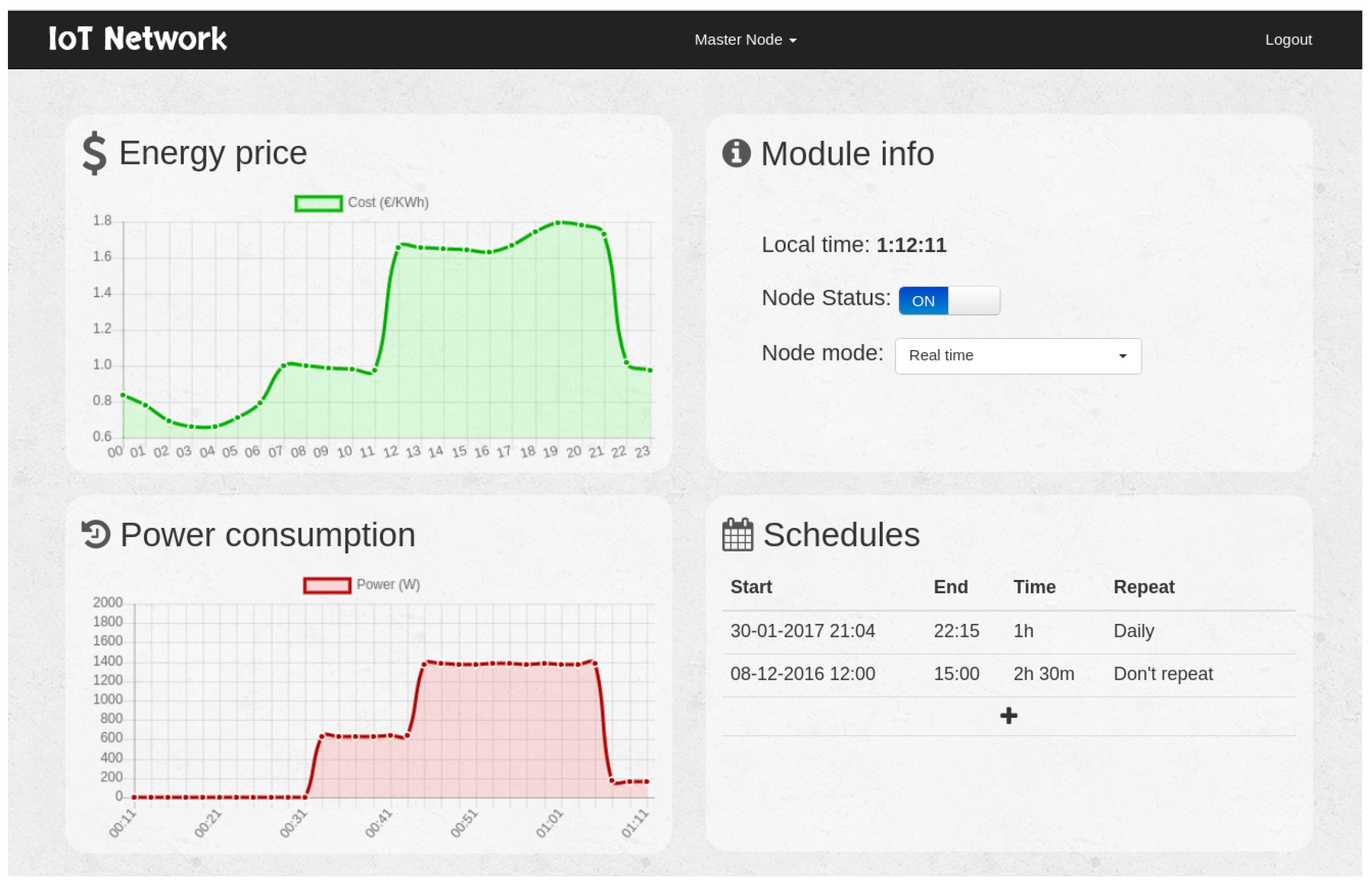
  • It obtains automatically and on a daily basis the electricity price by using the REE API. The system also shows in real time the cost of the energy.
  • The system is able to switch on and off every node of the IoT network in real time. It also shows the state of every power outlet in the network.
  • The user can visualize remotely the historical energy consumption values of every IoT node.
  • A user can change remotely the operation mode (i.e., manual or intelligent operation) of each power outlet. In intelligent mode, the system automatically switches on and off a node according to the time intervals that minimize the electricity cost.
  • The user can define, show and modify the operation intervals for every power outlet.
  • The system can be accessed from remote networks (i.e., from the Internet), being able to work behind a router that uses NAT without requiring additional configuration from the user.
  • A REST API was implemented to offer access to the system to third parties, who can interact dynamically with it and develop new applications.

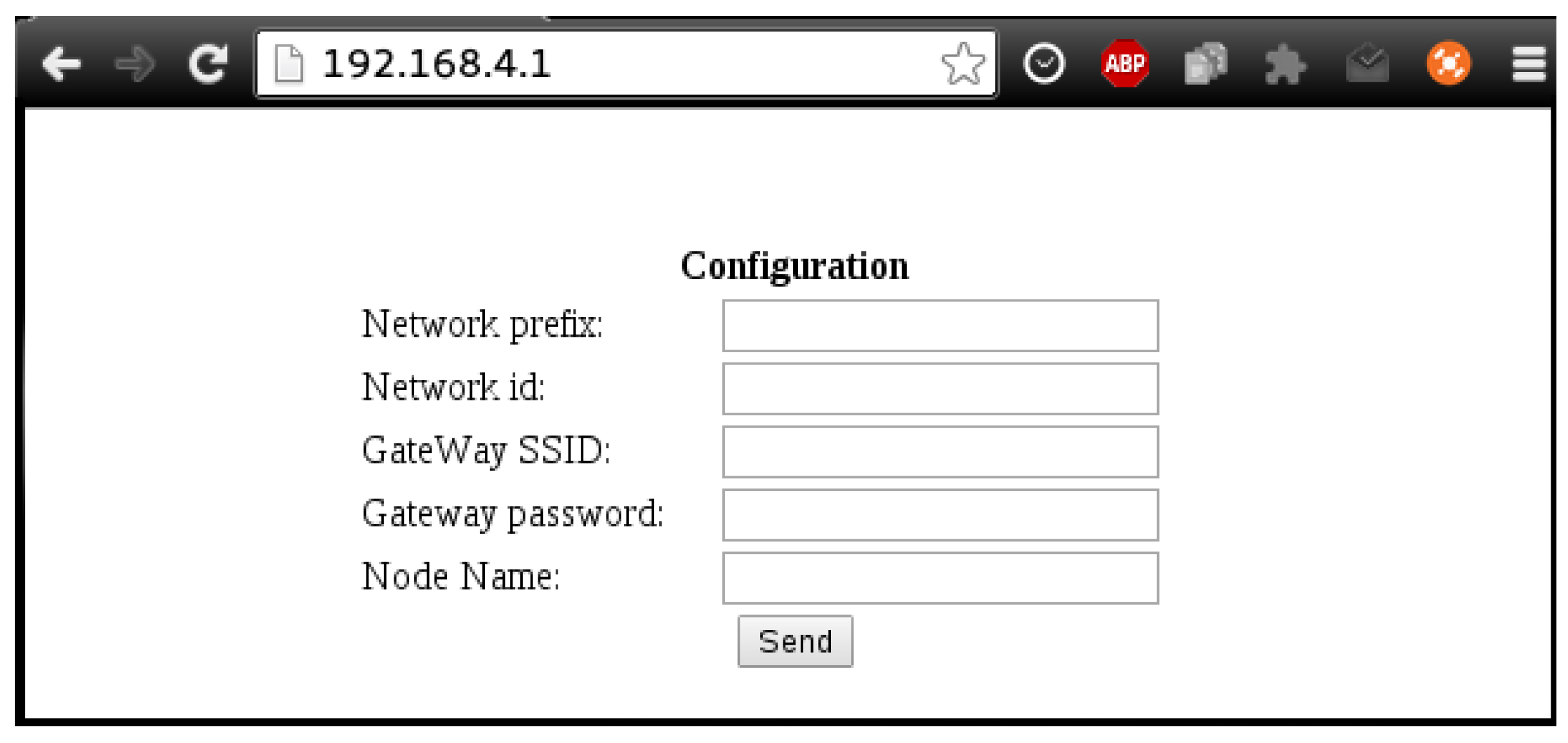
6.2. Initial Network Configuration

Setting up the system proposed is straightforward if there is an already existent Wi-Fi network. However, it is common to find routers that use NAT, which impedes the traffic from going directly through the router. As was detailed in Section 4.2, the solution to this problem consisted of implementing a TCP-level proxy server that accepts and stores persistent connections from the master nodes of each IoT network. Thus, by designing an ad hoc protocol above TCP, real-time requests can be sent to the master node through the already open connection. Then, this traffic can be redirected to the corresponding node according to the parameters defined by the protocol.
Regarding the initial configuration of each IoT node, it was decided that each node offers by default a WPA2-protected Wi-Fi network with a factory-defined random password. When a user connects to the network, each node offers access to the configuration API through an HTTP server. This approach is similar to the one offered by some commercial devices [50,52].

6.3. Obtaining the Electricity Price

In order to obtain the electricity daily prices, making requests from the master node directly to the REE was initially considered API. However, after the first tests, this approach was ruled out because of its multiple problems:
  • First, prices are supposedly published by law every day at the same time. However, in practice, the publication is delayed systematically. This fact derives having to make periodic requests until the resource becomes available. This is not a problem if a single node makes the requests, but in the case of multiple networks, each master would start polling at the same time, which is not the optimal solution in terms of energy consumption and communications traffic.
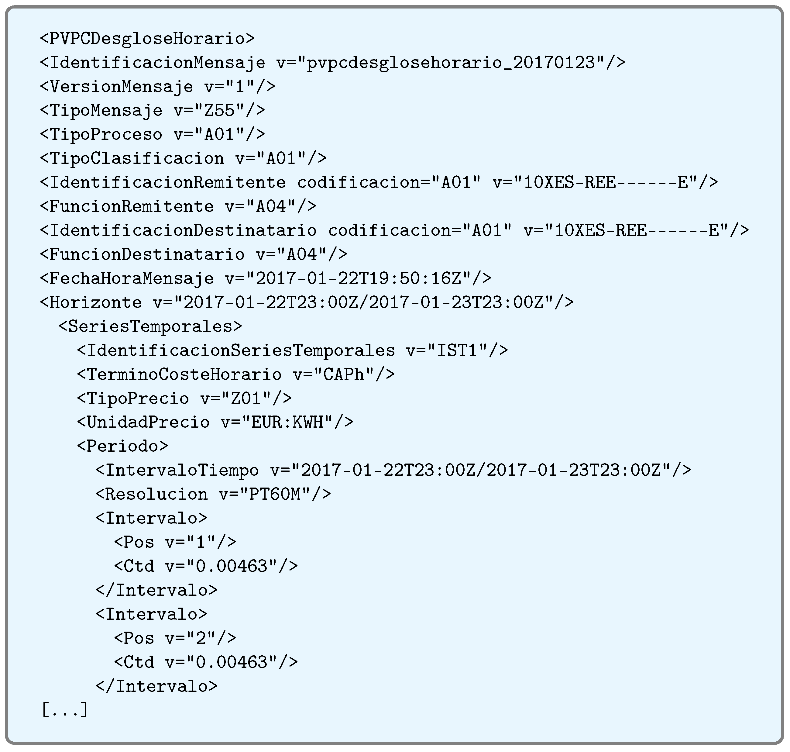
  • Second, price lists are published in a very verbose XML and with too much information that is not relevant to the system proposed. An example can be seen in Figure 12. Such a large amount of information makes the data file require more than 40 KB, an amount that may seem to be acceptable at first glance, but for an integrated system with only 96 KB of memory (in which more than 50% is used by the network protocols implemented by the manufacturer), it becomes virtually impossible to handle.
    Figure 12. Original XML verbose format.
For such reasons, it was decided to implement the intermediate server detailed in Section 4.2, which cleans the XML data and converts them into a JSON file that is compressed and much less verbose. In this way, request polling is managed by the intermediate server, and IoT nodes receive a pre-processed and much lighter response, which allows them to evaluate and store data more quickly. Thanks to this approach, the resulting file is really small. For instance, Figure 13 contains the JSON file generated from the XML shown in Figure 12: the size of the processed JSON file is only 6.1% of the original XML file size.
Figure 13. Pre-processed JSON format.
It is also worth mentioning that this intermediate server allows for quickly adapting the system in case the REE API changes the syntax of the XML file. Thus, since all of the processing is carried out by the intermediate server, it is not necessary to update the firmware of the smart sockets, just the software of the server.

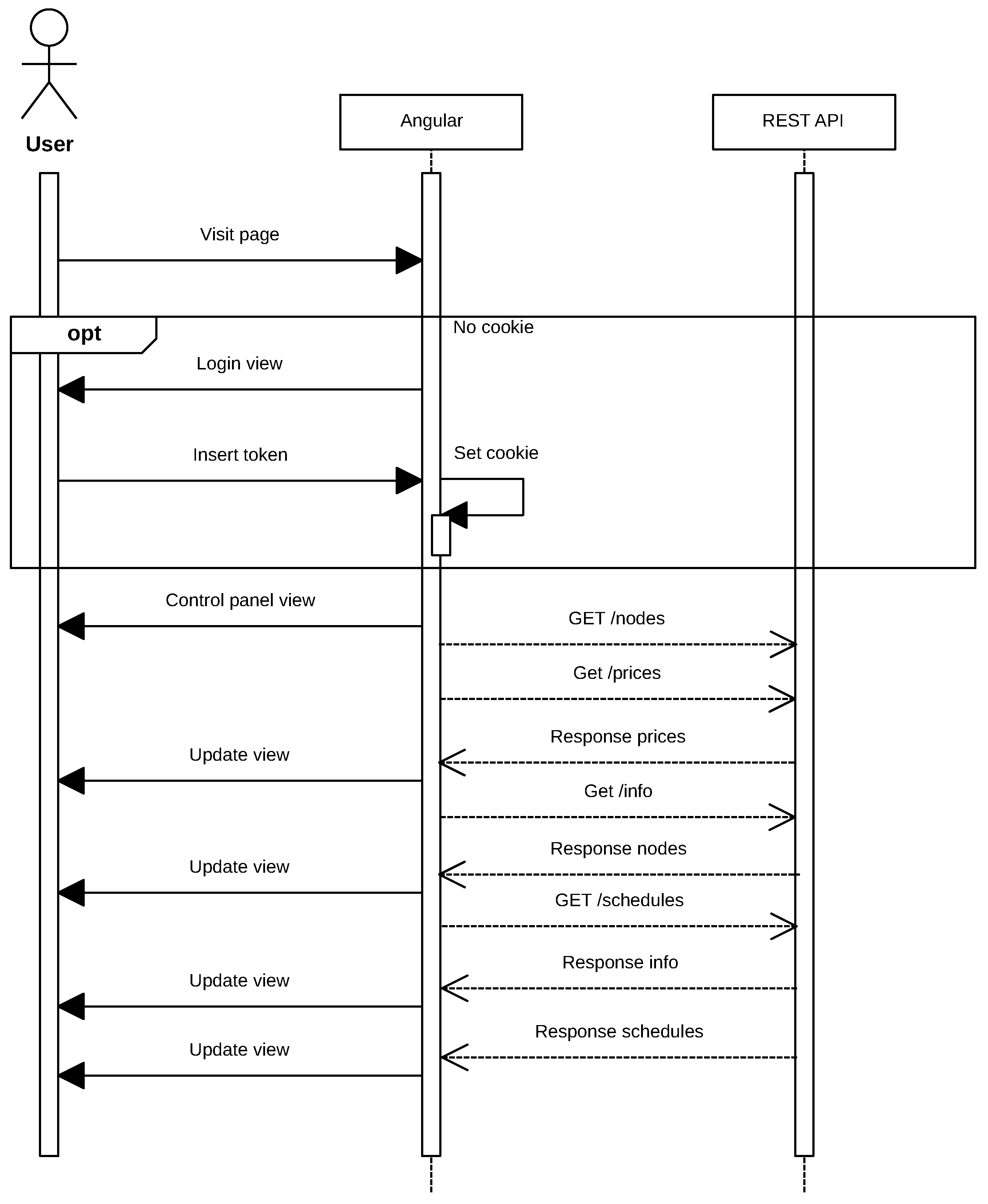
6.4. Visualization and Control Software

In order to implement the remote data visualization and control system, a web application was developed. Such a web page consisted of a single page application [77] developed using Angular2 rc5 [78]. Angular was selected due to the need for loading the data asynchronously, avoiding that the user unnecessarily waits to view the information.
The application was developed following the design recommendations for Angular2. Each module of the application was implemented in an Angular component that loads independently on demand. All components are asynchronous, and the application delegates in them all of the responsibility for obtaining the data and drawing the corresponding fragment of the interface autonomously. The interface has two modes (with and without logging in), which are managed by the presence of a session cookie. If the session has not been previously started, the login form is loaded. In such a form, the user must enter the token of the IoT network with which he or she wants to establish the communication. When the user enters the authentication token, a cookie is saved in the user’s browser, and the page is dynamically changed to show the components of the control panel (in Figure 14).
Figure 14. Main control panel.
It should be noted that a task queue had to be established in the main control panel to limit the number of web components that can send requests simultaneously. It must not be forgotten that the system manages resource-constrained IoT devices, which would be saturated if the system sends too many requests in parallel.
In Figure 15, the flow of the application can be observed when a user visits the page. The requests exchanged between the Angular application and the REST API are performed asynchronously, but, as was previously indicated, requests are limited to avoid saturating the IoT devices. It must be noted that, although in the diagram shown in Figure 15 it is not specified for the sake of clarity, the REST API makes requests to the smart plugs linked to the token introduced by the user through its own communications protocol, as was previously described in Section 4.3.
Figure 15. Web application sequence diagram.

7. Experiments

7.1. Initial Software Setup

Before performing any experiment, it is necessary to deploy the IoT network infrastructure. For such a purpose, the first step consists of deploying all of the services developed for communicating with the different subsystems.
The smart socket system presented in this paper is open-source, and all of the code can be found in [79]. This public repository can be cloned in order to deploy all services locally. After downloading the source files, the deployment is really straightforward and only requires two steps: first, a Docker [80] image has to be built by using the command docker build, and second, the Docker container has to be started with the command docker run.

7.2. Initial Configuration of the Nodes

Every new node to be added to system has to be configured to connect to a Wi-Fi access point. If the node detects that there are no other nodes in the network, it takes the role of master, connects to the access point and opens a persistent connection to the proxy server.
When the node’s power supply is first connected, it creates a Wi-Fi network with a random password that would be assigned by the manufacturer. Then, a user can connect to the Wi-Fi network created by the IoT master node and access the default IP of the embedded HTTP server (192.168.4.1). The server shows a form where the user has to indicate the network configuration data (in Figure 16), which include the name of the Wi-Fi network to be connected to (i.e., the network with Internet access) and its password. Moreover, several default parameters can be customized, like the node’s name, the network id and the network prefix. In the case of the network id, it is used as a simple authentication token within the control panel, while the network prefix determines whether two nodes belong to the same network.
Figure 16. Initial configuration form of a smart socket.

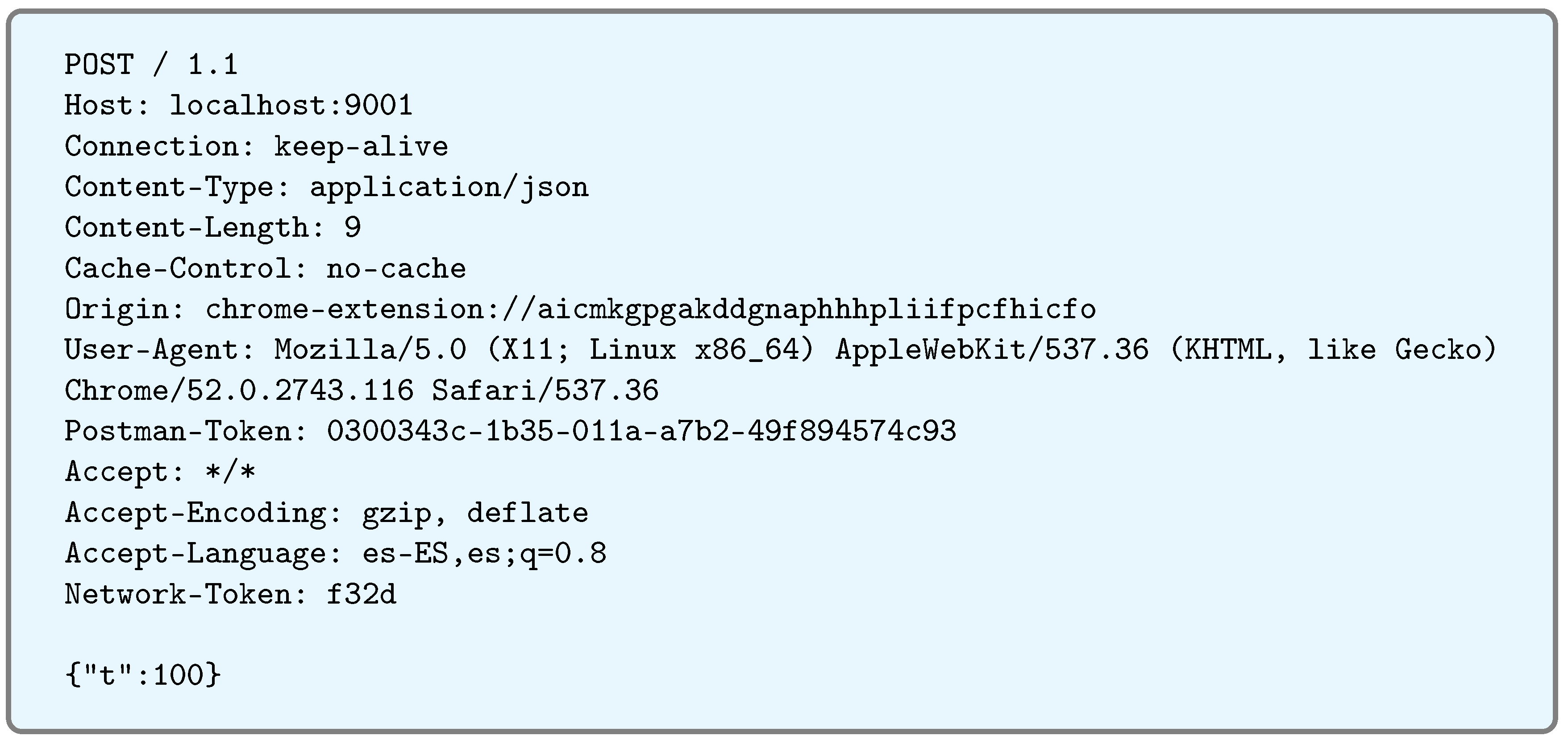
7.3. Accessing the Nodes through the REST API

Figure 17 shows an example of the REST API request that asks for information about the state of the network through PostMan. In such a request, the token of the IoT network whose data are being requested must be included (in the example shown in Figure 17 the token is “123”). The answer to the request is {“s”:0, “t”:0, “l”:0}:
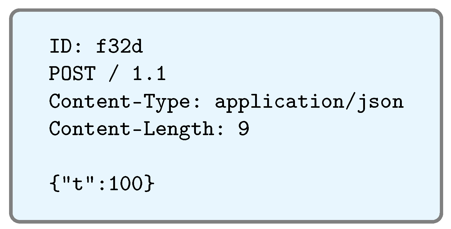
  • “s” stands for the state of the module, and it can be either 0 (off) or 1 (on).
  • “t” represents the working mode. If it is equal to 0, the socket is working in intelligent mode, while 1 is for real-time (i.e., manual) mode.
  • “l” represents the time when the last scheduling cycle took place. In the previous example, it is equal to 0, which means that it has never been a previous scheduling cycle.
Figure 17. IoT network state request sent through PostMan.

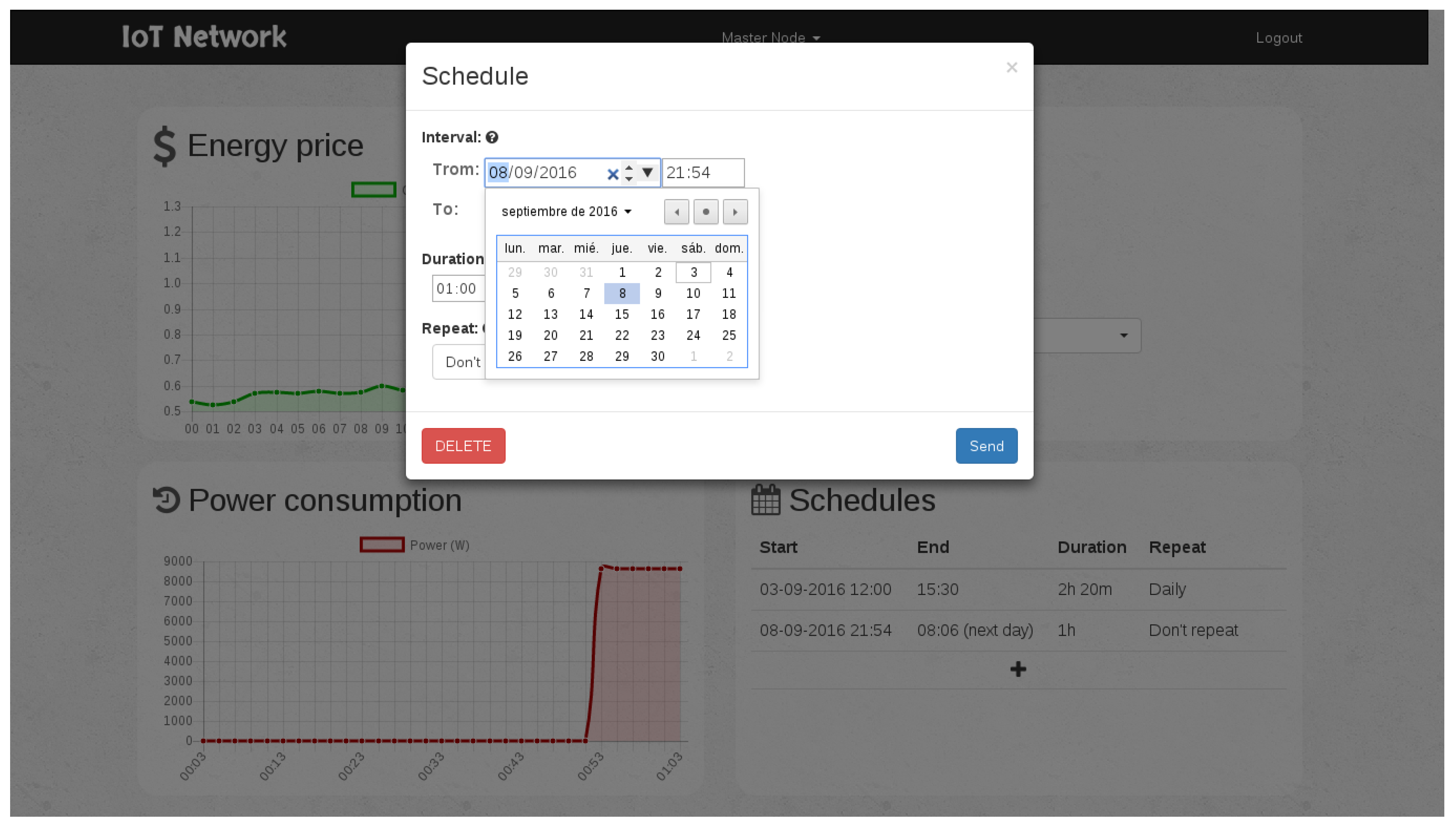
7.4. Testing the Scheduler

As an example, the scheduling module could be tested by adding a one-hour operation interval scheduled to begin within one minute. Figure 18 shows the menu where the scheduling is programmed. Thus, the scheduler is forced to switch on the power outlet after a minute, and then, it can be checked visually that it worked, for instance through a light connected to the power outlet. Note that, for this test, the scheduler had to be in manual mode in order to ignore the energy costs received. More complex schedules can be configured, as can be observed in Figure 19.
Figure 18. Example of scheduling for a one-hour operation interval.
Figure 19. Menu for scheduling the operation intervals.

7.5. Communications Range

Indoor wireless communications are exposed to several problems because radio signals are reflected, refracted, absorbed and, therefore, attenuated by obstacles. In order to test the smart socket network infrastructure created in an indoor environment, it was setup, and several measures of the signal RSSI (Received Signal Strength Indicator) were taken from different locations during the regular operation of the modules. Moreover, five measurements were averaged for each spot to counteract signal fluctuations.
It was determined that the modules transmitted with a typical power of 18.5 dBm and that the intensity of the signal measured with line-of-sight at 3 m was −50 dBm. Such signal level decreased to −62 dBm when the socket was placed behind a brick wall. If the socket was located 6 m behind two brick walls, the intensity was reduced to −71 dBm. Therefore, taking into account that the ESP8266 usually requires a minimum of −80 dBm to guarantee communications, it can be concluded that, in spite of its small size, the range offered by the device is enough for a home automation environment.

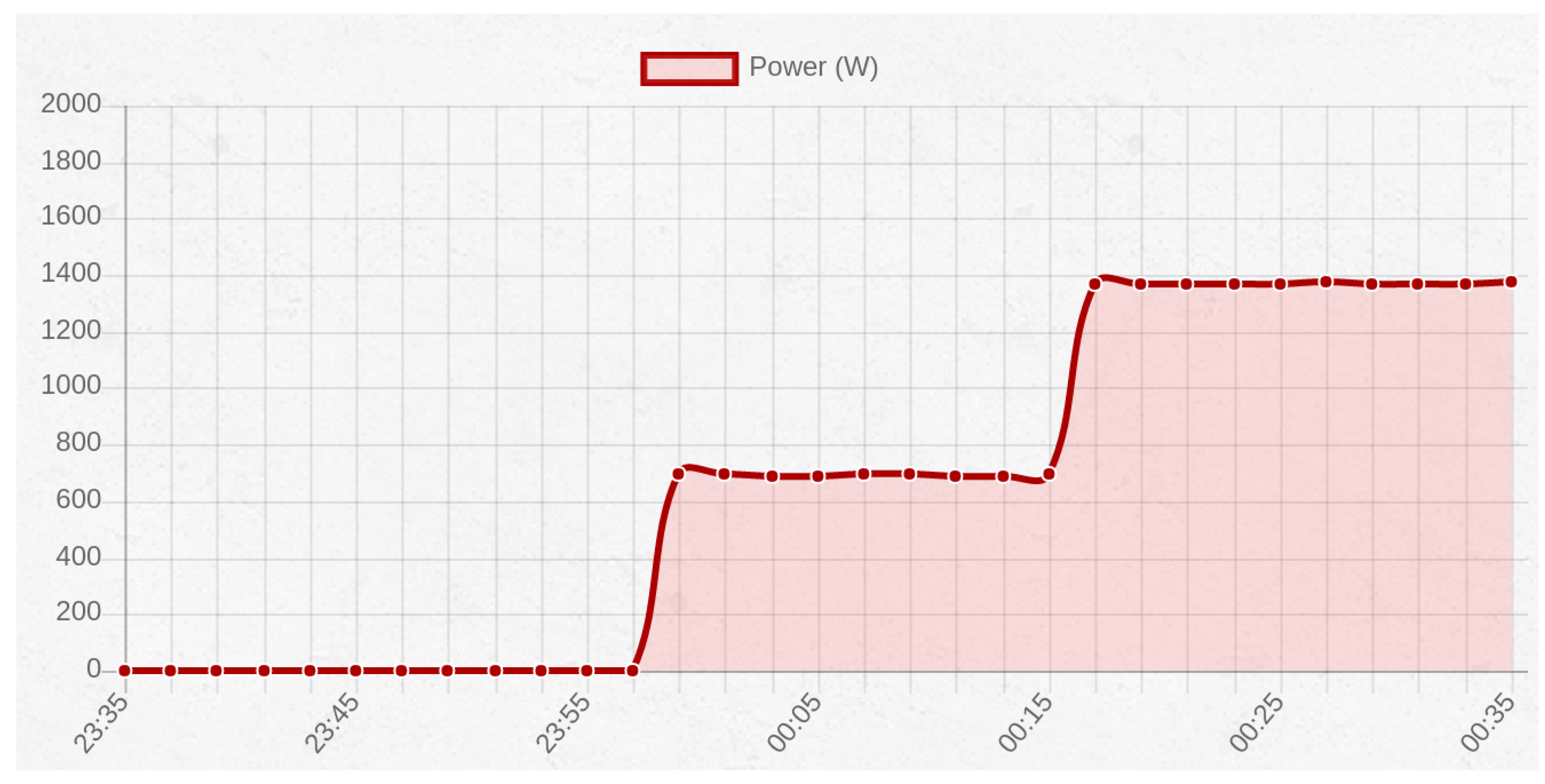
7.6. Current Monitoring

In order to test the current monitor system in a real situation, the energy consumption of an electric heater with two power levels was measured. The first power level was rated at 700 W by the manufacturer, while the second one was at 1400 W.
Figure 20 shows the real-time graph of the power consumption. First, the heater is switched on in the first level, and then, after fifteen minutes, it can be seen how the curve rises to 1400 W when the second heat level was selected. Therefore, it was concluded that the current intensity data collected are accurate both in value and timing.
Figure 20. Graph representing the power consumption of an electric heater with two heat levels.

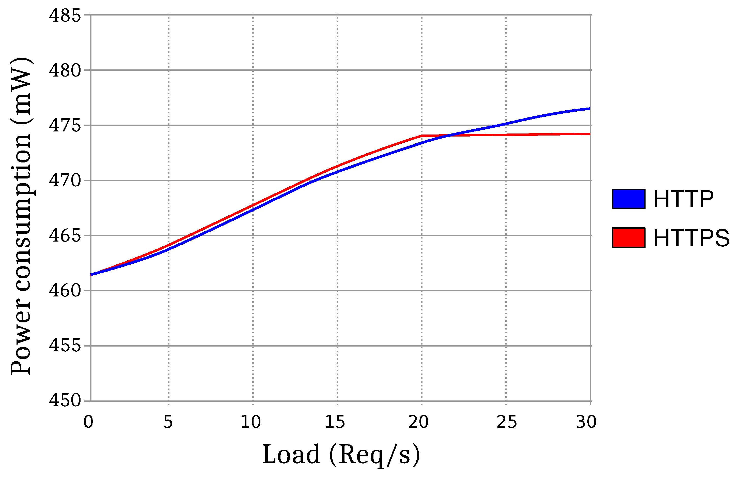
7.7. Socket Performance with and without HTTPS

In order to analyze the performance and power consumption of the socket, several load tests were carried out for evaluating HTTP and HTTPS in real situations. All tests were performed with the device connected to a Wi-Fi in the IEEE 802.11g network mode with an output power of 15 dBm. The manufacturer rates the typical power consumption for this type of connection at 462 mW.
The tests performed applied different transaction load levels to a smart socket. Thus, the device first received a low load, which consisted of two requests per second. An average power of 463.65 mW was measured, both for HTTP and HTTPS, which is really close to the data indicated by the manufacturer.
In the second test, the load was increased to 21 requests per second. The average power rose to 474.87 mW. This was the maximum power that could be measured using HTTPS, because increasing the load further causes timeouts due to the overload of the device. However, when using HTTP, since less computation is required, the load could be increased to a maximum of 61.3 requests per second, and a power of 479.82 mW was reached. As a summary, Figure 21 shows the evolution of the power consumption when increasing the number of HTTP/HTTPS requests per second.
Figure 21. Graph comparing the power consumption of the device using HTTP and HTTPS.
Regarding the performance in terms of processing delay, the differences between HTTP and HTTPS protocols were pronounced: in every test, HTTPS processing time was almost three-times slower than for plain HTTP due to the overhead of the key exchange and the computational cost associated with encryption.

7.8. Estimated Savings

This section shows an example that illustrates the cost savings that can be obtained thanks to the system proposed. It must be noted that, for the sake of clarity and simplicity, this example does not take into account time restrictions or a preferred order on the operation of the appliances (e.g., a dryer would be operated after the washing machine). Note also that the comparison excludes lighting and appliances like the oven, ceramic cook top or a TV because they are used on demand and cannot be deferred without disturbing the user preferences. Moreover, home appliances like refrigerators or freezers are not evaluated, since they have to be connected all day long. In addition, it has to be emphasized that the appliances selected are just examples, and their scheduling and use depend highly on the user preferences, his/her personal schedule and the place where the user lives (i.e., it may not be polite to switch on a noisy machine in the early morning in certain buildings).
Thus, Table 2 shows the potential savings that could be obtained by four different appliances when they are operated during the optimal cost intervals selected by the smart socket system. Specifically, the costs indicated refer to 31 January 2017 when using the default PVPC tariff. In such a scenario, the minimum FEU values were 0.12398 €/kWh (from 4:00–5:00) and 0.12596 €/kWh (from 3:00–4:00), whilst the maximum values were 0.16383 €/kWh (from 19:00–20:00) and 0.15999 €/kWh (from 18:00–19:00). These numbers indicate that a customer that operates a device at 4 a.m. saves 24.33% of the cost respect to one that switches on the same device at 7 p.m. Savings are more compelling when it is assumed that the energy consumption indicated is performed on a daily basis during a year: for the most energy-demanding appliances, savings of up to €67.41 can be achieved. The overall savings for these four appliances would reach €108.14 for a year of use.
Table 2. Savings obtained for different appliances.

7.9. Comparison to Other Energy Management Systems

The cost savings obtained in the previous section are in the same order of magnitude as the most relevant solutions found in the literature, which are compared in Table 3. It can be observed that some systems are developed specifically for optimizing the use of a specific appliance (or a set of appliances), but others, like the system proposed in this article, are aimed at providing a whole energy efficiency solution for smart homes. The features of the systems compared differ greatly, but most of them share similar objectives with the solution proposed: to increase energy efficiency and to incorporate user preferences. However, we have found no system that includes all of the functionality described in Section 6.1.
Table 3. Main characteristics of the most relevant energy management systems.
Regarding the architecture of the systems compared, most of them are HEMS that may include or not a WSN that collects data from different sensors, as does the system presented in this paper. The way energy prices are obtained is the main difference between the system proposed and the others analyzed: our system always make use of real prices obtained from a public operator, while other solutions try to predict price values or they just limit the consumption to off-peak consumption periods. Finally, in terms of cost savings, it is difficult to carry out a fair comparison, since they differ in many of the aspects previously mentioned: the technologies selected, the scheduling techniques, the systems modeled, the way energy prices are calculated and even in the possibility of using multiple energy sources.

8. Conclusions

The Internet of Energy (IoE) represents a novel paradigm of intelligent infrastructures where electrical power systems would work cooperatively with smart devices. The implementation of IoE systems involves the use of multiple software and hardware components like embedded systems, power electronics, integrated circuits, sensors, processing units or storage technologies. Such components are an essential part of the infrastructure of companies dedicated to the generation and distribution of energy and the one required by the final consumer. This article focused on the latter and presented a home automation system able to process the information about pricing and the user preferences to optimize home energy consumption. The system collects daily the data on pricing published by Red Eléctrica de España (Spanish Electrical Grid) and analyzes them to determine the operation time intervals with the lowest prices. To this end, an auto-configurable easy-to-deploy system based on a series of intelligent power outlets connected to each other through a shared Wi-Fi network was developed. Such an open-source smart socket system is able to measure the current of the appliances connected to it and send the data collected to a central control device that generates statistics and performs certain scheduled actions.
This article made three main contributions aimed at fostering IoT technologies for the IoE. First, it presents a hardware prototype and a software development able to test scheduling strategies by using actual price values from a public electricity operator. Second, the paper presented a thorough description of the design of the open-source system proposed, including its communications architecture, the protocols implemented, the main sensing and actuation components of the system and the most relevant pieces of the software developed. Third, the system proposed the features of self-organized mesh networking and auto-configuration characteristics that have not been found in the literature for any Wi-Fi smart plug.
To evaluate the performance of the smart socket system, different experiments were performed. The initial setup and configuration tests demonstrated that the open-source system is really easy to configure and deploy. The access for third-party developers was also tested, and it was shown that it is straightforward to use the REST API. Other experiments confirmed that the smart socket scheduling system and current monitoring features work fine and that the communications range is enough for home automation. The performance of the system when using plain HTTP and HTTPS was also compared: the results showed that, although in terms of average energy consumption there are no significant differences, the processing time required by HTTPS is roughly three-times greater than the one needed by HTTP, which denotes the need for more efficient and lighter ciphering suites for IoT devices. Moreover, an example was described that illustrates the cost savings achievable with the system proposed. In the scenario proposed for the experiments, an energy-demanding appliance can save up to €67.41 per year. Finally, the features of the system were compared with the most relevant energy management systems, concluding that the system offered similar energy savings, but more features than most of the systems analyzed.

Acknowledgments

This work has been funded by the Xunta de Galicia (ED431C 2016-045, ED341D R2016/012, ED431G/01), the Agencia Estatal de Investigación of Spain (TEC2013-47141-C4-1-R, TEC2015-69648-REDC, TEC2016-75067-C4-1-R) and ERDF funds of the EU (AEI/FEDER, UE).

Author Contributions

Óscar Blanco-Novoa, Tiago M. Fernández-Caramés and Paula Fraga-Lamas contributed to the overall study design, data collection and analysis and the writing of the manuscript. Luis Castedo contributed to the overall writing of the manuscript. All of the authors approved the final version of the manuscript.

Conflicts of Interest

The authors declare no conflict of interest. The founding sponsors had no role in the design of the study; in the collection, analyses or interpretation of data; in the writing of the manuscript; nor in the decision to publish the results.

Abbreviations

The following abbreviations are used in this manuscript:
APIApplication Programming Interface
BLEBluetooth Low Energy
CPSCyber-Physical Systems
DRDemand Response
EpEnergía consumida en el período tarifario p
FPUTérmino de Facturación de Potencia Unitaria
HEMSHome Energy Management System
IoEInternet of Energy
IoTInternet of Things
MCFMargen de Comercialización Fijo
NTPNetwork Time Protocol
PLCPower Line Communication
PVPCVolunteer Price for the Small Consumer
REERed Eléctrica de España
RESTRepresentational State Transfer
RFRadio Frequency
RFIDRadio Frequency IDentification
RTCReal Time Clock
SoCSystem-on-Chip
TPUTérmino de Potencia Unitario
UPSUninterruptible Power System
WSNWireless Sensor Network

References

  1. 2030 Energy Strategy, European Commission. Available online: https://ec.europa.eu/energy/en/topics/energy-strategy/2030-energy-strategy (accessed on 25 January 2017).
  2. Intended Nationally Determined Contributions (INDCS) to the Paris Agreement (C2ES, Center for Climate and Energy Solutions). Available online: https://www.c2es.org/international/2015-agreement/indcs (accessed on 25 January 2017).
  3. Fernández-Caramés, T.M.; Fraga-Lamas, P.; Suárez-Albela, M.; Castedo, L. Reverse Engineering and Security Evaluation of Commercial Tags for RFID-Based IoT Applications. Sensors 2017, 17, 28. [Google Scholar] [CrossRef] [PubMed]
  4. Fraga-Lamas, P.; Noceda-Davila, D.; Fernández-Caramés, T.M.; Díaz-Bouza, M.A.; Vilar-Montesinos, M. Smart Pipe System for a Shipyard 4.0. Sensors 2016, 16, 2186. [Google Scholar] [CrossRef] [PubMed]
  5. Bui, N.; Castellani, A.P.; Casari, P.; Zorzi, M. The internet of energy: A web-enabled smart grid system. IEEE Netw. 2012, 26, 39–45. [Google Scholar] [CrossRef]
  6. Pérez-Expósito, J.P.; Fernández-Caramés, T.M.; Fraga-Lamas, P.; Castedo, L. VineSens: An Eco-Smart Decision-Support Viticulture System. Sensors 2017, 17, 465. [Google Scholar] [CrossRef] [PubMed]
  7. Suárez-Albela, M.; Fraga-Lamas, P.; Fernández-Caramés, T.M.; Dapena, A.; González-López, M. Home Automation System Based on Intelligent Transducer Enablers. Sensors 2016, 16, 1595. [Google Scholar] [CrossRef] [PubMed]
  8. Fraga-Lamas, P.; Fernández-Caramés, T.M.; Suárez-Albela, M.; Castedo, L.; González-López, M. A Review on Internet of Things for Defense and Public Safety. Sensors 2016, 16, 1644. [Google Scholar] [CrossRef] [PubMed]
  9. Fraga-Lamas, P.; Castedo-Ribas, L.; Morales-Méndez, A.; Camas-Albar, J.M. Evolving military broadband wireless communication systems: WiMAX, LTE and WLAN. In Proceedings of the International Conference on Military Communications and Information Systems (ICMCIS), Brussels, Belgium, 23–24 May 2016; pp. 1–8.
  10. Real Decreto 216/2014 of March 28th, Boletín Oficial del Estado, Number 77, pp. 27397–27428, BOE-A-2014-3376, Ministerio de Industria, Energía y Turismo. Available online: https://www.boe.es/diario_boe/txt.php?id=BOE-A-2014-3376 (accessed on 25 January 2017).
  11. Precio Voluntario Para el Pequeño Consumidor (PVPC), Red Eléctrica de España. Available online: http://www.ree.es/es/actividades/operacion-del-sistema-electrico/precio-voluntario-pequeno-consumidor-pvpc (accessed on 25 January 2017).
  12. Lien, C.H.; Bai, Y.W.; Lin, M.B. Remote-Controllable Power Outlet System for Home Power Management. IEEE Trans. Consum. Electron. 2007, 53, 1634. [Google Scholar] [CrossRef]
  13. Lien, C.H.; Chen, H.C.; Bai, Y.W.; Lin, M.B. Power Monitoring and Control for Electric Home Appliances Based on Power Line Communication. In Proceedings of the 2008 IEEE Instrumentation and Measurement Technology Conference, Vancouver, BC, Canada, 12–15 May 2008; pp. 2179–2184.
  14. Lien, C.H.; Lin, M.B.; Bai, Y.W. Design and implementation of a remotely controllable UPS outlet system. In Proceedings of the 2008 IEEE International Symposium on Consumer Electronics, Vilamoura, Portugal, 14–16 April 2008; pp. 1–4.
  15. Lien, C.H.; Bai, Y.W.; Chen, H.C.; Hung, C.H. Home appliance energy monitoring and controlling based on Power Line Communication. In Proceedings of the 2009 IEEE International Symposium on Consumer Electronics, Las Vegas, NV, USA; 2009; pp. 1–2. [Google Scholar]
  16. Lee, M.; Uhm, Y.; Kim, Y.; Kim, G.; Park, S. Intelligent power management device with middleware based living pattern learning for power reduction. IEEE Trans. Consum. Electron. 2009, 55, 2081–2089. [Google Scholar] [CrossRef]
  17. Horvat, G.; Vinko, D.; Žagar, D. Household power outlet overload protection and monitoring using cost effective embedded solution. In Proceedings of the 2nd Mediterranean Conference on Embedded Computing (MECO), Budva, Montenegro, 15–20 June 2013; pp. 242–246.
  18. Garcia, M.R.G.; Chan, H.R.B.; Comendador, B.E.V.; Cornell, G.B.; Celestial, C.D.; Mercolesia, A.E.P. Smart Home Electricity Management System Using Cloud Computing (SHEMS). J. Adv. Comput. Netw. 2013, 1, 44–48. [Google Scholar] [CrossRef]
  19. Shajahan, A.H.; Anand, A. Data acquisition and control using Arduino-Android platform: Smart plug. In Proceedings of the 2013 International Conference on Energy Efficient Technologies for Sustainability, Nagercoil, India, 10–12 April 2013; pp. 241–244.
  20. Horvat, I.; Lukac, N.; Pavlovic, R.; Starcevic, D. Smart plug solution based on bluetooth low energy. In Proceedings of the 2015 IEEE 5th International Conference on Consumer Electronics - Berlin (ICCE-Berlin), Berlin, Germany, 6–9 September 2015; pp. 435–437.
  21. Lentine, A.L.; Ford, J.R.; Finn, J.R.; Furrer, C.T.; Bryan, J.R.; Gonzalez, S.; Spires, S.V.; Goldsmith, S.Y. An intelligent electrical outlet for autonomous load control for electric power grids with a large percentage of renewable resources. In Proceedings of the 2012 IEEE Power and Energy Society General Meeting, San Diego, CA, USA, 22–26 July 2012; pp. 1–8.
  22. Morsali, H.; Shekarabi, S.M.; Ardekani, K.; Khayami, H.; Fereidunian, A.; Ghassemian, M.; Lesani, H. Smart plugs for building energy management systems. In Proceedings of 2nd Iranian Conference on Smart Grids, Tehran, Iran, 24–25 May 2012; pp. 1–5.
  23. Bai, Y.W.; Hung, C.H. Remote power On/Off control and current measurement for home electric outlets based on a low-power embedded board and ZigBee communication. In Proceedings of the 2008 IEEE International Symposium on Consumer Electronics, Vilamoura, Portugal, 14–16 April 2008; pp. 1–4.
  24. Ahmed, M.S.; Mohamed, A.; Homod, R.Z.; Shareef, H.; Sabry, A.H.; Bin Khalid, K. Smart plug prototype for monitoring electrical appliances in Home Energy Management System. In Proceedings of the 2015 IEEE Student Conference on Research and Development (SCOReD), Kuala Lumpur, Malaysia, 13–14 December 2015; pp. 32–36.
  25. Kau, L.J.; Dai, B.L.; Chen, C.S.; Chen, S.H. A cloud network-based power management technology for smart home systems. In Proceedings of the 2012 IEEE International Conference on Systems, Man, and Cybernetics (SMC), Seoul, Korea, 14–17 October 2012; pp. 2527–2532.
  26. Han, J.; Lee, H.; Park, K.R. Remote-controllable and energy-saving room architecture based on ZigBee communication. IEEE Trans. Consum. Electron. 2009, 55, 264–268. [Google Scholar] [CrossRef]
  27. Fernández-Caramés, T.M. An Intelligent Power Outlet System for the Smart Home of the Internet of Things. Int. J. Distrib. Sens. Netw. 2015, 2015, 214805. [Google Scholar] [CrossRef] [PubMed]
  28. Choi, M.; Park, W.K.; Lee, I. Smart Office Energy-Saving Service Using Bluetooth Low Energy Beacons and Smart Plugs. In Proceedings of 2015 IEEE International Conference on Data Science and Data Intensive Systems, Sydney, Australia, 11–13 December 2015; pp. 247–251.
  29. Thongkhao, Y.; Pora, W. A low-cost Wi-Fi smart plug with on-off and Energy Metering functions. In Proceedings of 2016 13th International Conference on Electrical Engineering/Electronics, Computer, Telecommunications and Information Technology (ECTI-CON), Chiang Mai, Thailand, 28 June–1 July 2016; pp. 1–5.
  30. Xiong, G.; Chen, C.; Kishore, S.; Yener, A. Smart (in-home) power scheduling for demand response on the smart grid. In Proceedings of the 2011 IEEE PES Innovative Smart Grid Technologies (ISGT), Hilton Anaheim, CA, USA, 17–19 January 2011; pp. 1–7.
  31. Kim, T.T.; Poor, H.V. Scheduling Power Consumption With Price Uncertainty. IEEE Trans. Smart Grid 2011, 2, 519–527. [Google Scholar] [CrossRef]
  32. Ridi, A.; Gisler, C.; Hennebert, J. Automatic identification of electrical appliances using smart plugs. In Proceedings of 2013 8th International Workshop on Systems, Signal Processing and their Applications (WoSSPA), Algiers, Algeria, 12–15 May 2013; pp. 301–305.
  33. Ridi, A.; Gisler, C.; Hennebert, J. Processing smart plug signals using machine learning. In Proceedings of 2015 IEEE Wireless Communications and Networking Conference Workshops (WCNCW), New Orleans, LA, USA, 9–12 March 2015; pp. 75–80.
  34. Leonardi, A.; Ziekow, H.; Konchalenkov, D.; Rogozina, A. Detecting Smart Plug Configuration Changes in Smart Homes. In Proceedings of Smart SysTech 2014; European Conference on Smart Objects, Systems and Technologies, Dortmund, Germany, 1–2 July 2014; pp. 1–7.
  35. Santoro, P.; Calderaro, V.; Galdi, V.; Piccolo, A. Active smart socket design to perform local control of power demand in residential units. In Proceedings of 8th IET International Conference on Power Electronics, Machines and Drives (PEMD 2016), Glasgow, UK, 19–21 April 2016; pp. 1–5.
  36. Elma, O.; Selamoğullari, U.S. A home energy management algorithm with smart plug for maximized customer comfort. In Proceedings of 2015 4th International Conference on Electric Power and Energy Conversion Systems (EPECS), Sharjah, United Arab Emirates, 24–26 November 2015; pp. 1–4.
  37. Rodney Tan, H.G.; Tan, A.C.; Iriana, M.; Mok, V.H. Power socket programmable circuit breaker system. In Proceedings of the 2nd IEEE International Power and Energy Conference, Johor Bahru, Malaysia, 1–3 December 2008; pp. 574–577.
  38. Tsunoda, Y.; Tsuchiya, C.; Segawa, Y.; Sawaya, H.; Hasegawa, M.; Ishigaki, S.; Ishibashi, K. A small-size energy-harvesting electric power sensor for implementing existing electrical appliances into HEMS. IEEE Sens. J. 2016, 16, 457–463. [Google Scholar] [CrossRef]
  39. Rastegar, M.; Fotuhi-Firuzabad, M.; Zareipour, H. Home energy management incorporating operational priority of appliances. Int. J. Electr. Power Energy Syst. 2015, 74, 286–292. [Google Scholar] [CrossRef]
  40. Siebert, L.C.; Ferreira, L.R.; Yamakawa, E.K.; Custódio, E.S.; Aoki, A.R.; Fernandes, T.S.P. Centralized and decentralized approaches to demand response using smart plugs. In Proceedings of 2014 IEEE PES T&D Conference and Exposition, Chicago, IL, USA, 14–17 April 2014; pp. 1–5.
  41. Tsai, Y.S.; Chu, C.Y.; Li, M.C.; Lin, Y.H.; Chen, P. Intelligent DC power monitoring system and sensor network based on ZigBee-equipped smart sockets. In Proceedings of 2016 5th International Symposium on Next-Generation Electronics (ISNE), Hsinchu, Taiwan, 4–6 May 2016; pp. 1–4.
  42. Shie, M.C.; Lin, P.C.; Su, T.M.; Chen, P.; Hutahaean, A. Intelligent energy monitoring system based on ZigBee-equipped smart sockets. In Proceedings of 2014 International Conference on Intelligent Green Building and Smart Grid (IGBSG), Taipei, Taiwan, 23–25 April 2014; pp. 1–5.
  43. Babu, V.S.; Kumar, U.A.; Priyadharshini, R.; Premkumar, K.; Nithin, S. An intelligent controller for smart home. In Proceedings of 2016 International Conference on Advances in Computing, Communications and Informatics (ICACCI), Jaipur, India, 21–24 September 2016; pp. 2654–2657.
  44. Karfopoulos, E.; Tena, L.; Torres, A.; Salas, P.; Jorda, J.G.; Dimeas, A.; Hatziargyriou, N. A multi-agent system providing demand response services from residential consumers. Electr. Power Syst. Res. 2015, 120, 163–176. [Google Scholar] [CrossRef]
  45. Pilloni, V.; Floris, A.; Meloni, A.; Atzori, L. Smart Home Energy Management Including Renewable Sources: A QoE-driven Approach. IEEE Trans. Smart Grid 2016. [Google Scholar] [CrossRef]
  46. Du, P.; Lu, N. Appliance Commitment for Household Load Scheduling. IEEE Trans. Smart Grid 2011, 2, 411–419. [Google Scholar] [CrossRef]
  47. Jo, H.C.; Kim, S.; Joo, S.K. Smart heating and air conditioning scheduling method incorporating customer convenience for home energy management system. IEEE Trans. Consum. Electron. 2013, 59, 316–322. [Google Scholar] [CrossRef]
  48. Zhang, D.; Li, S.; Sun, M.; O’Neill, Z. An Optimal and Learning-Based Demand Response and Home Energy Management System. IEEE Trans. Smart Grid 2016, 7, 1790–1801. [Google Scholar] [CrossRef]
  49. Chen, S.; Liu, T.; Gao, F.; Ji, J.; Xu, Z.; Qian, B.; Guan, X. Butler, Not Servant: A Human-Centric Smart Home Energy Management System. IEEE Commun. Mag. 2017, 55, 27–33. [Google Scholar] [CrossRef]
  50. Belkin’s WeMo Official Website. Available online: http://www.belkin.com/us/Products/home-automation/c/wemo-home-automation/ (accessed on 25 January 2017).
  51. Orvibo Official Website. Available online: http://www.orvibo.com.es/ (accessed on 25 January 2017).
  52. D-link’s Smart Plug Official Website. Available online: http://us.dlink.com/products/connected-home/wi-fi-smart-plug/ (accessed on 25 January 2017).
  53. MeterPlug on Sticknfind. Available online: https://www.sticknfind.com/MeterPlug/ (accessed on 25 January 2017).
  54. SafePlug Official Website. Available online: http://www.safeplug.com/ (accessed on 25 January 2017).
  55. Edimax Smart Plug Switch Official Website. Available online: http://www.edimax.com/edimax/merchandise/merchandisedetail/data/edimax/global/homeautomationsmartplug/sp-2101w/ (accessed on 25 January 2017).
  56. MyPlug 2 Official Website. Available online: http://www.my-plug.fr/decouvrir/myplug2 (accessed on 25 January 2017).
  57. Plugwise Official Website. Available online: https://www.plugwise.com/ (accessed on 25 January 2017).
  58. SwannOne Smart Plug Official Website. Available online: http://www.swannone.com/gb/swannone-smart-plug (accessed on 25 January 2017).
  59. Thinkeco’s MyModlet Official Website. Available online: https://mymodlet.com (accessed on 25 January 2017).
  60. Ankuoo Official Website. Available online: http://www.ankuoo.com/ (accessed on 25 January 2017).
  61. Kampianakis, E.; Kimionis, J.; Tountas, K.; Konstantopoulos, C.; Koutroulis, E.; Bletsas, A. Wireless Environmental Sensor Networking With Analog Scatter Radio and Timer Principles. IEEE Sens. J. 2014, 14, 3365–3376. [Google Scholar] [CrossRef]
  62. Barro-Torres, S.; Fernández-Caramés, T.M.; Escudero, C.J. Enabling Collaborative Musical Activities through Wireless Sensor Networks (WSN). Int. J. Distrib. Sens. Netw. 2012, 8, 1–13. [Google Scholar]
  63. Barro-Torres, S.J.; Fernández-Caramés, T.M.; Pérez-Iglesias, H.J.; Escudero, C.J. Real-Time Personal Protective Equipment Monitoring System. Comput. Commun. 2012, 36, 42–50. [Google Scholar] [CrossRef]
  64. ZigBee Alliance Webpage on ZigBee IP. Available online: http://www.zigbee.org/zigbee-for-developers/network-specifications/zigbeeip/ (accessed on 25 January 2017).
  65. IETF 6LoWPANWorking Group. RFC 4919: IPv6 over Low-Power Wireless Personal Area Networks (6LoWPANs): Overview, Assumptions, Problem Statement, and Goals; IETF: Reston, VA, USA, 2008. [Google Scholar]
  66. Red Eléctrica de España (REE). Available online: http://www.ree.es/en/ (accessed on 25 January 2017).
  67. PostMan Official Website. Available online: https://www.getpostman.com (accessed on 25 January 2017).
  68. Iniewski, K. Smart Sensors for Industrial Applications, 2nd ed.; CRC Press: Boca Raton, FL, USA, 2013. [Google Scholar]
  69. ACS712 Datasheet. Available online: http://www.allegromicro.com/~/media/Files/Datasheets/ACS712-Datasheet.ashx?la=en (accessed on 25 January 2017).
  70. Songle’s SRD Relay Datasheet. Available online: http://www.songle.com/en/pdf/20084141716341001.pdf (accessed on 25 January 2017).
  71. Espressif’s ESP8266 Overview. Available online: https://espressif.com/en/products/hardware/esp8266ex/overview (accessed on 25 January 2017).
  72. NodeMCU Official Website. Available online: http://www.nodemcu.com (accessed on 25 January 2017).
  73. WeMos D1 Mini Board Official Website. Available online: https://www.wemos.cc/product/d1-mini.html (accessed on 25 January 2017).
  74. Espressif Official Website. Available online: http://espressif.com/ (accessed on 25 January 2017).
  75. Ivan Grokhotkov’s ESP8266 Arduino Repository. Available online: https://github.com/esp8266/Arduino (accessed on 25 January 2017).
  76. Red Eléctrica de España (REE) API Website. Available online: https://api.esios.ree.es/ (accessed on 25 January 2017).
  77. Fink, G.; Flatow, I. Pro Single Page Application Development: Using Backbone.Js and ASP.Net, 1st ed.; Springer: New York, NY, USA, 2014. [Google Scholar]
  78. Angular2 Framework Official Website. Available online: https://angular.io/ (accessed on 25 January 2017).
  79. Smart Socket’s GitHub Repository for the IoT Server. Available online: https://github.com/4m1g0/IOT_server (accessed on 25 January 2017).
  80. Docker Official Website. Available online: https://www.docker.com/ (accessed on 25 January 2017).

Article Metrics

Citations

Article Access Statistics

Multiple requests from the same IP address are counted as one view.