Improved Numerical Calculation of the Single-Mode-No-Core-Single-Mode Fiber Structure Using the Fields Far from Cutoff Approximation

 ,
,  ,
,  ,
, 
Abstract
:1. Introduction
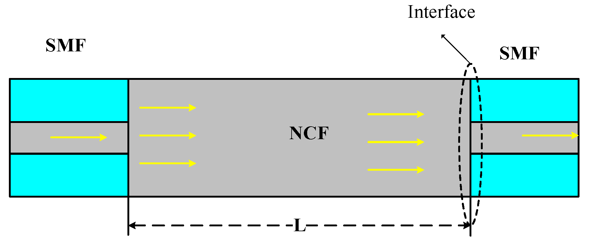
2. Theory Proposal
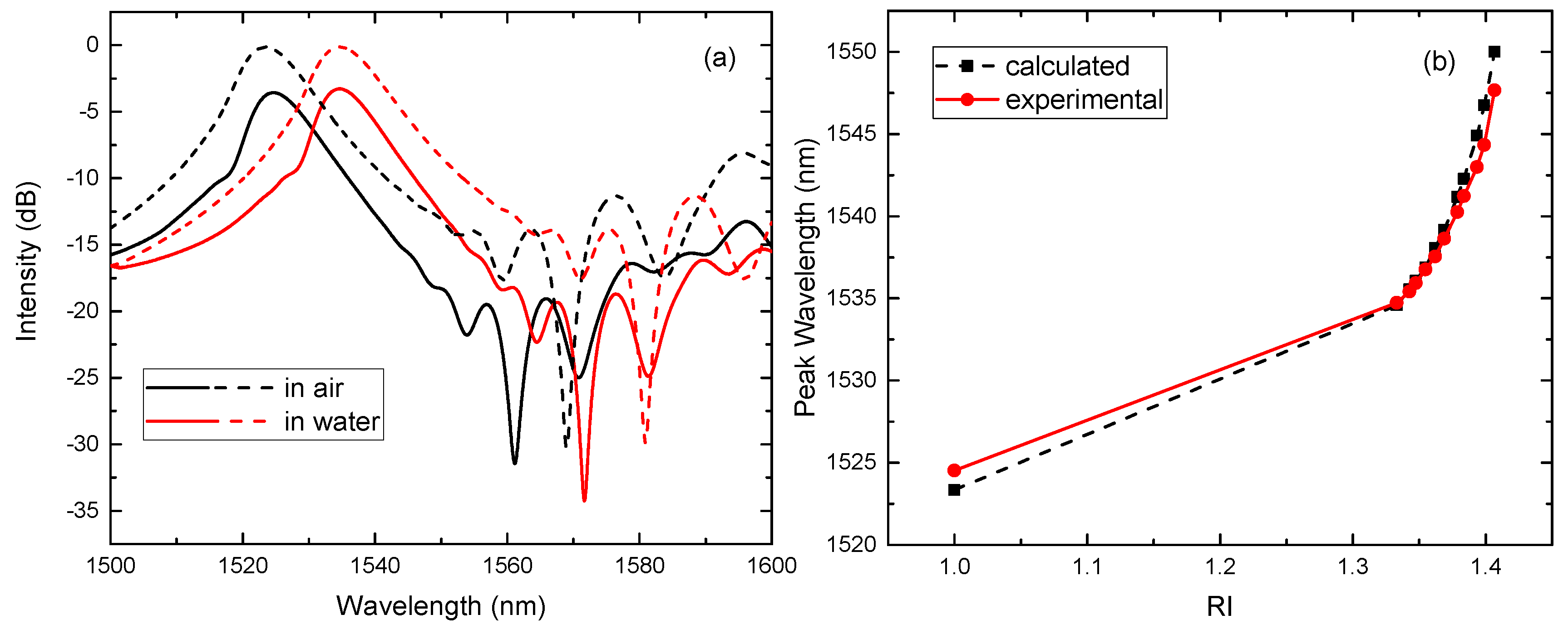
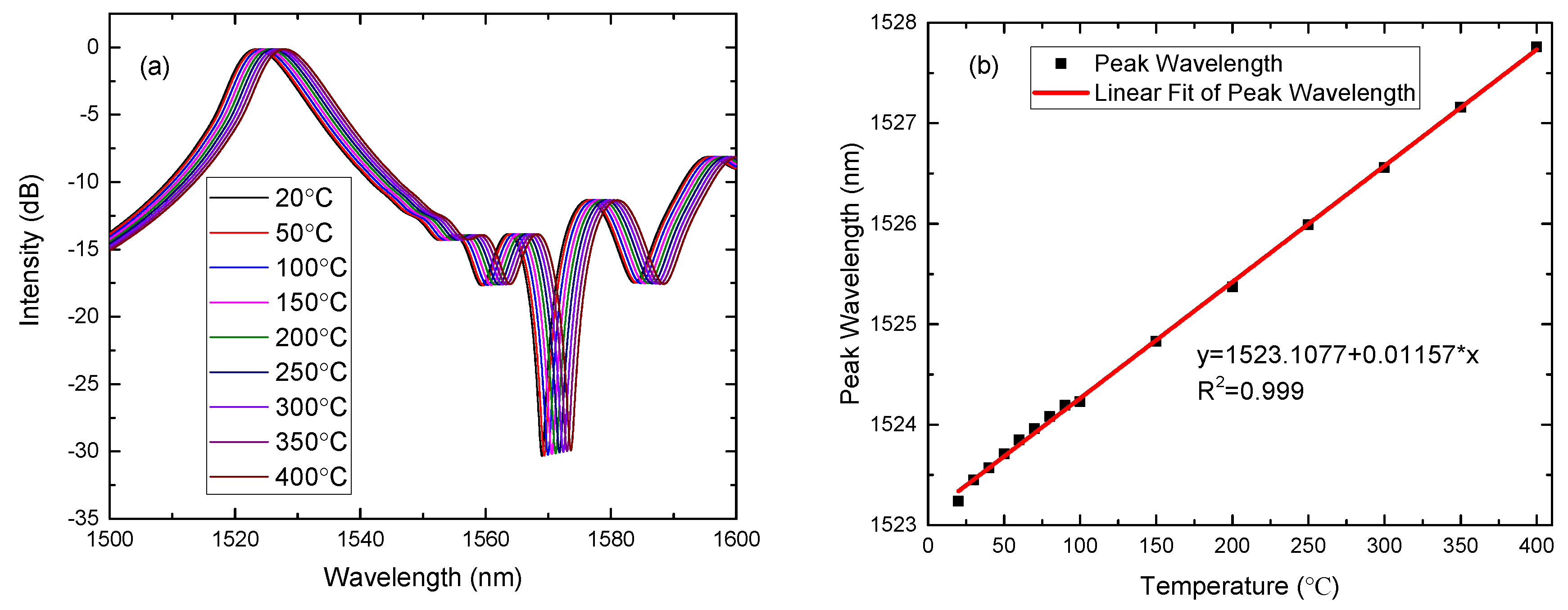
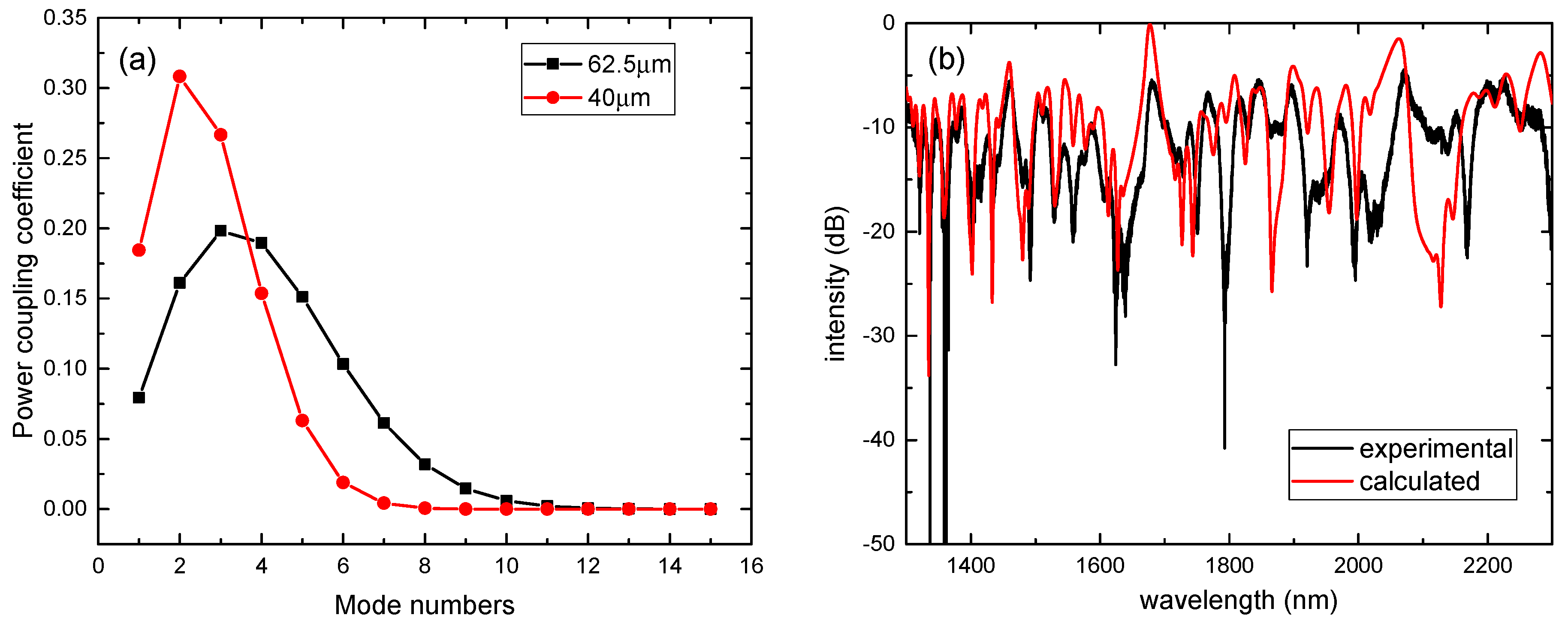
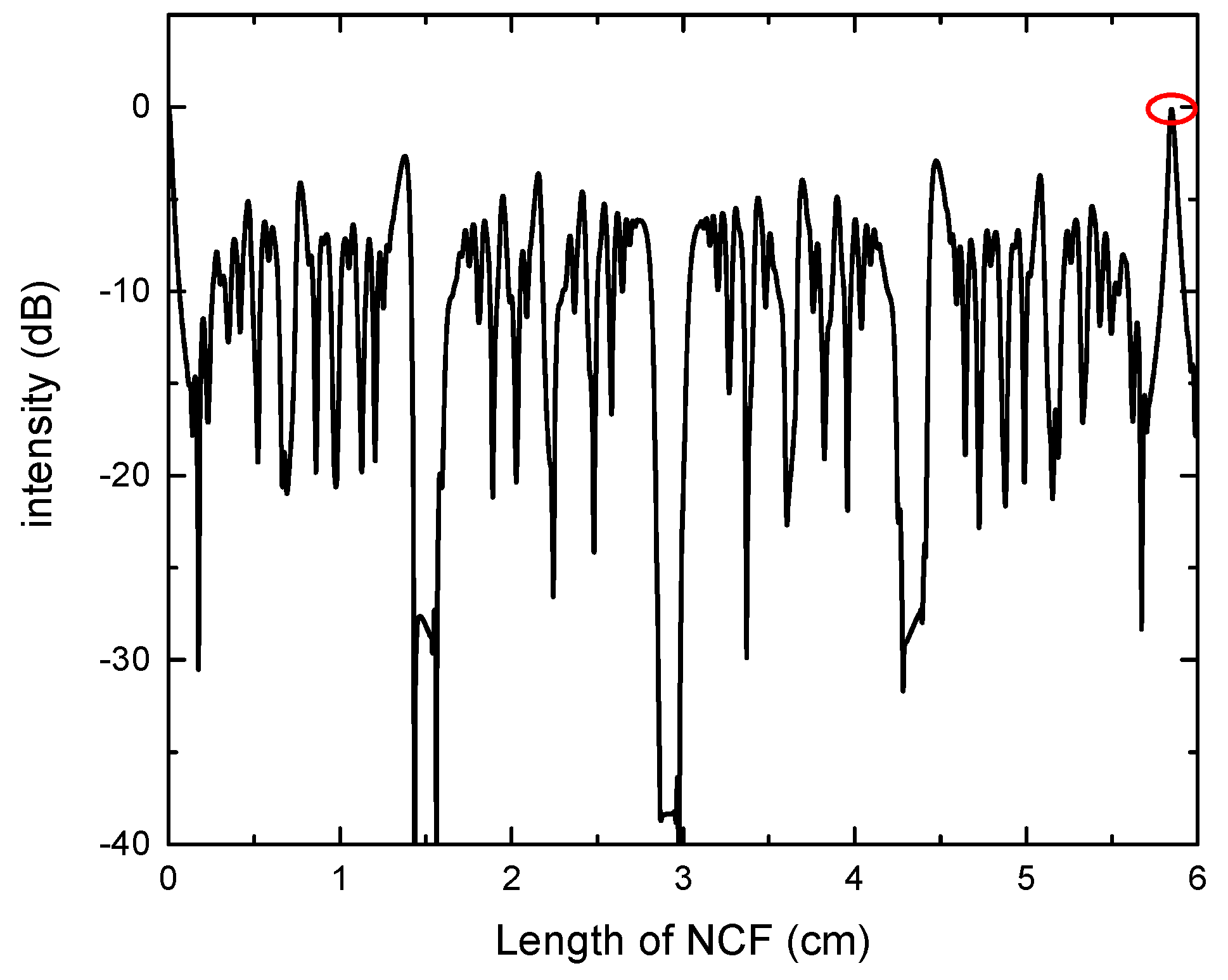
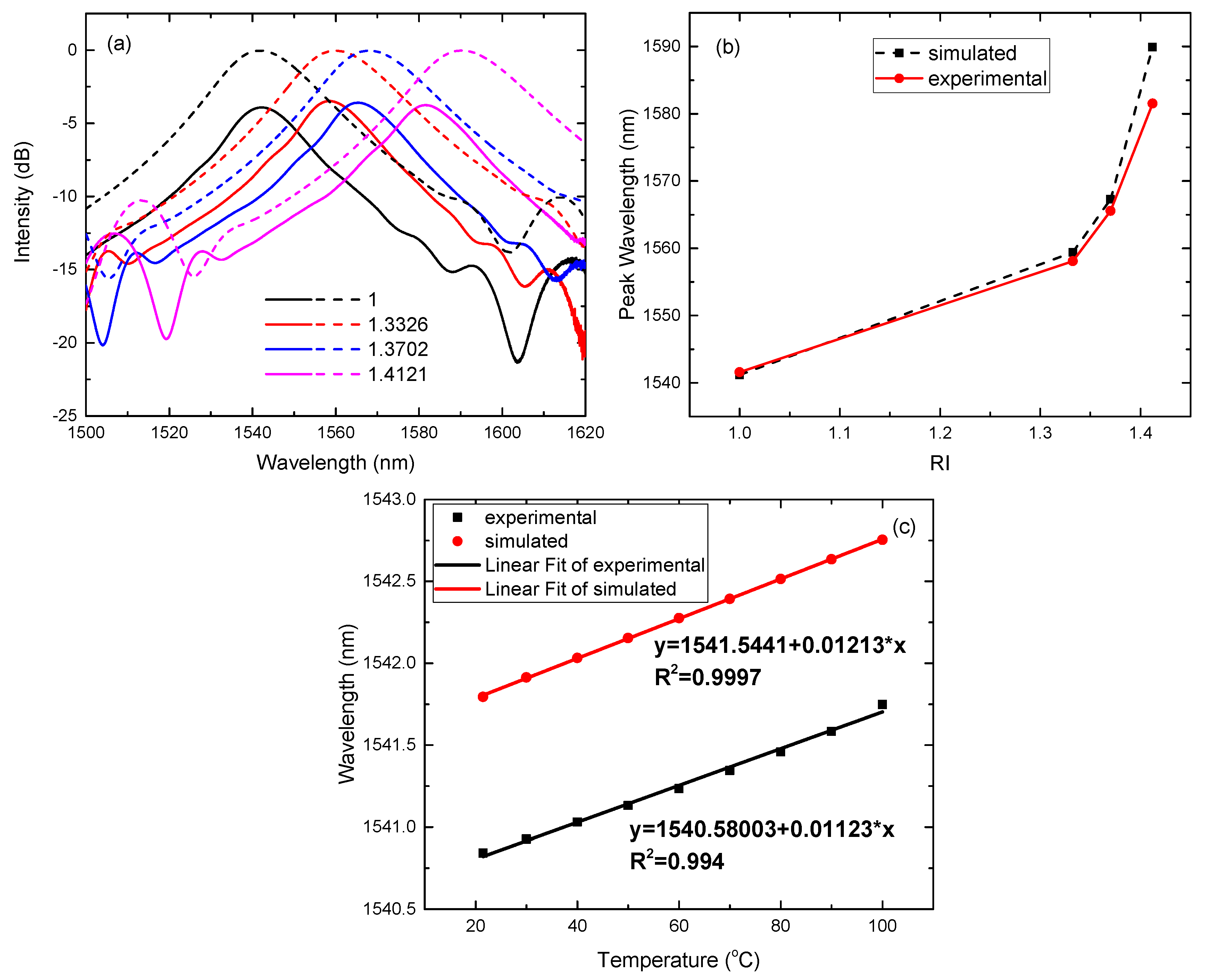
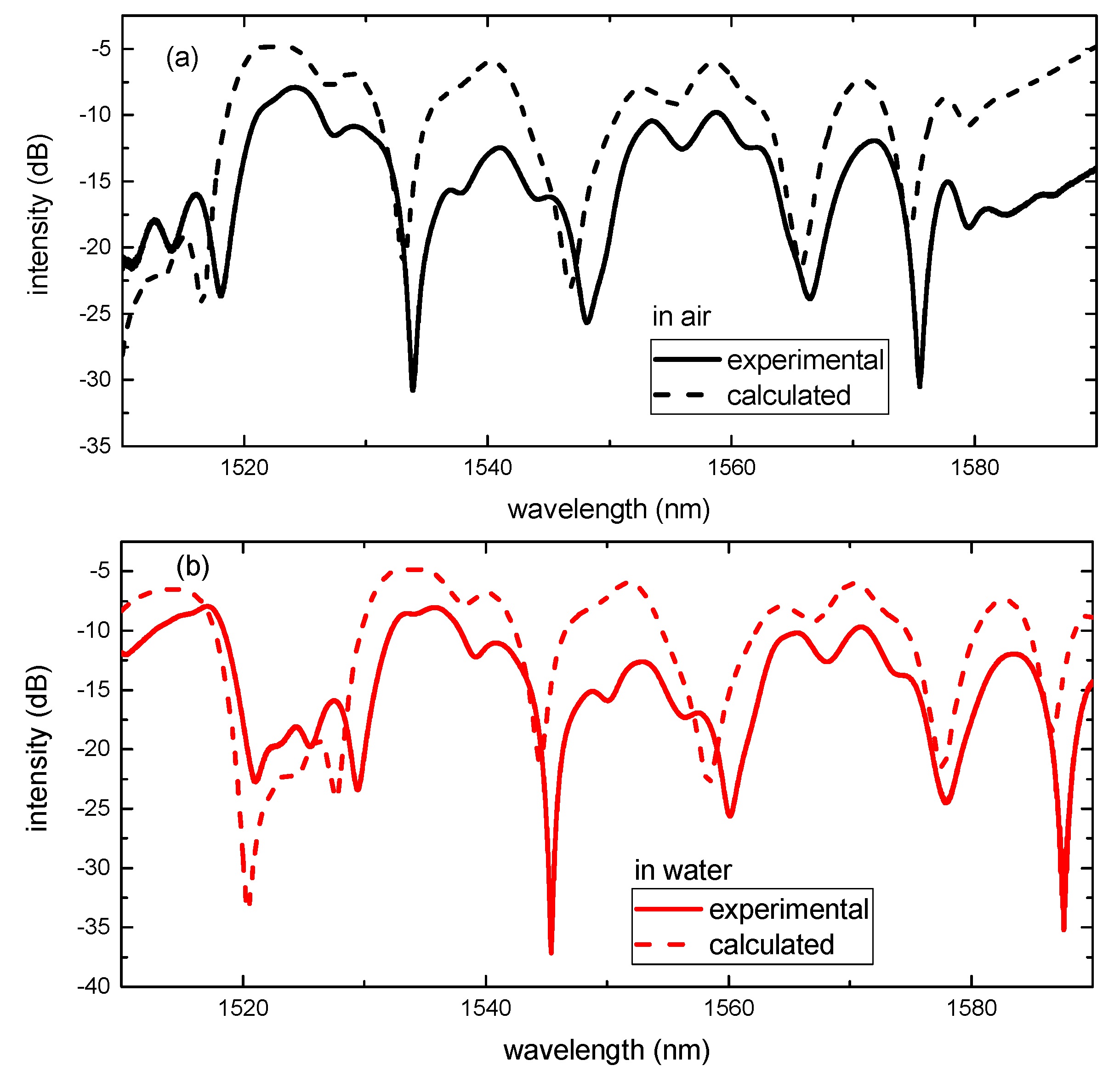
3. Simulations and Experiments
4. Conclusions
Acknowledgments
Author Contributions
Conflicts of Interest
References
- Antonio-Lopez, J.E.; Castillo-Guzman, A.; May-Arrioja, D.A.; Selvas-Aguilar, R.; LiKamWa, P. Tunable Multimode Interference Bandpass Fiber Filter. Opt. Lett. 2010, 35, 324–326. [Google Scholar] [CrossRef] [PubMed]
- Antonio-Lopez, J.E.; Sanchez-Mondragon, J.J.; LiKamWa, P.; May-Arrioja, D.A. Fiber-optic sensor for liquid level measurement. Opt. Lett. 2011, 36, 3425–3427. [Google Scholar] [CrossRef] [PubMed]
- Zhang, J.Z.; Peng, S.J. A Compact SMS Refractometer Based on HF Corrosion Scheme. In Proceedings of the Symposium on Photonics and Optoelectronics (SOPO), Chengdu, Sichuan, China, 19–21 June 2010. [Google Scholar]
- Huang, L.S.; Lin, G.R.; Fu, M.Y.; Sheng, H.J.; Sun, H.T.; Liu, W.F. A refractive-index fiber sensor by using no-core fibers. In Proceedings of the IEEE International Symposium on Next-Generation Electronics (ISNE), Kaohsiung, Taiwan, 25–26 February 2013. [Google Scholar]
- Ran, Y.L.; Xia, L.; Han, Y.; Li, W.; Rohollahnejad, J.; Wen, Y.Q.; Liu, D.M. Vibration Fiber Sensors Based on SM-NC-SM Fiber Structure. IEEE Photonics J. 2015, 7, 1–7. [Google Scholar] [CrossRef]
- Wu, Q.; Semenova, Y.; Wang, P.F.; Farrell, G. High sensitivity SMS fiber structure based refractometer— Analysis and experiment. Opt. Express 2011, 19, 7937–7944. [Google Scholar] [CrossRef] [PubMed]
- Jha, R.; Villatoro, J.; Badenes, G. Ultrastable in reflection photonic crystal fiber modal interferometer for accurate refractive index sensing. Appl. Phys. Lett. 2008, 93, 191106. [Google Scholar] [CrossRef]
- Zhu, Y.; He, Z.; Du, H. Detection of external refractive index change with high sensitivity using long-period gratings in photonic crystal fiber. Sens. Actuators B Chem. 2008, 131, 265–269. [Google Scholar] [CrossRef]
- Tan, Y.C.; Ji, W.B.; Mamidala, V.; Chow, K.K.; Tjin, S.C. Carbon-nanotube-deposited long period fiber grating for continuous refractive index sensor applications. Sens. Actuators B Chem. 2014, 196, 260–264. [Google Scholar] [CrossRef]
- Tan, Y.C.; Tou, Z.Q.; Mamidala, V.; Chow, K.K.; Chan, C.C. Continuous refractive index sensing based on carbon-nanotube-deposited photonic crystal fibers. Sens. Actuators B Chem. 2014, 202, 1097–1102. [Google Scholar] [CrossRef]
- Dash, J.N.; Jha, R. Graphene-based birefringent photonic crystal fiber sensor using surface plasmon resonance. IEEE Photonics Technol. Lett. 2014, 26, 1092–1095. [Google Scholar] [CrossRef]
- Chen, Y.F.; Han, Q.; Liu, T.G.; Lan, X.W.; Xiao, H. Optical fiber magnetic field sensor based on single-mode-multimode-single-mode structure and magnetic fluid. Opt. Lett. 2013, 38, 3999–4001. [Google Scholar] [CrossRef] [PubMed]
- Su, G.H.; Shi, J.; Xu, D.G.; Zhang, H.W.; Xu, W.; Wang, Y.Y.; Feng, J.C.; Yao, J.Q. Simultaneous Magnetic Field and Temperature Measurement Based on No-Core Fiber Coated With Magnetic Fluid. IEEE Sens. J. 2016, 16, 8489–8493. [Google Scholar] [CrossRef]
- Socorro, A.B.; Santamaría, E.; Fernández-Irigoyen, J.; Villar, I.D.; Corres, J.M.; Arregui, F.J.; Matias, I.R. Fiber-Optic Immunosensor Based on an Etched SMS Structure. IEEE J. Sel. Top. Quantum Electron. 2017, 23, 314–321. [Google Scholar] [CrossRef]
- Gao, R.X.; Liu, W.J.; Wang, Y.Y.; Wang, Q.; Zhao, F.; Qu, S.L. Design and fabrication of SMS fiber refractometer for liquid. Sens. Actuators A Phys. 2012, 179, 5–9. [Google Scholar] [CrossRef]
- Zhao, Y.; Cai, L.; Li, X.G.; Meng, F.C.; Zhao, Z. Investigation of the high sensitivity RI sensor based on SMS fiber structure. Sens. Actuators A Phys. 2014, 205, 186–190. [Google Scholar] [CrossRef]
- Zhao, Y.; Jin, Y.; Liang, H. Investigation on Single-Mode-Multimode-Single-Mode Fiber Structure. In Proceedings of the Symposium on Photonics and Optoelectronics (SOPO), Wuhan, Hubei, China, 16–18 May 2011. [Google Scholar]
- Wang, Q.; Farrell, G.; Yan, W. Investigation on Single-Mode–Multimode–Single-Mode Fiber Structure. J. Lightwave Technol. 2008, 26, 512–519. [Google Scholar] [CrossRef]
- Tripathi, S.M.; Kumar, A.; Varshney, R.K.; Kumar, Y.B.P.; Marin, E.; Meunier, J.P. Strain and Temperature Sensing Characteristics of Single-Mode–Multimode–Single-Mode Structures. J. Lightwave Technol. 2009, 27, 2348–2356. [Google Scholar] [CrossRef]
- Soldano, L.B.; Pennings, E.C.M. Optical multi-mode interference devices based on self-imaging: Principles and applications. J. Lightwave Technol. 1995, 13, 615–627. [Google Scholar] [CrossRef]
- Mohammed, W.S.; Mehta, A.; Johnson, E.G. Wavelength Tunable Fiber Lens Based on Multimode Interference. J. Lightwave Technol. 2004, 22, 469–477. [Google Scholar] [CrossRef]
- Mohammed, W.S.; Smith, P.W.E.; Gu, X.J. All-fiber multimode interference bandpass filter. Opt. Lett. 2006, 31, 2547–2549. [Google Scholar] [CrossRef] [PubMed]
- Zheng, J.J.; Li, J.; Ning, T.G.; Pei, L.; Jian, S.S.; Wen, Y.H. Improved self-imaging for multi-mode optical fiber involving cladding refractive index. Opt. Commun. 2013, 311, 350–353. [Google Scholar] [CrossRef]
- Kapany, N.S.; Burke, J.J. Optical Waveguides; Academic Press: New York, NY, USA, 1972; Chapter 6; pp. 180–222. ISBN 978-0-12-396760-2. [Google Scholar]
- Okamoto, K. Fundamentals of Optical Waveguides, 2nd ed.; Academic Press: Burlington, MA, USA, 2006; Chapter 3; pp. 57–158. ISBN 978-0-12-525096-2. [Google Scholar]
- Malitson, I.H. Interspecimen Comparison of the Refractive Index of Fused Silica. J. Opt. Soc. Am. 1965, 55, 1205–1209. [Google Scholar] [CrossRef]
- Kim, Y.J.; Paek, U.C.; Lee, B.H. Measurement of refractive-index variation with temperature by use of long-period fiber gratings. Opt. Lett. 2002, 27, 1297–1299. [Google Scholar] [CrossRef] [PubMed]
- Huang, S.Y.; Blake, J.N.; Kim, B.Y. Perturbation effects on mode propagation in highly elliptical core two-mode fibers. J. Lightwave Technol. 1990, 8, 23–33. [Google Scholar] [CrossRef]
- Aguilar-Soto, J.G.; Antonio-Lopez, J.E.; Sanchez-Mondragon, J.J.; LiKamWa, P.; Arredondo-Lucio, J.A.; May-Arrioja, D.A. Multimode Interference Fiber Optic Temperature Sensor. In Proceedings of the Latin America Optics and Photonics Conference, Recife, Brazil, 27–30 September 2010. [Google Scholar]


| RI = 1 | RI = 1.333 | RI = 1.37 | RI = 1.40 | RI = 1.44 | |
|---|---|---|---|---|---|
| a = 62.5 m | 264.62 | 141.97 | 117.21 | 91.67 | 33.34 |
| a = 52.5 m | 222.28 | 119.26 | 98.45 | 77.00 | 28.00 |
| a = 45 m | 190.53 | 102.22 | 84.39 | 66.00 | 24.00 |
| a = 40 m | 169.36 | 90.86 | 75.01 | 58.67 | 21.34 |
| a = 30 m | 127.02 | 68.15 | 56.26 | 44.00 | 16.00 |
© 2017 by the authors. Licensee MDPI, Basel, Switzerland. This article is an open access article distributed under the terms and conditions of the Creative Commons Attribution (CC BY) license (http://creativecommons.org/licenses/by/4.0/).
Share and Cite
Xu, W.; Shi, J.; Yang, X.; Xu, D.; Rong, F.; Zhao, J.; Yao, J. Improved Numerical Calculation of the Single-Mode-No-Core-Single-Mode Fiber Structure Using the Fields Far from Cutoff Approximation. Sensors 2017, 17, 2240. https://doi.org/10.3390/s17102240
Xu W, Shi J, Yang X, Xu D, Rong F, Zhao J, Yao J. Improved Numerical Calculation of the Single-Mode-No-Core-Single-Mode Fiber Structure Using the Fields Far from Cutoff Approximation. Sensors. 2017; 17(10):2240. https://doi.org/10.3390/s17102240
Chicago/Turabian StyleXu, Wei, Jia Shi, Xianchao Yang, Degang Xu, Feng Rong, Junfa Zhao, and Jianquan Yao. 2017. "Improved Numerical Calculation of the Single-Mode-No-Core-Single-Mode Fiber Structure Using the Fields Far from Cutoff Approximation" Sensors 17, no. 10: 2240. https://doi.org/10.3390/s17102240
APA StyleXu, W., Shi, J., Yang, X., Xu, D., Rong, F., Zhao, J., & Yao, J. (2017). Improved Numerical Calculation of the Single-Mode-No-Core-Single-Mode Fiber Structure Using the Fields Far from Cutoff Approximation. Sensors, 17(10), 2240. https://doi.org/10.3390/s17102240