Abstract
This work focuses on the challenges associated with autonomous robot guidance, navigation, and control in multi-robot systems. This study provides an affordable solution by utilizing a group of small unmanned ground vehicles and quadrotors that collaborate on monitoring and inspection missions. The proposed system utilizes a potential fields path planning algorithm to allow a robot to track a moving target while avoiding obstacles in a dynamic environment. To achieve the required performance and provide robust tracking against wind disturbances, a backstepping controller is used to solve the essential stability problem and ensure that each robot follows the specified path asymptotically. Furthermore, the performance is also compared with a proportional-integral-derivative (PID) controller to ensure the superiority of the control system. The system combines a low-cost inertial measurement unit (IMU), a GNSS receiver, and a barometer for UAVs to generate a navigation solution (position, velocity, and attitude estimations), which is then used in the guidance and control algorithms. A similar solution is used for UGVs by integrating the IMU, a GNSS receiver, and encoders. Non-linear complementary filters integrate the measurements in the navigation system to produce high bandwidth estimates of the state of each robotic platform. Experimental results of several scenarios are discussed to prove the effectiveness of the approach.
1. Introduction
Today, unmanned vehicles (UVs) are used to carry out a number of tasks in order to automate processes, complete tasks faster and more accurately, and ensure the safety of humans []. Moreover, UVs are often used in smart cities [,]. Due to this, researchers have developed ground and aerial robots that were designed to operate under uncertain conditions. Often, it is a burden for a single robot to accomplish a task effectively []. For this reason, a group of small, inexpensive robots can work together in a network, each with its own capabilities, to accomplish a common goal [].
The applications of robotic systems in clean energy systems are continuously developing since there is a global tendency to shift to renewable energy sources such as solar, wind, and hydro-energy systems []. However, for these systems to perform well, they must be inspected and monitored on a regular basis []. For instance, in [], a drone with thermal imaging is used for solar panels defect detection. In addition, a climbing robot was utilized to inspect and maintain a solar power plant []. To maximize the efficiency of such operations, several studies used multi-robot networks to develop technology to analyze the normal operation and failure of solar modules by attaching optical and thermal infrared sensors to unmanned aerial vehicles (UAVs) [,]. A similar study used multi-drone equipped with vision and LiDAR sensors for global inspection, guiding climbing robots in analyzing structure parts using non-destructive inspection methods and locally repairing smaller defects in wind turbines []. With the advancement of IoT technology, the use of multi-robot systems to collect data from a network of wireless sensors has received increased attention and has grown dramatically in applications such as agriculture [], railway track monitoring [], and search and rescue [].
To achieve a trusted level of autonomy in multi-robot system operations, it should include the following major components: guidance, navigation, and control []. The guidance system is in charge of providing the robot with a planned trajectory that allows it to travel from its starting point to the desired location while avoiding obstacles and tracking a target. In a multi-robot system, each agent must cooperate and coordinate with the others in order to achieve real-time cooperative navigation and free-collision path planning [,,]. The navigation system is used to determine the location, orientation, and velocities of each robot in the multi-robot system at any desired time [,,]. The control system provides the correct forces or torques to achieve the guidance goals. Backstepping (BS), sliding mode control (SMC), feedback linearization, PID, optimal and robust control, learning-based control, and other techniques were used to solve the stabilization control problem and trajectory control for a quadrotor and a mobile robot [,]. Backstepping control is considered one of the well-developed nonlinear control approaches that can stabilize dynamic systems while handling uncertainties to achieve the required performance [,].
In recent years, swarming robot dynamics and control have been active research topics. The difficulty of validating these algorithms in actual tests has been a barrier to more frequent and widespread use. Many researchers focused their efforts on developing a stable guidance, navigation and control (GNC) system to address this issue. In [], robust navigation algorithms for multi-agent fixed-wing aircraft are presented. These algorithms are based on adaptive moving mesh partial differential equations controlled by the free energy heat flow equation, and they are experimentally validated using LQR controllers and multi-scale moving point guidance. A similar project used a PID controller and a waypoint-based guidance system to evaluate an INS/ GNSS navigation system []. An affordable GNC solution with a visual-based navigation system was tested on a group of small unmanned ground vehicles and quadrotors to achieve a common goal []. In a practical marine environment, a hybrid framework for guidance and navigation of swarms of unmanned surface vehicles (USVs) that combines two layers of offline planning and online planning was applied [].
This work developed a complete system architecture for a guidance, navigation, and control solution to enable small UAVs and UGVs in monitoring and inspection applications. To solve the essential stability problem and ensure that each robot follows the specified path asymptotically, a backstepping controller is used and discussed in detail. A guidance algorithm for generating a flight trajectory based on a potential field method is also described, allowing a robot to track a moving target and avoid obstacles in a dynamic environment. To generate a navigation solution (position, velocity, and attitude (orientation) estimations), the system combines a low-cost inertial measurement unit (IMU), a GNSS receiver, and a barometer for UAVs, which is then used in the guidance and control algorithms. For UGVs, a similar solution is used by integrating IMU, a GNSS receiver, and encoders. The measurements in the navigation system are integrated by non-linear complementary filters that produce high-bandwidth estimates of the state of each robotic platform. What distinguishes the developed system is its direct implementation of its algorithms in embedded systems with minimal programming cost. This work provides users with a reliable and viable GNC structure, which is supported by several practical experiments conducted both internally and externally for life applications. The developed GNC system was tested using a true reference motion capture system to demonstrate the efficiency of the integrated system in terms of stability, accuracy, and maneuverability. Several outdoor tasks were carried out to evaluate the monitoring and inspection process, rather than a single robot. These operations demonstrate the navigation system’s ability to precisely locate the aerial and ground robots.
The current study is structured as follows: Section 2 provides an overview of the dynamic model of each robot. Section 3 discusses the adopted backstepping controller for a quadrotor and a ground robot. A motion planning algorithm is developed and discussed in Section 4. The navigation system for each robotic platform is adopted for accurate state estimations. Section 6 illustrates indoor and outdoor experiments of multi-robot missions. Furthermore, this section discusses the experimental results. Finally, concluding remarks and future research directions are summarized in Section 7.
2. System Modeling and Description
The kinematics and dynamics models of the quadrotor and wheeled robot, in addition to their relevance in the design of robust controllers, can be helpful in understanding the stability nature and operations under uncertain conditions.
2.1. Quadrotor Model
There has been much explanation and study of the mathematical model of the quadrotor in the literature [,,], and we will summarize the general model here. It is established through:
As shown in Figure 1, the vectors of linear velocity and position are determined by and , respectively. Moreover, is the angular velocity vector. Any vector in body frame can be translated into inertial frame by a rotation matrix , and any vector can be represented by the skew symmetric matrix . The gravity constant g is represented in inertial frame by the vector , and the moment of inertia is given by the matrix and the mass by m. The terms , , and in Equation (1) are the gyroscopic effects, the drag forces, and the wind disturbances, respectively. Furthermore, the thrust force and moments on each body axis are expressed as follows:
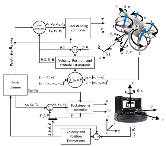
Figure 1.
Multi-robot coordinates and control structure. Subscript “d” means “desired”.
The torque and thrust coefficients of the rotor (motor+propeller) are and , respectively; is the rotor’s inertia and d is the distance between the center of the rotor to the quadrotor’s center of mass.
2.2. Wheeled Robot Model
In the literature, the kinematic model of two-wheeled differential-drive robots is subjected to non-holonomic constraints, assuming that the wheels do not skid [,]. In this case, the robot motion is described as follows:
In the above equation, and represent the angle of rotation and angular velocity around the robot’s z-axis, respectively, and v is the linear velocity; r and d are the radius of the robot’s wheel and the distance between the robot’s rear wheels, respectively; and are the angular speeds of the right and the left wheels, respectively. In Figure 1, the body frame of the robot moves relative to an inertial frame O. Therefore, the kinematic equations in Cartesian coordinates are given as follows:
3. Backstepping Controller
3.1. Quadrotor Control
The backstepping (BS) controller is used in this work because of its capacity to solve the quadrotor’s essential stability problem. Most crucially, the control system ensures that the quadrotor’s position follows the specified path asymptotically [,]. The BS control system integrates both translation and rotation dynamics within a single control.
The adopted control law generates one thrust T and three torques and a timing law for the path parameter that guarantees convergence of the quadrotor’s position to the desired path , which is a function of a virtual arc . The control structures for the thrust and the torque vector are given by Equations (5) and (6), respectively:
where and are positive gains, and m is the mass of the quadrotor; is the third column of the rotation matrix (), and it indicates the direction of the quadrotor’s z body-axis. As a result, if equals the desired thrust direction (), the thrust force () will be equal to the desired thrust force (). Based on the desired thrust value () and thrust direction () in Equation (5), the thrust control law (T) is generated. Furthermore, the torque control law () is calculated in Equation (6) according to the angular acceleration (). Moreover, an arbitrary function () is used to define the dynamics of yaw angle.
where , , , and are positive gains; and are the first and second columns of the rotation matrix (), respectively. The skew symmetric matrix is represented by ; and denote the desired rotation matrix and quadrotor’s desired angular speed, respectively. Based on the BS controller, four error vectors ( to ) are defined. Those error vectors and derivatives are expressed as follows:
where and are the desired positions and velocities of the quadrotor, respectively. A time-dependent position error vector () can influence the initial position of the vehicle significantly. As a result, the control structure is distinguished by the fact that it is not directly related to the time factor associated with the first error. In other words, thrust (T) and torque vector () are not directly linked to (). In addition to the position error, the other errors are regulated by the saturation function () of (), which allows for bounded actuation. A detailed discussion of the stability proofs for these control laws can be found in [].
It is essential for the control algorithm to keep a well-defined control law to ensure that the vehicle follows the path. In order to achieve this condition, we have a timing law, which is obtained by adding the second time-derivative of the path parameter :
where and are the first and second partial derivatives of the desired path, respectively. The control law in Equation (8) drives to , which is calculated based on the path’s geometry. Any vector in tangent frame can be represented in inertial frame by the rotation matrix at any points where . For ease of use, most variables, which were previously defined, are listed in Table 1.

Table 1.
Parameters used in backstepping controller of a quadrotor. Subscript “d” means “desired”.
3.2. Ground Robot Control
A backstepping controller is adopted to accurately regulate the actuators that drive the robot from its current position to the desired position . The aim of the control is to minimize the following error:
As discussed in [], two control inputs (i.e., and ) are considered. Hence, the control law is implemented as follows:
where and are the desired linear velocity and angular velocity of the robot, respectively. The variables F and are calculated as follows:
where , and are the controller gains.
4. Motion Planning for Multi-Robot System
The purpose of this section is to introduce a new UV motion planning system based on potential forces. This system helps the robot (i.e., ground and aerial robots) follow a moving target within a dynamic environment containing obstacles. To achieve the desired target, an individual trajectory is generated for each robot, which has access to all the state information in one processor. In Section 3, the proposed control structure for each robot ensures that the tracking error will converge to zero, where tracking error of the ith robot is measured as:
where is a vector of the robot desired trajectory, and is its position with respect the inertial frame. The robot will continue to move towards its destination as long as there are no obstacles in its path. Alternately, the robot’s predefined path must be modified by feeding small variations in its motions. Essentially, the proposed approach generates a dynamic trajectory that allows the robot to track the target and avoid obstacles by generating attractive and repulsive potential forces.
4.1. Potential Attractive Force
The attractive force model is defined by the relative position and velocity vectors of two robots as follows:
The attractive force model includes two force components, and , as shown in Figure 2. The first component, , propels the robot toward the target, shortening the distance between them. The second component, , keeps the robot moves at the same velocity as the target. The relative position between the robot and the target is given by , and the relative velocity is given by . Each force component can be tuned correctly by the gains and . Figure 2 illustrates the relationship between the attractive force components and the relative position and velocity of the robot to the target in a 2-dimensional space. Normally, this system is applied to a ground robot that is following another robot, and the concept can also be extended to cover UAVs in the third dimension. The attractive force for each motion direction (i.e., x, y, and z) can be given as follows:
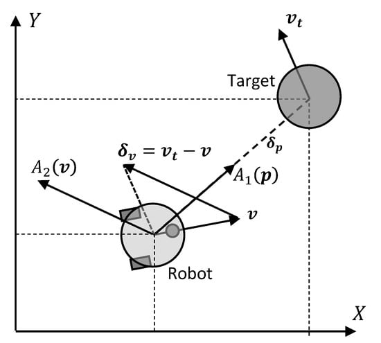
Figure 2.
Attractive force in 2D space.
4.2. Potential Repulsive Force
When a robot encounters an obstacle, it will also be provided with an extended potential force to detour and avoid collision. Considering and are the position and the velocity of an obstacle which can be obtained on-line, then the relative velocity between the robot and the obstacle is , and the relative position is , as shown in Figure 3. Then, the value of in the direction from the robot to the obstacle is given by:
where is a unit vector pointing from the robot to the obstacle. As shown in Figure 3, in the case where the robot is moving away from the obstacle as , no avoidance action is needed from the robot. In contrast, if , the robot requires a force to push it away from the obstacle. As a result, a model is used to generate appropriate repulsive forces. These forces are computed using the following function:
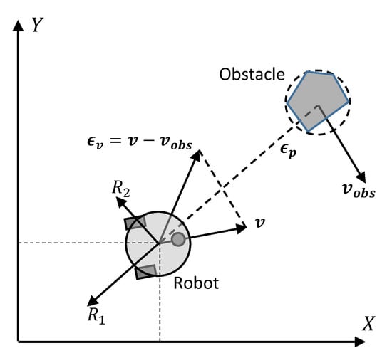
Figure 3.
Repulsive force in 2D space.
It can be seen in Figure 3 that is a force in the opposite direction of , which keeps the robot away from the obstacle. Moreover, is in the same direction of the perpendicular vector and acts as a steering force. Moreover, is a positive constant, is the shortest distance between the center of the robot and the center of the obstacle, and is the distance that the robot travels before it approaches zero, which is a function of a maximum deceleration and is given as follows:
In order to make the repulsive force model valid for multiple obstacles , the following relation is established:
6. Experimental Setup and Results
In this section, the proposed guidance, navigation, and control (GNC) system is implemented and evaluated by a multi-robot system. The performance of the adopted GNC system was evaluated in two different environments. The first environment was indoor and included three robotics platforms (i.e., two quadrotors and one ground robot), as shown in Figure 4. The second environment was implemented outdoor with another three drones and two car-like robots, as shown in Figure 4. An indoor system demonstrated robotic platforms with a motion capture system that provided real-time position and orientation. Based on several retro-reflective markers mounted on each robot, the motion capture system ran a software that defined rigid bodies. Each quadrotor executed the control algorithms with an onboard Intel Aero computer and the ground robot with a Raspberry Pi 3. In this study, quadrotor drones and ground robots were used to evaluate the performance of the backstepping controllers with the presence of disturbances. In addition in this stage, the drone’s ability to track a ground robot and avoid obstacles was tested in several experiments. Moreover, multi-robot missions were performed outdoors in different scenarios for surveying and monitoring, as illustrated in Figure 5. A Pixhawk autopilot was used to test the proposed control and navigation algorithms. The guidance system and communication between robots were built on a Raspberry Pi using the Robotics Operating System (ROS).
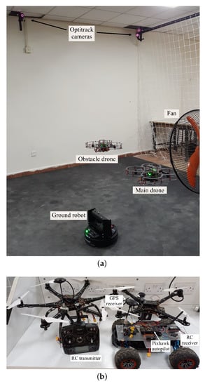
Figure 4.
Multi-robot systems: (a) indoor and (b) outdoor.
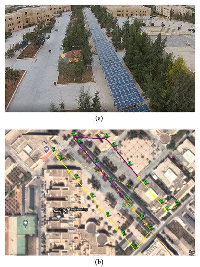
Figure 5.
Surveying mission at the campus of the Hashemite University: (a) a photo from the drone’s camera and (b) planned automatic mission on a map using sequence of way-points.
6.1. Backstepping and PID Comparison
Two experiments were implemented on each robot platform (i.e., quadrotor and ground robot). Well tuned PID controllers were adopted in the first experiment and compared with a similar scenario in the second experiment in which backstepping controllers were implemented, as discussed in Section 3. The performance of each platform was analyzed by computing the mean squared error (MSE) in positions and velocities. The results are listed in Table 2 for a quadrotor and Table 3 for a ground robot. The tables show the superiority of the backstepping controlled quadrotor and ground robot over PID controllers, particularly in high-speed paths. Figure 6 illustrates how the BS-controlled quadrotor was correctly tracking the predefined circular-path, whereas the PID-controlled quadrotor was diverging from the high-speed path. A similar performance was demonstrated by a BS-controlled ground robot on the squared-path. Figure 7 and Figure 8 clearly show the better performance of the backstepping controller for the quadrotor and the ground robot, respectively.

Table 2.
Mean squared errors (MSEs) for PID-controlled and BS-controlled quadrotors at different velocities.

Table 3.
Mean squared errors (MSEs) for PID-controlled and BS-controlled ground robots at different velocities.
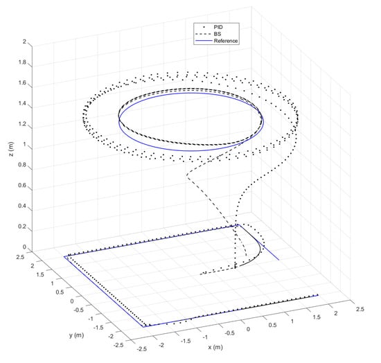
Figure 6.
A comparison between PID and BS controllers for quadrotors and ground robots (speed = 3 m/s).
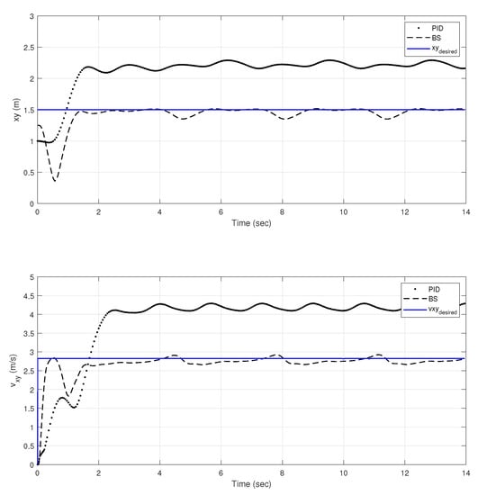
Figure 7.
A comparison between PID and BS controllers for quadrotors.
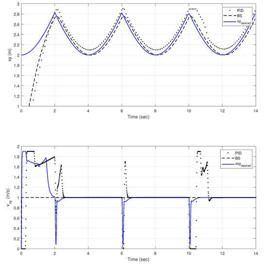
Figure 8.
A comparison between PID and BS controllers for ground robots.
Figure 9 shows the performance of quadrotors using both PID and BS controllers in an experiment on a squared-path with the addition of fan air flow as a disturbance, located at ( m) and directed toward the y axis. The PID-controlled quadrotor’s highest deviation from the reference route as a result of the disturbance was 42.4 cm, whereas the BS-controlled quadrotor’s highest position divergence was 5 cm. Therefore, based on the BS controller’s good results, it was implemented in ground robots and quadrotors for the best stability and tracking in multi-robot missions.
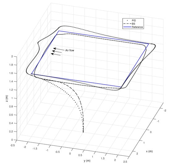
Figure 9.
A comparison between PID and BS controllers due to disturbance.
6.2. GNC System Performance
The backstepping controller was used along with the navigation system in Section 5 and the guidance system in Section 4 for a full guidance, navigation, and control (GNC) structure to demonstrate the performance of the quadrotors and ground robot in a network of multi-robots.
An indoor experiment was conducted to demonstrate a mission with two drones and one ground robot in order to to validate the overall GNC system. In this mission, a main drone was assigned to follow a ground robot that was traveling in a 4 × 4 squared path and followed with a 1.2 radius circle. A traveling drone was used to travel to point (−1.5, −1.5, 1.2) m and hover for a while. This point is one of the squared path’s corners that the tracking drone will pass through. Figure 10 depicts how the tracking drone avoided colliding with the traveling drone. Furthermore, it avoided the traveling drone once more while the last was approaching it, as shown in Figure 10.
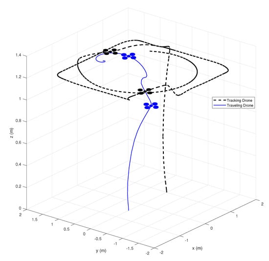
Figure 10.
Multi-robot mission of two drones and one ground robot.
The position and velocity of the two drones and the ground robot are illustrated in Figure 11. The figure shows that the tracking drone was precisely following the ground robot (i.e., m, m, and m/s), despite the fact that the obstacle avoidance task increased the error between them. The figure also shows how the tracking drone safely avoided the traveling drone on the 20th and 38th seconds and returned back to the desired path.
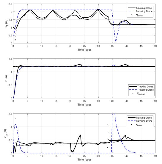
Figure 11.
Positions and velocities of two drones and one ground robot mission.
6.3. Outdoor Missions
Different missions were carried out in an outdoor environment to demonstrate the performance of a network of several drones and ground robots. The first mission scenario was carried out with three drones, one of which was assigned to lead the others on a predefined path, as illustrated in Figure 12. In this mission, three drones were launched from the same location, and the leading drone was tasked with following the predefined way-points while the other two drones followed it safely. Figure 13 illustrates the performance of the 140-s mission. The average lateral speed (i.e., in the xy direction) of each drone was approximately 10 m/s at different heights. The three drones completed the mission precisely and without any collisions, with the follower drones maintaining a nearly constant distance from the leading drone throughout the mission.
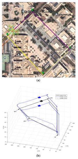
Figure 12.
Three-drone mission with one leading the others on a predefined path: (a) four way-points on a map (b) the trajectories of the three drones.
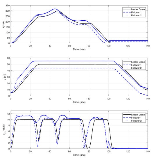
Figure 13.
Positions and velocities for the three drone mission.
In the second scenario, the three drones were programmed to survey an area of approximately 87,000 at the same time. Each drone was assigned to survey a portion of the area and photograph various locations, as shown in Figure 14. The mission was completed in approximately 160 s, with 24 photos of the entire area being taken, as illustrated in Figure 15. For sake of comparison, the same task was assigned to a single drone. The mission took approximately 330 s to complete using one drone.
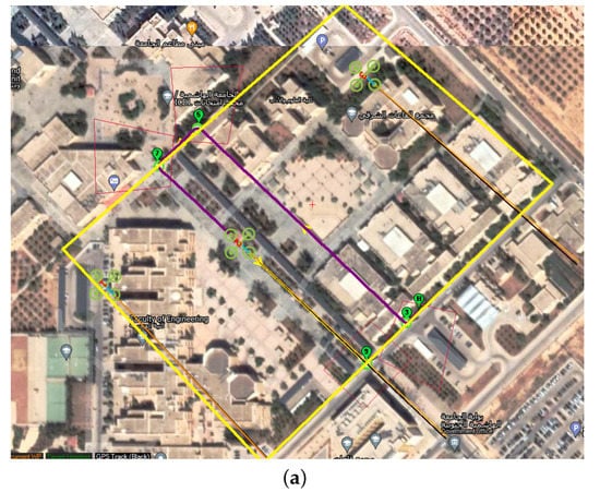
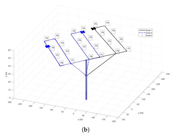
Figure 14.
Three drones surveying a large area: (a) surveyed area on a map, and (b) the path of each drone with the position of each picture (P).
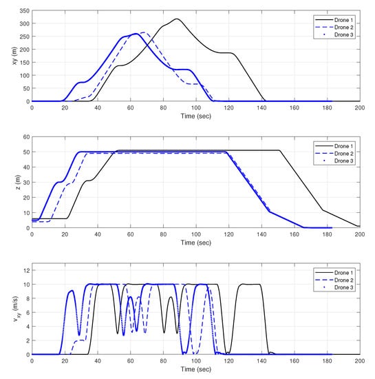
Figure 15.
Positions and velocities for the three drone mission.
The final outdoor scenario involved two ground robots performing a monitoring task. As shown in Figure 16, each robot was assigned to follow a different path on campus at the same time. As shown in Figure 17, each robot was moving at a speed of 5 m/s along a path that was approximately 1770 m long for the first robot and 2390 m for the second robot. As a result, the first ground robot completed its assignment in 390 seconds, whereas the second ground robot completed the mission in 490 s, taking into account the time it took to launch to the first way-point and return to the starting point.
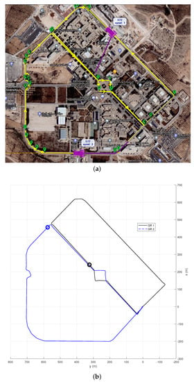
Figure 16.
Two ground robots in monitoring task: (a) robot’s path on a map using a sequence of way-points, and (b) the performed path of each robot.
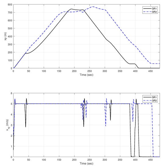
Figure 17.
Positions and velocities for the two ground robots mission.
The goal of the last two tasks was to evaluate the monitoring and inspection process using a group of aerial and/or ground robots rather than a single robot. The previous operations demonstrated that using a group of robots speeds up and improves the efficiency of the work. The robots demonstrated the ability to track way-points without colliding or intersecting with one another. These two experiments also demonstrated the ability of the navigation system to precisely locate the aerial and ground robots.
7. Conclusions
This work demonstrated the practical implementation of light-computing nonlinear algorithms for a full guidance, navigation, and control system for a network of quadrotor drones and ground robots. For the best path tracking and position and orientation stability, a backstepping controller was used. In order to implement a robust navigation system for control and guidance systems, nonlinear complementary filters were used to accurately estimate attitudes, positions, and velocities. For optimal robot guidance, a potential field method was used for tracking and obstacle-free path planning. Several indoor and outdoor experiments were conducted to assess the effectiveness of the GNC system on multi-robot missions. The results demonstrated the advantages of the proposed system in monitoring and inspection applications. This work paves the way for future efforts to improve the navigation system for higher-level perception in order to recognize and classify detected objects/events and infer some of their attributes. Another interesting aspect of the research is the use of the proposed GNC on the scales of swarms of quadrotors and ground robots in a challenging environment.
Author Contributions
Methodology, M.H.; validation, M.H. and A.A.M.; resources, M.H.; writing—original draft preparation, A.A.M.; writing—review and editing, M.H. and A.A.M.; supervision, M.H.; funding acquisition, M.H. All authors have read and agreed to the published version of the manuscript.
Funding
This work is supported by funding from the Royal Academy of Engineering, Transforming Systems through Partnership TSP1040.
Institutional Review Board Statement
Not applicable.
Informed Consent Statement
Not applicable.
Data Availability Statement
Not applicable.
Acknowledgments
This research is carried out in the context of the project “Drone-Assisted Micro Irrigation for Dry Lands in Jordan Using IoT Enabled Sensor Network (DAMIJO-IoT). All experimental results were obtained using all of the facilities provided by the Faculty of Engineering at the Hashemite University.
Conflicts of Interest
The authors declare no conflict of interest.
References
- BaniHani, S.; Hayajneh, M.R.M.; Al-Jarrah, A.; Mutawe, S. New control approaches for trajectory tracking and motion planning of unmanned tracked robot. Adv. Electr. Electron. Eng. 2021, 19, 42–56. [Google Scholar] [CrossRef]
- Li, P.; Wu, X.; Shen, W.; Tong, W.; Guo, S. Collaboration of heterogeneous unmanned vehicles for smart cities. IEEE Netw. 2019, 33, 133–137. [Google Scholar] [CrossRef]
- Mohamed, N.; Al-Jaroodi, J.; Jawhar, I.; Idries, A.; Mohammed, F. Unmanned aerial vehicles applications in future smart cities. Technol. Forecast. Soc. Chang. 2020, 153, 119293. [Google Scholar] [CrossRef]
- Ju, C.; Son, H.I. Multiple UAV systems for agricultural applications: Control, implementation, and evaluation. Electronics 2018, 7, 162. [Google Scholar] [CrossRef]
- Mutawe, S.; Hayajneh, M.; BaniHani, S.; Al Qaderi, M. Simulation of Trajectory Tracking and Motion Coordination for Heterogeneous Multi-Robots System. Jordan J. Mech. Ind. Eng. 2021, 15, 337–345. [Google Scholar]
- Aminifar, F.; Rahmatian, F. Unmanned aerial vehicles in modern power systems: Technologies, use cases, outlooks, and challenges. IEEE Electrif. Mag. 2020, 8, 107–116. [Google Scholar] [CrossRef]
- Salahat, E.; Asselineau, C.A.; Coventry, J.; Mahony, R. Waypoint planning for autonomous aerial inspection of large-scale solar farms. In Proceedings of the IECON 2019-45th Annual Conference of the IEEE Industrial Electronics Society, Lisbon, Portugal, 14–17 October 2019; Volume 1, pp. 763–769. [Google Scholar]
- Ismail, H.; Chikte, R.; Bandyopadhyay, A.; Al Jasmi, N. Autonomous detection of PV panels using a drone. In Proceedings of the ASME International Mechanical Engineering Congress and Exposition, Salt Lake City, Utah, USA, 11–14 November 2019; American Society of Mechanical Engineers: New York, NY, USA, 2019; Volume 59414, p. V004T05A051. [Google Scholar]
- Felsch, T.; Strauss, G.; Perez, C.; Rego, J.M.; Maurtua, I.; Susperregi, L.; Rodríguez, J.R. Robotized Inspection of Vertical Structures of a Solar Power Plant Using NDT Techniques. Robotics 2015, 4, 103–119. [Google Scholar] [CrossRef]
- Lee, D.H.; Park, J.H. Developing inspection methodology of solar energy plants by thermal infrared sensor on board unmanned aerial vehicles. Energies 2019, 12, 2928. [Google Scholar] [CrossRef]
- Rezk, M.; Aljasmi, N.; Salim, R.; Ismail, H.; Nikolakakos, I. Autonomous PV Panel Inspection with Geotagging Capabilities Using Drone. In Proceedings of the ASME International Mechanical Engineering Congress and Exposition, Virtual, Online, 1–5 November 2021; American Society of Mechanical Engineers: New York, NY, USA, 2021; Volume 85611, p. V07AT07A040. [Google Scholar]
- Franko, J.; Du, S.; Kallweit, S.; Duelberg, E.; Engemann, H. Design of a multi-robot system for wind turbine maintenance. Energies 2020, 13, 2552. [Google Scholar] [CrossRef]
- Iyer, S.; Velmurugan, T.; Gandomi, A.H.; Noor Mohammed, V.; Saravanan, K.; Nandakumar, S. Structural health monitoring of railway tracks using IoT-based multi-robot system. Neural Comput. Appl. 2021, 33, 5897–5915. [Google Scholar] [CrossRef]
- Roy, S.; Vo, T.; Hernandez, S.; Lehrmann, A.; Ali, A.; Kalafatis, S. IoT Security and Computation Management on a Multi-Robot System for Rescue Operations Based on a Cloud Framework. Sensors 2022, 22, 5569. [Google Scholar] [CrossRef]
- Kendoul, F. Survey of advances in guidance, navigation, and control of unmanned rotorcraft systems. J. Field Robot. 2012, 29, 315–378. [Google Scholar] [CrossRef]
- Verma, J.K.; Ranga, V. Multi-robot coordination analysis, taxonomy, challenges and future scope. J. Intell. Robot. Syst. 2021, 102, 1–36. [Google Scholar] [CrossRef] [PubMed]
- Yan, Z.; Jouandeau, N.; Cherif, A.A. A survey and analysis of multi-robot coordination. Int. J. Adv. Robot. Syst. 2013, 10, 399. [Google Scholar] [CrossRef]
- Zhilenkov, A.A.; Chernyi, S.G.; Sokolov, S.S.; Nyrkov, A.P. Intelligent autonomous navigation system for UAV in randomly changing environmental conditions. J. Intell. Fuzzy Syst. 2020, 38, 6619–6625. [Google Scholar] [CrossRef]
- Huang, L.; Song, J.; Zhang, C.; Cai, G. Design and performance analysis of landmark-based INS/Vision Navigation System for UAV. Optik 2018, 172, 484–493. [Google Scholar] [CrossRef]
- Qiu, Z.; Lin, D.; Jin, R.; Lv, J.; Zheng, Z. A Global ArUco-Based Lidar Navigation System for UAV Navigation in GNSS-Denied Environments. Aerospace 2022, 9, 456. [Google Scholar] [CrossRef]
- Kim, J.; Kim, S.; Ju, C.; Son, H.I. Unmanned aerial vehicles in agriculture: A review of perspective of platform, control, and applications. IEEE Access 2019, 7, 105100–105115. [Google Scholar] [CrossRef]
- Tzafestas, S.G. Mobile robot control and navigation: A global overview. J. Intell. Robot. Syst. 2018, 91, 35–58. [Google Scholar] [CrossRef]
- Cabecinhas, D.; Cunha, R.; Silvestre, C. A globally stabilizing path following controller for rotorcraft with wind disturbance rejection. IEEE Trans. Control Syst. Technol. 2014, 23, 708–714. [Google Scholar] [CrossRef]
- Mutawe, S.; Hayajneh, M.; BaniHani, S. Robust Path Following Controllers for Quadrotor and Ground Robot. In Proceedings of the 2021 International Conference on Electrical, Communication, and Computer Engineering (ICECCE), Kuala Lumpur, Malaysia, 12–13 June 2021; pp. 1–6. [Google Scholar]
- Kim, A.R.; Keshmiri, S.; Blevins, A.; Shukla, D.; Huang, W. Control of multi-agent collaborative fixed-wing UASs in unstructured environment. J. Intell. Robot. Syst. 2020, 97, 205–225. [Google Scholar] [CrossRef]
- Elkaim, G.H.; Lie, F.A.P.; Gebre-Egziabher, D. Principles of guidance, navigation, and control of UAVs. In Handbook of Unmanned Aerial Vehicles; Springer: Berlin/Heidelberg, Germany, 2015; pp. 347–380. [Google Scholar]
- Edlerman, E.; Linker, R. Autonomous multi-robot system for use in vineyards and orchards. In Proceedings of the 2019 27th Mediterranean Conference on Control and Automation (MED), Akko, Israel, 1–4 July 2019; pp. 274–279. [Google Scholar]
- Singh, Y.; Bibuli, M.; Zereik, E.; Sharma, S.; Khan, A.; Sutton, R. A novel double layered hybrid multi-robot framework for guidance and navigation of unmanned surface vehicles in a practical maritime environment. J. Mar. Sci. Eng. 2020, 8, 624. [Google Scholar] [CrossRef]
- Al-Fetyani, M.; Hayajneh, M.; Alsharkawi, A. Design of an executable anfis-based control system to improve the attitude and altitude performances of a quadcopter drone. Int. J. Autom. Comput. 2021, 18, 124–140. [Google Scholar] [CrossRef]
- Kurak, S.; Hodzic, M. Control and estimation of a quadcopter dynamical model. Period. Eng. Nat. Sci. 2018, 6, 63–75. [Google Scholar] [CrossRef]
- Hayajneh, M. Experimental validation of integrated and robust control system for mobile robots. Int. J. Dyn. Control 2021, 9, 1491–1504. [Google Scholar] [CrossRef]
- Mutawe, S.; Hayajneh, M.; Al Momani, F. Accurate State Estimations and Velocity Drifting Compensations Using Complementary Filters for a Quadrotor in GPS-Drop Regions. Int. J. Eng. Appl. 2021, 9, 317–326. [Google Scholar] [CrossRef]
Publisher’s Note: MDPI stays neutral with regard to jurisdictional claims in published maps and institutional affiliations. |
© 2022 by the authors. Licensee MDPI, Basel, Switzerland. This article is an open access article distributed under the terms and conditions of the Creative Commons Attribution (CC BY) license (https://creativecommons.org/licenses/by/4.0/).