Abstract
Core-shell materials are promising functional materials for fundamental research and industrial application, as their properties can be adapted for specific applications. In particular, particles featuring iron or iron oxide as core material are relevant since they combine magnetic and catalytic properties. The addition of an SiO2 shell around the core particles introduces additional design aspects, such as a pore structure and surface functionalization. Herein, we describe the synthesis and application of iron-based core-shell nanoparticles for two different fields of research that is heterogeneous catalysis and water purification. The iron-based core shell materials were characterized by transmission electron microscopy, as well as N2-physisorption, X-ray diffraction, and vibrating-sample magnetometer measurements in order to correlate their properties with the performance in the target applications. Investigations of these materials in CO2 hydrogenation and water purification show their versatility and applicability in different fields of research and application, after suitable individual functionalization of the core-shell precursor. For design and application of magnetically separable particles, the SiO2 shell is surface-functionalized with an ionic liquid in order to bind water pollutants selectively. The core requires no functionalization, as it provides suitable magnetic properties in the as-made state. For catalytic application in synthesis gas reactions, the SiO2-stabilized core nanoparticles are reductively functionalized to provide the catalytically active metallic iron sites. Therefore, Fe@SiO2 core-shell nanostructures are shown to provide platform materials for various fields of application, after a specific functionalization.
1. Introduction
Over the last decade, core-shell materials have received more attention in various fields of application [1]. Due to defined synthesis strategies, the core and shell of these composites can be tailored individually in size, shape, and functionality, which results in task-specific physico-chemical properties of the core-shell structure. Thus, core-shell particles have been utilized as a model catalyst in fundamental research, as for bioimaging, drug delivery, semiconductor processing, and as a coating admixture [1]. In addition, these materials are investigated for several industrial catalytic applications, e.g., esterification [2], ammonia decomposition [3], olefin hydrogenation [4], and Fischer-Tropsch synthesis [5], where the particles showed high structural stability.
Iron is a suitable core material in core-shell structures due to its large-scale availability and sustainability, as it can replace ecologically harmful or rare metals. In catalytic processes, such as the power-to-methane process, it is considered a promising replacement for nickel and cobalt as active materials, as it provides high selectivity in the methanation step [6] and flexibility toward various mixtures of H2/CO/CO2. The limited reactivity and the formation of different carbonaceous species under reaction conditions, however, is still a challenge, which is a matter of ongoing research [7,8]. For this purpose, the well-defined structure of Fe-based core-shell materials is highly promising in order to derive structure-activity relationships as the basis for design of stable, active, and selective catalysts. In particular, the core size can be controlled within narrow windows, providing the basis for fundamental studies using core-shell materials as model catalysts. The encapsulation within a SiO2 shell provides stabilization of the active nanoparticles against size change by sintering under reaction conditions and, thus, conserve the material structure [9]. Besides the catalytic properties, iron-based materials offer a variety of unique and tunable magnetic properties, such as super-paramagnetism and magnetic susceptibility, tunable by size and shape of the nanoparticles. The super-paramagnetic properties of nanoscale iron oxide in particular, makes those materials highly interesting to be applied as transport vehicles, since the magnetic particles only interact with an external magnetic field. Therefore, the particles can be moved by the external field, but do not tend to agglomerate and, thus, blocking of the transport pathway is avoided. To exploit this field of application, the magnetic cores are encapsulated in SiO2 as well, which can easily be functionalized depending on the application. Such materials are successfully applied in medical research with emphasis on cancer treatment [10], which is very encouraging. Recently, we report the application in waste water treatment as well, where we show that various types of contaminants can be removed upon suitable functionalization of the SiO2 surface [11].
The broad application potential of core-shell materials relies on a synthesis strategy, which allows precise and independent control of all material properties. The core size, for instance, plays a crucial role, since the magnetic properties are defined by the size and shape of the crystallite entities inside the core, whereas the catalytic properties are governed by the core morphology and, thus, the active sites at the core surface. The pore structure of the SiO2 shell, on the other hand, provides access of reactants to the catalytically active core or the surface to be functionalized by surface-active compounds [12]. At the same time, the shell acts as a steric barrier against core sintering in catalytic applications [13], if the pores are sufficiently small. Consequently, a step-wise bottom-up synthesis strategy is applied for material design [8,9], starting with the synthesis of well-defined iron oxide nanoparticles with a controllable size. In the second step, these nanoparticles are encapsulated within an SiO2 shell of a determined pore structure and thickness. Finally, the materials are functionalized according to the desired application. The first two synthesis steps are, thus, independent on the final application, while only the third step is performed according to the desired property formation. This approach also opens the possibility for scale-up of material synthesis, since the specific treatment steps are the final ones in the step-wise approach. Therefore, the procedure is rather universal, except for the final functionalization step.
In this contribution, we emphasize the potential of nanostructured Fe@SiO2 core-shell materials for application in both catalysis and waste water treatment. The aim is to demonstrate the versatility of such materials for a very broad spectrum of applications and the respective correlation between application and material properties. We focus on Fe@SiO2 materials synthesized via a simple and scalable procedure, whose properties can be easily tuned and can be functionalized, according to the targeted application. In particular, the iron core size is varied in order to use the materials as model catalysts for fundamental studies on particle size effects in CO2 methanation. In addition to that, the magnetic properties also depend on the core size, which is of high importance for the design of a process for magnetic separation. The SiO2 shell is modified regarding the thickness, pore structure, and surface functionalization. Since it acts as steric stabilization of the active core, a certain minimum thickness is required for the structural stabilization effect. On the contrary, diffusion is hindered for thick shells, which can be overcome by designing an appropriate pore structure. For surface functionalization, the pore structure and the size of the core-shell particles define the available specific surface required for immobilization of the desired compounds, such as ionic liquids (IL).
We present the synthesis procedure and options for tuning the properties of functionalized Fe@SiO2 core-shell materials. Comprehensive characterization by X-ray diffraction (XRD), transmission electron microscopy (TEM), N2-physisorption, vibrating sample magnetometer (VSM) measurements, and temperature-programmed reduction (TPR) provides insights into the material properties. We explore the material performance for both the catalytic CO2 hydrogenation and water purification, which demonstrates that the particles can act both as a solid catalyst and magnetic support, respectively, after suitable modification and functionalization. For catalytic applications, the core material is modified by applying a thermochemical treatment under H2 atmosphere to achieve a metallic state of the Fe core, while the SiO2 shell stays unaffected. For water purification, the core remains unchanged, while we modify the SiO2 shell by immobilization of polyoxometalate-based ionic liquids (POM-IL), which are effective in waste water purification [11]. Thus, we demonstrate the universal applicability of such Fe@SiO2 core-shell materials for catalysis and waste water treatment, after suitable functionalization of either core or shell.
2. Results and Discussion
In the following, the terms ‘iron’ or ‘Fe’ are related to the active component, which can mainly be described by FexOy after synthesis. During a process dependent activation procedure for applications in catalysis, the active iron species will be either converted to elemental iron or iron carbides. The synonymous use of the superordinate terms ‘iron’ or ‘Fe’ simplify the following comments. Sample codes are used for differentiation of the materials reported in this paper. The notation xFe(y)@SiO2 describes iron-based core@shell materials with an Fe mass fraction of x wt.% and an average core size of y nm. For example, 15Fe(6)@SiO2 represents materials with an Fe mass fraction of 15 wt.%, and an average core size of 6 nm.
2.1. Characterization of Core and Shell Morphology
In Figure 1A, the adsorption and desorption isotherms of the N2-physisorption experiments are shown, which reveal a uniform and defined pore size distribution in the core-shell materials, irrespective of differences in core size and shell thickness of the Fe@SiO2 materials studied. The isotherms can be described by a combination of Type 1 and 4 of the classification by Brunauer et al. [14]. The steep slope in the adsorption isotherms at < 0.02 (Figure 1A, inset) indicates Type 1 behaviour by adsorption in the micropores within the SiO2 shell. The slopes of the adsorption isotherms for > 0.5 and the hysteresis between adsorption and desorption indicate Type 4 isotherms and, thus, multilayer adsorption and capillary condensation, most likely due to large pores between the SiO2 particles. The volumetric pore width distribution shown in Figure 1B indicate a maximum pore size of ca. 6.0 Å and a broad distribution toward larger pores, which underlines the amorphous structure of the SiO2 shell. Hence, the porosity of the silica shell and, thus, accessibility of the core for catalytic applications is given for synthesis gas, as the kinetic diameter of H2, H2O, CO2, CO, and CH4 varies between 2.3 and 3.8 Å, which is smaller than the pore size [15,16]. The analysis of the mesopore region ( > 0.5), shown in Figure S5 (see Supplementary Materials), reveals a broad pore size distribution, which points toward the interparticle spaces being responsible for providing a mesopore surface, rather than mesopores within the SiO2 shell. This is underlined by the obtained surface area of ca. 200 m²/g, evaluated via the Brunauer-Emmet-Teller (BET) method, which corresponds to the specific surface area of solid, non-porous SiO2 particles of about 11.5 nm in diameter (density amorphous SiO2 = 2200 kg m³). Note that interparticle spaces measure 12 nm on average, while the overall average size of the core-shell particles range from 13 to 20 nm, which can be observed in TEM micrographs, as well (see Figure 3). In addition, the pore volume given through the micropore structure, calculated via the Horvath-Kawazoe (HK) method, is approximately 10% compared to the mesopore volume calculated from the Barrett-Joyner-Halenda (BJH) method, both shown in Table 1.
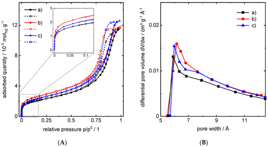
Figure 1.
Results of N2-physisorption experiments. (A) Adsorption (filled symbols) and desorption (open symbols) isotherms of as-made Fe@SiO2 core-shell particles: (a) 13Fe(8)@SiO2, (b) 15Fe(6)@SiO2, (c) 15Fe(4)@SiO2, and (B) pore width distribution for the corresponding micropore regime (insert left) using the Harvardt-Kawazoe (HK) method.

Table 1.
Results of N2-physisorption experiments. The average micropore width and micropore volume calculated via the Harvardt-Kawazoe (HK) method, interparticle pore width , and pore volume calculated via Barrett-Joyner-Halenda (BJH) method, and a specific surface area calculated via the Brunauer-Emmet-Teller (BET) method for different core-shell materials.
Figure 2 shows patterns from powder X-ray diffraction (PXRD) of selected Fe core-shell samples. The overall signal intensity is rather low due to absorption of the X-ray beam by the silica shell and the small crystallite size. Nevertheless, the signals relating to γ-Fe2O3, α-Fe2O3, and SiO2 can be identified and marked in Figure 2, according to the literature [17]. The intensity of α-Fe2O3 reflexes is low compared to γ-Fe2O3 and overlapping with γ-Fe2O3 is observed. Therefore, α-Fe2O3 reflexes are not considered for further evaluation and discussion. The major phase in the core-shell materials is represented by nanoscale γ-Fe2O3 with the most pronounced reflexes at the lattice planes defining Miller indices (hkl) of hkl = (022), (311), and (511), according to the literature [7,18]. All respective PXRD patterns show a broad reflex at ca. 26° 2θ identified as amorphous SiO2 from the particle shell. Though Fe3O4 has similar crystalline structures and lattice parameters, this phase is excluded by previous 57Fe Mössbauer experiments for similar synthesized core-shell material [7].
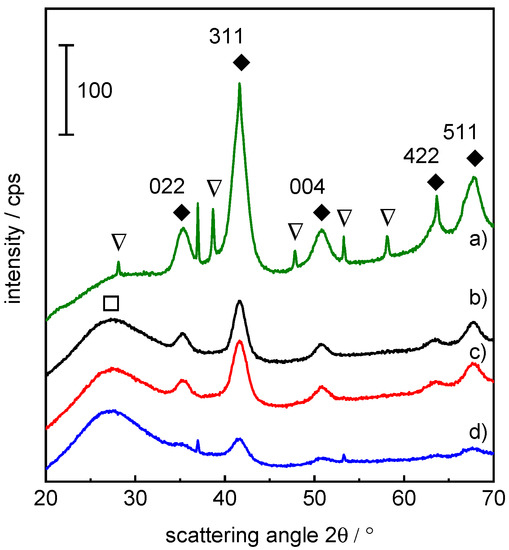
Figure 2.
Powder X-ray diffraction (PXRD) patterns with reflexes assigned to γ-Fe2O3 (filled diamond), α-Fe2O3 (open triangle), and SiO2 (open square) of selected as-prepared core–shell catalysts: (a) 42Fe(6)@SiO2, (b) 13Fe(8)@SiO2, (c) 15Fe(6)@SiO2, (d) 15Fe(4)@SiO2, (hkl) indices refer to γ-Fe2O3.
The crystallite sizes (Table 2) for the selected catalyst samples were estimated using the Scherrer Equation (Equation (1)) with the mean size of crystalline domains , the Scherrer shape factor , X-ray wavelength , line broadening at half of the maximum intensity (FWHM) in radians , and the Bragg angle .
Table 2.
Fe crystallite phase derived from PXRD and average crystallite size of γ-Fe2O3 at (hkl) = 311 estimated via Scherrer Equation.
For estimation of the crystallite sizes of γ-Fe2O3 via Scherrer Equation, the most pronounced reflex at 42° 2θ, related to hkl = (311), was used. Hence, the crystallite sizes calculate to 4.5, 5.1, and 4.6 nm for core-shell materials of 15Fe(4)@SiO2, 15Fe(6)@SiO2, and 13Fe(8)@SiO2, respectively. This value describes roughly the size of the regularly ordered crystal structures inside of the Fe2O3 core nanoparticles and is highly dependent on the Bragg angle as well as the FWHM value. Reflex broadening, due to small Fe2O3 nanoparticulate cores, and low signal intensity, due to partial X-ray absorption by the SiO2 shell, causes the FWHM value to only be roughly estimated. Additionally, one has to mention that the Scherrer Equation is only valid for spherically shaped crystals with sizes <100 nm and cubic unit cells. Best results are achieved for small reflective angles, as Bragg angle dependent broadening of reflexes, which is the basis for the Scherrer Equation, was never observed experimentally [19]. The deviation between the crystallite size derived from the Scherrer equation and the core size from TEM analysis can be explained by the fact that the core represents an aggregate of smaller crystallites, which, in particular, holds for a core size of 8 nm. Additionally, it can be affected by strain within the particle and non-ideal crystallinity. For materials (b) to (d), the slight deviation in crystallite sizes from expected core sizes, is mainly due to the uncertainties mentioned above. It also has to be mentioned that PXRD is a bulk analysis method covering the whole ensemble, while TEM is restricted to a limited sample size.
2.2. Design of Core-Shell Morphology
Typical TEM micrographs shown in Figure 3, Figures S1–S3 (see Supplementary Materials) depict individual encapsulated iron core-shell particles of a uniform, spherical shape. The dark dots indicate Fe-oxide nanoparticles and the dark grey area around relates to SiO2, indicated by arrows in Figure 3a, respectively. Hence, the synthesis provides core-shell particles in a defined shape and shell thickness. By variation of readily accessible synthesis parameters, one can adjust the three most important properties for the core-shell structures, nominal core size, shell thickness, and, thus, metal loading. In conclusion, a narrow particle size distribution for the iron-oxide cores can be achieved, which is illustrated by box-plots in Figure 3b and summarized in Table 3 and Table S1 (see Supplementary Materials). The core-shell materials are characterized by two morphological degrees of freedom, namely the core size and the overall particle size , which can be obtained from TEM micrographs. One important design parameter, the Fe mass fraction , can be either calculated gravimetrically from the yield in the synthesis procedure or via Equation (2) if the molar mass of iron and iron oxide , the density of the core , and of SiO2 , as well as the shell porosity is known. Both morphological degrees of freedom can be tailored by respective adjustment of synthesis parameters, which is offered by the unique bottom-up synthesis approach. In particular, the average core size can be controlled in a range between 3.5 to 8 nm, while the shell thickness can be varied between ca. 3 and 6 nm, which are both accessible by TEM experiments. Therefore, the Fe mass fraction ranges between 6 and 46 wt.%.
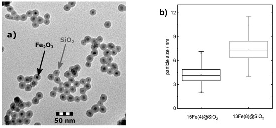
Figure 3.
(a) TEM micrograph of 13Fe(8)@SiO2 core-shell particles (as-made), (b) box-plots of particle size distribution of selected core-shell particles calculated from TEM micrographs.
Table 3.
Average core size of as-made Fe@SiO2 core-shell particles and the respective SiO2 shell thickness measured from TEM micrographs: iron content and specific surface area calculated from measured values via Equations (2) and (3).
For catalytic application in syngas reactions, the iron cores change in size during reduction and carbidization under reaction conditions, due to removal of oxygen from or the incorporation of carbon into the lattice. Furthermore, the core entities are supposed to change shape upon thermochemical treatment, in order to form thermodynamically stable, and most likely almost spherical aggregates. In particular, the specific active surface area of the core is the most relevant parameter for catalysis, which can either directly be measured by chemisorption experiments or derived from the core size by assuming the particle shape. Since chemisorption is not capable of providing reliable data on the active surface area of nanostructured core-shell materials, we determine the average core diameter via TEM for a sufficiently large number of particles counted. The specific surface area of the iron core after H2 reduction can be estimated from the average core size obtained from TEM prior to reduction and the density of iron via Equation (3). For derivation of Equation (3), see Table S3 in Supplementary Materials. Note that the core size change is accounted for by volume reduction during the reduction process from Fe2O3 to metallic Fe0. The specific active surface areas obtained are listed in Table 3 and Table S1 (see Supplementary Materials). The values are directly correlated to the catalytic activity, as the availability of active sites is proportional to the surface area when assuming constant active site density.
The magnetization versus external magnetic field curves (- curves) of selected samples measured by the vibrating sample magnetometer (VSM) technique are shown in Figure 4A and in Figure S6 (see Supplementary Materials). The - curves show no hysteresis effects, which confirms the superparamagnetic behavior of the γ-Fe2O3 cores. - curves of superparamagnetic particles can be well described by Langevin functions (see Equation (4)). Here, is the magnetization, is the saturation magnetization, is the external magnetic field, is the vacuum permeability, is the Boltzmann constant, is the absolute temperature, and is the total magnetic moment of the γ-Fe2O3 core.
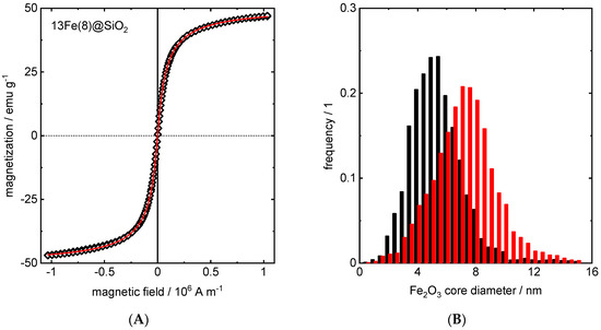
Figure 4.
(A) Example for the - curve of as-made 13Fe(8)@SiO2 core-shell particles measured by VSM (open diamonds) together with fitted curve (red line) calculated via superposition of Langevin functions. (B) Core size distributions of two selected as-made Fe@SiO2 core-shell particles (black: 15Fe(4)@SiO2, red: 13Fe(8)@SiO2) fitted from corresponding - curves with a superposition of Langevin functions.
Since the core magnetic moment is proportional to the volume of the core, the - curve is dependent on the core size . By fitting the measured - curves to a superposition of individual Langevin functions (see Equation (4)), each corresponding to a specific , the core size distribution for each sample can be determined, which is shown for two selected samples in Figure 4B. The comparison of the fitted and measured - curves exhibits good agreement, as shown in Figure S6 (see Supplementary Materials), which validates the significance of the fitted average core sizes listed in Table 4. From the fitted - curves, the corresponding susceptibilities, which define the reaction of the cores to external magnetic fields, are estimated and shown in Figure S7 (see Supplementary Materials). It can be observed that the values depend on both the external magnetic field and the core size. The initial magnetic susceptibilities, which are defined as the susceptibilities near the zero field, correlate with the core size as well (see Table 4).
Table 4.
Average core size and initial magnetic susceptibility fitted from the - curve with a superposition of Langevin functions.
In this work, core sizes are determined with three different methods: estimation from PXRD reflexes via Scherrer equation, direct evaluation of TEM image data, and fitting of experimental - curves by superposition of Langevin functions. Although the general agreement is reasonable, one should keep in mind both strengths and limitations of the individual techniques. In the Scherrer equation-based evaluation, it is assumed that the peak broadening is solely due to the crystallite size, thereby neglecting real effects as discussed above. In addition, possible superposition of reflexes from different phases within one sample may lead to deviations. For TEM evaluations, on the other hand, only a limited number of particles from the individual TEM images contributes to the result, while the other two methods provide average information for a much larger number of particles. Furthermore, for small encapsulated particles, precise determination of the core size is limited by contrast and resolution in TEM evaluations. In the fitting procedure of the experimental - curves, the saturation magnetization value of bulk γ-Fe2O3 has been used as an approximation, since full saturation of magnetization is not reached at room temperature in our measurements. This may potentially lead to a small deviation from the actual core size distribution in case of the existence of magnetically inactive surface layers or other imperfections, leading to a reduction of the magnetization to lower values than the bulk one. Considering the mentioned uncertainties, the results of all three methods agree well with each other regarding the observed trends in core size for the different samples.
Therefore, the sophisticated step-wise synthesis strategy provides the opportunity to tailor the properties of the core and shell independently of each other by adjusting the synthesis parameters (see Table S2). In particular, the core size can be controlled in a range between 3.5 to 8 nm on average and determines the magnetic and catalytic properties. The thickness and pore structure of the SiO2 shell can by controlled as well, which allows us to tailor the metal loading and specific pore volume and surface area of the composite core-shell materials. These properties are important for accessibility of the catalytically active cores, but also provide the basis for functionalization of the SiO2 surface. Therefore, the presented core-shell materials can be designed individually in order to fulfill the application specific requirements on structure, morphology, and functionalization.
2.3. Application in Catalysis
2.3.1. Temperature-Programmed Reduction (TPR)
Figure 5 shows the profiles for the reduction of Fe2O3 to Fe0 for samples with different Fe core sizes. The reduction temperatures for the transition of Fe2O3 to Fe3O4 (~300 °C) and for FeOOH to FeO (~450 °C) are identified according to the literature [20]. The multi-step transition above 500 °C associated with the reduction sequence Fe3O4 → FeO → Fe0 deviates from literature, though. Depending on the reduction pathway and the achieved degree of reduction below 500 °C, either the reduction of Fe3O4 to FeO (560–590 °C) or the reduction of FeO to Fe0 (625–655 °C) is more pronounced. This corresponds to the observations in Figure 5, which indicates a correlation between the hydrogen consumption below 500 °C with the consumption pattern above this temperature, being qualitative. Zielinski et al. observed the variation in intensity as well as a shift toward lower temperatures of different reduction regimes as they added a small amount of water to the inlet gas stream [21]. Since we have proven our gas supply to be water-free by mass spectrometry measurements, we assume that the SiO2 shell leads to a confinement effect. In other words, the water formed during reduction might accumulate in proximity of the core due to restricted diffusion through the shell toward the bulk flow. This causes equivalent effects compared to moisture fed to the sample. A confinement effect in selectivity was previously reported by Ilsemann et al. for methanation on cobalt-based core-shell particles [22], and, thus, is also likely for the structural similar materials presented here. Additionally, the reduction of the core-shell particles starts at lower temperatures (~300 °C) in contrast to literature (~400 °C). Experiments from Zielinski et al. show a three-step reduction of Fe2O3 via FeOOH and FeO to Fe0 at high H2O/H2 ratios and corresponding low H2/Ar ratios in the feed gas stream. Additionally, Zielinski et al. found that there is a shift to lower temperatures and better resolution of the reduction steps for lower mass of iron oxide together with a low heating rate [21]. In comparison with those findings, the observed slight deviations in our experiments to literature reports can, thus, be explained by a combination of the relatively low metal loading of ca. 15 wt.% Fe (corresponding to a total amount of ca. 8 mg iron oxide in the experiment), the low H2/Ar ratio of 0.1 in the inlet gas stream, and the presence of H2O due to the potential confinement effect.
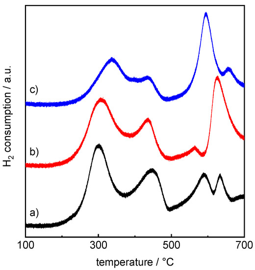
Figure 5.
TPR patterns of selected as-made Fe@SiO2 core-shell particles after initial drying at 200 °C in Ar flow (heating rate 2 K/min, 50 mLSTP/min Ar) for 2 h: (a) 13Fe(8)@SiO2, (b) 15Fe(6)@SiO2, and (c) 15Fe(4)@SiO2.
2.3.2. CO2 Hydrogenation
Figure 6 shows formation rates for the main (a and c) and by-products (b and d) for CO2 hydrogenation with two different core sizes after 12 h of time-on-stream (TOS), respectively. The main reaction can be determined as a reverse water-gas-shift (RWGS) reaction, as CO is the main product in the measured temperature range. The 8-nm core-shell material (13Fe(8)@SiO2) with CO formation rates of 1.2, 3, and 5.5 as well as the 4-nm core-shell material (15Fe(4)@SiO2) with CO formation rates of 0.9, 2.8, and 7 are both comparable at temperatures at 350, 370, and 390 °C, respectively, in terms of RGWS activity. The 15Fe(4)@SiO2 material on the contrary provides a three times higher amount of methane as a side product at 350 °C, compared to 13Fe(8)SiO2. Additionally, one has to mention that the amount of ethylene stays unaffected from temperature over the temperature range for 15Fe(4)@SiO2, while it increases for 13Fe(8)@SiO2. Both core-shell materials have the side products methane, ethylene, and higher (C3+) by-products in common, which are formed to a lesser extent and show no distinct temperature dependence, contradicting expectations from the Arrhenius Equation. The CO formation rate, on the other hand, shows distinct temperature dependency, which allows us to roughly estimate the apparent activation energy . The obtained results of 45 and 60 kJ/mol fit well with literature values in the order of 50 kJ/mol [23] for both catalysts tested, respectively. The selectivity toward CO increases significantly from 75% to 98% for 15Fe(4)@SiO2 and from 91% to 98% for 13Fe(8)@SiO2 between 350 and 390 °C. It has to be mentioned, though, that no stable catalyst activity is achieved after 12 h TOS, due to dynamic restructuring and Fe carbide formation (see Supplementary Materials, Figure S4). This issue is stated to be highly dependent on particle size and, thus, is still a matter of current research [7]. Though the value of the activation energy might be affected by the dynamic change of the catalyst under reaction conditions, the order of magnitude indicates the absence of severe mass transport limitations through the SiO2 shell. In summary, the selected core-shell material shows applicability as a RWGS catalyst for hydrogenation reactions with a very high selectivity toward CO at temperatures above 370 °C.
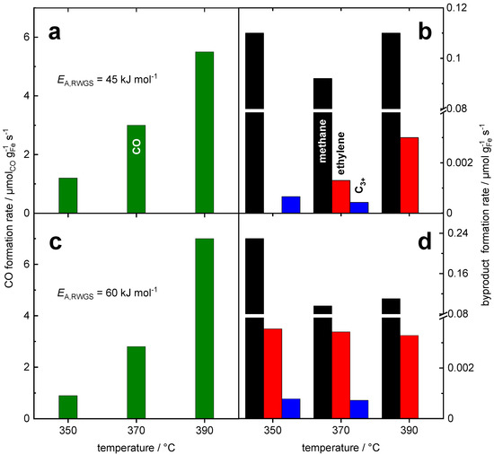
Figure 6.
Product formation after 12 h for CO2 hydrogenation at temperatures between 350 and 390 °C with two different core-shell materials: 13Fe(8)@SiO2 (a and b), 15Fe(4)@SiO2 (c and d); left (a and c): formation rate of CO via RWGS reaction, right (b and d): formation rate of methane and C2+ compounds, conditions: H2/CO2 = 4.5, p = 1 bar, = 100 mLSTP/min.
The defined core-shell architecture leads to new material features with respect to reduction characteristics and catalytic properties. The confinement effect introduced by the amorphous SiO2 shell, which can be observed from catalyst reduction behavior, certainly plays an important role regarding catalyst performance and will be exploited in future research. Furthermore, the defined material structure of the core encapsulation by an SiO2 shell introduces new possibilities toward material characterization, in particular the tracking of individual cores during transformation upon catalytic reactions [9]. Beyond these applications as model catalysts for derivation of fundamental understanding of structure-activity relationships in catalytic processes, the tailoring of those structures for optimization of activity, selectivity, and stability provides high potential for intensification of catalytic applications.
2.4. Application as Magnetic Support in Water Purification
Patent Blue V (PBV) dye removal was quantified by UV-Vis spectroscopy (Figure 7) and it was observed that the magnetic polyoxometalate-supported ionic liquid phase (magPOM-SILP) composites 2 and 4 removes more than 99% of the dye, while the non-modified reference composites 1 and 3 show only a negligible (~6%) removal after stirring for 24 h. Note that no leaching of any components into the aqueous phase was observed after the treatment by using inductively coupled plasma atomic emission spectroscopy (ICP-AES) and carbon, hydrogen, and nitrogen (CHN) elemental analysis.
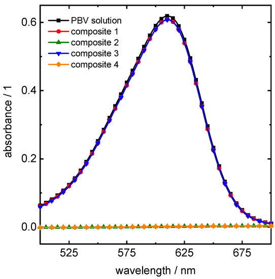
Figure 7.
Water purification with magPOM-SILP composites: UV-Vis absorption spectra of Patent Blue V (PBV) (black) with reference composites 1 and 3 (red and blue) and magPOM-SILP composites 2 and 4 (green and orange), which show total removement of PBV from solution, through 0.0 adsorption of irradiated light.
The high affinity of the POM-IL to interact with the organic compounds of the dye is attributed to the large, hydrophobic Q7 cations of the POM-IL, whereas the anionic counterpart binds strongly to the SiO2 surface, resulting in IL immobilization [11]. The magnetic core adds a further functionality to the composite material reported herein, which is, thereby, capable of removal by a magnetic field and, therefore, pressure-driven filtration is not required as a separation principle. We assume that a well-designed process allows us to reduce the energy input required for separation, which needs further research effort, though. In addition to that, the magnetic core renders the composite material being a transport vehicle for transportation of the dye by means of the magnetic field. This principle is also applicable to other organic compounds and may, thus, allow us to control transport trajectories of molecules.
Furthermore, no effect of the core size on purification efficiency was observed for the magPOM-SILP composites 2 and 4. This agrees well with the results from magnetic measurements, where similar properties are observed for nominal core sizes of 4 and 6 nm. The optimization of the core size with respect to its magnetic properties is a matter of ongoing research, though, since a dependency between core size and magnetic properties is expected for more significant size differences. In particular, the separation rate needs to be increased in order to apply these materials in realistic scenarios, where magnetic separation competes with conventional filtration. Therefore, the use of electromagnets is most likely, rather than permanent magnets, since they offer tunable and switchable field strength and gradient for task-specific design. For this purpose, the core size-dependent magnetic susceptibility, due to ferrimagnetism of the core, is of particular importance. Furthermore, those materials are also capable of removing a broad variety of further pollutants from waste water, e.g., micro plastics, as we reported recently [11].
3. Materials and Methods
3.1. Synthesis of Iron-Based Core-Shell Materials
Spherical silica encapsulated iron oxide nanoparticles were prepared using an adapted reverse water-in-oil microemulsion method. For the oil phase, 100 mL cyclohexane (VWR Chemicals, AnalaR NORMAPUR®) was put into a round-bottom flask and heated to 50 °C. Depending on the desired iron nanoparticle size, a defined amount of polyoxyethylene (10) cetyl ether (Brij® C10, Sigma Aldrich/Merck, Germany) or polyoxyethylene (20) cetyl ether (Brij® 58, Sigma Aldrich/Merck) was added to the organic phase. Subsequently, 5 mL of an aqueous FeCl3 solution (ACROS Organics, Germany, p.a.) were added to the mixture under continuous stirring. The required amount of surfactant and the corresponding concentration of the FeCl3 solution are listed in Table S2 (see Supplementary Materials). After 30 min of homogenization, 3 mL of hydrazine hydrate (aqueous solution, 35 wt.%, Sigma Aldrich/Merck, Germany) was added dropwise and slowly to the solution, which was followed by continuously stirring for 1 h. The color of the solution changed from bright yellow to dark brown, which indicates the formation of iron nanoparticles. To encapsulate the obtained iron oxide nanoparticles in silica, a defined amount of tetraethyl orthosilicate (TEOS, Merck, Germany, p.a.) was added to the suspension, which was followed by 3 mL of a 5 M aqueous ammonia solution (Carl Roth, 30 wt.%, ROTIPURAN®, Germany). The added volumetric amount of TEOS directly affects the metal loading of the catalysts, which is listed in Table S2. The mixture was stirred continuously for 2 h. Afterward, the microemulsion was destabilized with the addition of 2-propanol (VWR Chemicals, technical, Germany) and centrifuged at 8000 rpm for 15 min. The obtained particles were washed several times in 2-propanol, dried over night at 80 °C, and calcined at 420 °C for 4 h (ramp 2 K/min).
3.2. Preparation of magPOM-SILP
4.01 g of as-prepared 15Fe(6)@SiO2 (composite 1) or 15Fe(4)@SiO2 (composite 3) core shell particles were dispersed in 50 mL of a primarily synthesized 3.36 mM POM-IL solution ((Q7)8[α-SiW11O39] dissolved in acetone) and gently shaken for 5 min. After removal of the solvent under reduced pressure, acetone (50 mL) was added, and the shaking/solvent removal procedure was repeated three to five times. A solid, free-flowing brown powder of magPOM-SILP was obtained after vacuum drying for each composite, respectively. The POM-IL loading corresponds to 20 wt.% with a quantitative yield of 5.00 g [11]. The corresponding magPOM-SILP materials are named as composite 2 (composite 1 + POM-IL) and composite 4 (composite 3 + POM-IL) in this contribution.
3.3. Material Characterization
Bright field TEM micrographs were taken by a Zeiss TEM 109 equipped with a CCD camera. For sample preparation, a droplet of ethanol (VWR, 96% Ph. Eur.) solution containing the sample powder (ca. 0.5 mg/mL) was deposited on a carbonized Cu grid, followed by evaporation of ethanol. For each material, a size distribution of the iron core and SiO2 shell was derived from at least 300 particles. PXRD was performed on an X’Pert Pro-MPD (PANalytical) with Cu-Kα radiation (45 kV, 40 mA). The diffractograms were recorded in 2θ mode from 5 to 80° with a step width of 0.033° and a time of 10 s per step.
Temperature programmed reduction (TPR) and N2-physisorption experiments of the as-prepared catalysts were performed on a Micromeritics 3Flex device. For N2-physisorption experiments, adsorption isotherms including the micropore regime and desorption isotherms were recorded. Micropore analysis was done using the inbuilt Horvath-Kawazoe method. Catalyst preparation for N2-physisorption was performed using a Micromeritics SmartVacPrep for degassing the samples at 1 mbar and 240 °C for 2 h. Before the TPR measurements, the samples were pretreated by drying under an Ar stream from RT to 200 °C at a rate of 5 K/min and a hold time of 2 h. For TPR measurements, the temperature was increased from 50 to 900 °C at a constant ramp of 5 K/min under a constant stream of 10% H2/Ar at 40 mLSTP/min. The H2 consumption was measured with a thermal conductivity detector (TCD).
The VSM measurements were performed by a LakeShore 7300 Series VSM. The - curves of the Fe-based materials were measured at 295 K. The maximum applied magnetic field was 1.035 × 10⁶ A/m (1.3 × 10⁴ Oe). The fitting with a superposition of Langevin functions was done by a self-developed MATLAB program based on the least squares method.
3.4. Catalytic Performance Test
Prior to the catalytic experiments, as-made core-shell particles were pressed at 200 MPa and granulated by crushing and sieving. Furthermore, 150 mg of as-prepared core-shell samples was used for catalytic experiments by taking a grain size of 125 to 200 µm. The catalytic tests are performed in a 0.25 in. stainless-steel tubular reactor equipped with two K-type thermocouples for monitoring the temperature of the catalyst bed and reactor wall. In-situ reduction and activation of the as-prepared core-shell samples were performed directly before the experiments. For reduction, a continuous flow of 100% H2 was applied to the sample at 400 °C (p = 1 bar, = 180 mLSTP/min) for 12 h. Subsequently, the reduced catalyst was conditioned under CO hydrogenation at 350 °C (molar ratio H2/CO = 4.5, p = 1 bar, = 100 mLSTP/min) for 24 h and, afterward, under CO/CO2 hydrogenation at 350 °C (CO:CO2 = 1:1, H2/C = 4.5, p = 1 bar, = 100 mLSTP/min) for 12 h to achieve a defined and reproducible catalyst state. This is necessary, due to the well-known dynamic changes of iron phases during synthesis gas reactions [6]. In the following, CO2 hydrogenation was performed at 350, 370, and 390 °C (H2/CO2 = 4.5, p = 1 bar, = 100 mLSTP/min) for 12 h. Between each CO2 hydrogenation test, the catalyst was treated in CO and CO/CO2 hydrogenation at 350, 370, or 390 °C, as described before, to maintain a defined and reproducible catalyst state. The reaction products were analyzed using an on-line gas chromatograph (Thermo Fischer, sample volume 20 µl, volume flow 5 mLSTP/min, flame ionization detector (FID) for hydrocarbons, thermal conductivity detector (TCD) for COx compounds).
3.5. Application as Magnetic Support Material for Water Purification
Water purification tests were performed using the magPOM-SILPs (composites 2 and 4) for removal of organic pollutants often found in water samples. As reference materials, composites 1 and 3 were used and were treated identically to composites 2 and 4 to compare purification capacity with and without IL functionalization of the SiO2 surface. Aqueous samples (5 mL) of the pollutant at health-relevant concentrations were prepared, and the magPOM-SILP 2/4 or the reference composites 1/3 (50 mg) were dispersed in the polluted sample and magnetically stirred. Here, triphenylmethane (trityl) dye Patent Blue V (PBV) was used as a model for textile dye pollutants. Aqueous solutions of PBV were stirred with magPOM-SILP composites 2/4 and reference composites 1/3, respectively, using the standard experimental procedure described above. After stirring for 24 h, the magnetic particles were removed by using a permanent magnet and the solution was analyzed by UV-Vis spectroscopy, sensitive for quantification of the dye concentration.
4. Conclusions
In summary, we demonstrate a convenient synthesis strategy for iron-based core-shell nanoparticles and their utilization in two different applications, namely heterogeneous catalysis and waste water treatment. By adjustment of synthesis parameters, e.g., Fe and SiO2 precursor amount, the control of the Fe core size, and Fe loading is possible, while the encapsulation process does not affect the properties of the iron-oxide core. In contrast, the pore structure of the silica shell is rather independent on the material synthesis parameters. The accessibility of the catalytic active core for synthesis gas is still given for use in catalytic hydrogenation, and was proven in this contribution. However, the control of the pore geometry and volume is important for surface functionalization, as the proper uptake of the functionalization agent into the pores and to the surface is strictly required for the specific application, e.g., water treatment. Together with the magnetic properties of the core, e.g., magnetic susceptibility, the core-shell material can be utilized as a magnetic separable support of cleaning agents (ionic liquids) for use in water purification, as shown in this and other contributions [11].
Importantly, we demonstrate the versatility of the bottom-up synthesis strategy of Fe@SiO2 materials, using application in heterogeneous catalysis and waste water treatment as examples. In particular, the first two synthesis steps, namely the core synthesis and the SiO2 encapsulation, are independent of the desired application and, thus, universal. Therefore, cheap production as bulk material becomes realistic, if continuous particle formation is applied [24]. The functionalization of the Fe@SiO2 precursor materials in step three is specific to the application and requires individual approaches. The chosen examples in this contribution, though, prove that even very different requirements from application on material properties can be fulfilled by suitable functionalization procedures.
Supplementary Materials
The following are available online at https://www.mdpi.com/2073-4344/11/1/72/s1. Table S1: Average core size of as-made Fe@SiO2 core-shell particles and the respective SiO2 shell thickness measured from TEM micrographs: iron content and specific surface area calculated from measured values. Table S2: Mass of surfactants, concentration of FeCl3 solution, and volume of TEOS for defined synthesis of Fe based core-shell particles. Table S3: Derivation Equation (3): specific surface area of Fe cores derived from Fe2O3 core diameter (measured via TEM). Figure S1: TEM micrographs of as-made core-shell particles with an average core diameter of 4 nm. Figure S2: TEM micrographs of as-made core-shell particles with an average core diameter of 6 nm. Figure S3: TEM micrographs of as-made core-shell particles with an average core diameter of 8 nm. Figure S4: Time resolved product formation rates during CO2 hydrogenation. Figure S5: Pore width distribution for corresponding mesopore regime (p/p0 > 0.5) calculated from desorption isotherm using the Barrett-Joyner-Halenda (BJH) method. Figure S6:- curves of as-made Fe@SiO2 core-shell particles measured by VSM together with fitted curves with a superposition of Langevin functions. Figure S7: Core magnetic susceptibility vs external magnetic fields of as-made Fe@SiO2 core-shell particles fitted from the corresponding - curve with a superposition of Langevin functions.
Author Contributions
Conceptualization: C.Z. and R.G. Core-shell material synthesis, electron microscopy, N2-physisorption, TPR experiments and evaluation, catalytic performance test experiment and evaluation: C.Z. VSM experiment and evaluation: R.S. and U.H. magPOM-SILP preparation, water purification experiment, and evaluation: A.M. and C.S. Manuscript original writing and editing: C.Z. Manuscript revision: R.G., C.S., and U.H. All authors have read and agreed to the published version of the manuscript.
Funding
This research received no external funding.
Acknowledgments
We thankfully acknowledge Samuel Blessing (AC II, Ulm University) for executing PXRD measurements.
Conflicts of Interest
The authors declare no conflict of interest.
References
- Chaudhuri, R.G.; Paria, S. Core/Shell Nanoparticles: Classes, Properties, Synthesis Mechanisms, Characterization, and Applications. Chem. Rev. 2012, 112, 2373–2433. [Google Scholar] [CrossRef] [PubMed]
- Feyen, M.; Weidenthaler, C.; Güttel, R.; Schlichte, K.; Holle, U.; Lu, A.-H.; Schüth, F. High-Temperature Stable, Iron-Based Core-Shell Catalysts for Ammonia Decomposition. Chem. Eur. J. 2011, 17, 598–605. [Google Scholar] [CrossRef] [PubMed]
- Tai, Z.; Isaacs, M.A.; Durndell, L.J.; Parlett, C.M.; Lee, A.F.; Wilson, K. Magnetically-separable Fe3O4@SiO2@SO4-ZrO2 core-shell nanoparticle catalysts for propanoic acid esterification. Mol. Catal. 2018, 449, 137–141. [Google Scholar] [CrossRef]
- Hudson, R.; Riviere, A.; Cirtiu, C.M.; Luska, K.L.; Moores, A. Iron-iron oxide core-shell nanoparticles are active and magnetically recyclable olefin and alkyne hydrogenation catalysts in protic and aqueous media. Chem. Commun. 2012, 48, 3360–3362. [Google Scholar] [CrossRef] [PubMed]
- Ni, Z.; Qin, H.; Kang, S.; Bai, J.; Wang, Z.; Li, Y.; Zheng, Z.; Li, X. Effect of graphitic carbon modification on the catalytic performance of Fe@SiO2-GC catalysts for forming lower olefins via Fischer-Tropsch synthesis. J. Colloid Interface Sci. 2018, 516, 16–22. [Google Scholar] [CrossRef] [PubMed]
- Kirchner, J.; Baysal, Z.; Kureti, S. Activity and Structural Changes of Fe-based Catalysts during CO2 Hydrogenation towards CH4—A Mini Review. ChemCatChem 2020, 12, 981–988. [Google Scholar] [CrossRef]
- Kirchner, J.; Zambrzycki, C.; Baysal, Z.; Güttel, R.; Kureti, S. Fe based core-shell model catalysts for the reaction of CO2 with H2. React. Kinet. Mech. Catal. 2020, 131, 119–128. [Google Scholar] [CrossRef]
- Kirchner, J.; Zambrzycki, C.; Güttel, R.; Kureti, S. CO2 Methanation on Fe Catalysts Using Different Structural Concepts. Chem. Ing. Tech. 2020, 92, 603–607. [Google Scholar] [CrossRef]
- Strass-Eifert, A.; Sheppard, T.L.; Damsgaard, C.D.; Grunwaldt, J.-D.; Güttel, R. Stability of Cobalt Particles in and outside HZSM-5 under CO Hydrogenation Conditions Studied by Ex Situ and In Situ Electron Microscopy. ChemCatChem 2020, 12, 1–13. [Google Scholar] [CrossRef]
- Jahangirian, H.; Kalantari, K.; Izadiyan, Z.; Rafiee-Moghaddam, R.; Shameli, K.; Webster, T.J. A review of small molecules and drug delivery applications using gold and iron nanoparticles. Int. J. Nanomed. 2019, 14, 1633–1657. [Google Scholar] [CrossRef] [PubMed]
- Misra, A.; Zambrzycki, C.; Kloker, G.; Kotyrba, A.; Anjass, M.H.; Castillo, I.F.; Mitchell, S.G.; Güttel, R.; Streb, C. Water Purification and Microplastics Removal Using Magnetic Polyoxometalate-Supported Ionic Liquid Phases (magPOM-SILPs). Angew. Chem. Int. Ed. 2020, 59, 1601–1605. [Google Scholar] [CrossRef] [PubMed]
- Cerff, M.; Morweiser, M.; Dillschneider, R.; Michel, A.; Menzel, K.; Posten, C. Harvesting fresh water and marine algae by magnetic separation: Screening of separation parameters and high gradient magnetic filtration. Bioresour. Technol. 2012, 118, 289–295. [Google Scholar] [CrossRef]
- Arnal, P.M.; Comotti, M.; Schüth, F. High-Temperature-Stable Catalysts by Hollow Sphere Encapsulation. Angew. Chem. Int. Ed. 2006, 45, 8224–8227. [Google Scholar] [CrossRef] [PubMed]
- Brunauer, S. The Adsorption of Gases and Vapors Vol.1: Physical Adsorption; Princeton University Press: Princeton, NJ, USA, 1943. [Google Scholar]
- Ismail, A.F.; Khulbe, K.; Matsuura, T. Gas Separation Membranes, 1st ed.; Springer: Cham, Switzerland, 2015. [Google Scholar]
- Matteucci, S.; Yampolskii, Y.; Freeman, B.D.; Pinnau, I. Materials Science of Membranes for Gas and Vapor Separation—Chapter 1: Transport of Gases and Vapors in Glassy and Rubbery Polymers; John Wiley & Sons Ltd.: Hoboken, NJ, USA, 2006; pp. 1–47. [Google Scholar]
- Sun, C.; Mao, D.; Han, L.; Yu, J. Effect of preparation method on performance of Cu-Fe/SiO2 catalysts for higher alcohols synthesis from syngas. RSC Adv. 2016, 6, 55233–55239. [Google Scholar] [CrossRef]
- Singh, B.P.; Kumar, A.; Areizaga-Martinez, H.I.; Vega-Olivencia, C.A.; Tomar, M.S. Synthesis, characterization, and electrocatalytic ability of γ-Fe2O3 nanoparticles for sensing acetaminophen. Indian J. Pure Appl. Phys. 2017, 55, 722–728. [Google Scholar]
- Monshi, A.; Foroughi, M.R.; Monshi, M.R. Modified Scherrer Equation to Estimate More Accurately Nano-Crystallite Size Using XRD. World J. Nano Sci. Eng. 2012, 2, 154–160. [Google Scholar] [CrossRef]
- Cornell, R.M.; Schwertmann, U. The Iron Oxides: Structure, Properties, Reactions, Occurences and Uses; Wiley-VCH GmbH & Co. KGaA: Weinheim, Germany, 2003. [Google Scholar]
- Zielinski, J.; Zglinicka, I.; Znak, L.; Kaszkur, Z. Reduction of Fe2O3 with hydrogen. Appl. Catal. A Gen. 2010, 381, 191–196. [Google Scholar] [CrossRef]
- Ilsemann, J.; Straß-Eifert, A.; Friedland, J.; Kiewidt, L.; Thöming, J.; Bäumer, M.; Güttel, R. Cobalt@Silica core-shell catalysts for hydrogenation of CO/CO2 mixtures to methane. ChemCatChem 2019, 11, 4884–4893. [Google Scholar] [CrossRef]
- Loiland, J.A.; Wulfers, M.J.; Marinkovic, N.S.; Lobo, R.F. Fe/γ-Al2O3 and Fe-K/γ-Al2O3 as reverse water-gas shift catalysts. Catal. Sci. Technol. 2016, 6, 5267–5279. [Google Scholar] [CrossRef]
- Straß, A.; Maier, R.; Güttel, R. Continuous Synthesis of Nanostructured Co3O4@SiO2 Core-Shell Particles in a Laminar-Flow Reactor. Chem. Ing. Tech. 2017, 89, 963–967. [Google Scholar] [CrossRef]
Publisher’s Note: MDPI stays neutral with regard to jurisdictional claims in published maps and institutional affiliations. |
© 2021 by the authors. Licensee MDPI, Basel, Switzerland. This article is an open access article distributed under the terms and conditions of the Creative Commons Attribution (CC BY) license (http://creativecommons.org/licenses/by/4.0/).