Abstract
Electrospun nano-fibers exhibit two significant properties: a high surface-to-volume ratio and a relatively defect-free molecular structure. Due to the high surface-to-volume ratio, electro-spun materials are well suited for activities requiring increased physical contact, such as providing a site for a chemical reaction or filtration of small-sized physical materials. However, electrospinning has many shortcomings, including difficulties in producing inorganic nanofibers and a limited number or variety of polymers used in the process. The fabrication of nanofiber bundles via electrospinning is explored in this analytical study and the relationship between all effective electrospinning parameters and the relative abundance of various fiber morphologies. Numerous variables could impact the fabrication of nanofibers, resulting in a variety of morphologies such as uniform, entangled, individual beads, beads-on-string, etc. Therefore, adequate ambient conditions and selecting the appropriate polymer and solvent for achieving a homogenous polymer solution and uniform with desired nanofiber properties for different applications of electro-spun materials are examined. Finally, the promising applications of nano-fine fibers in various fields achieved via electrospinning are studied in this paper.
1. Review on Electrospinning and Electrostatic Phenomenon
Electrospinning as a subset of electrostatic spraying (i.e., the behavior of electrically driven liquid jets) dates back all the way back to 1745, when Bose utilized high electric potentials to generate aerosols from fluid drops [1]. Subsequently, Formhals invented electrospinning as a fiber spinning technique, using an electrostatic force via introduction of experimental setup for the production of polymer filaments, in the early 1930s by publishing series of US patents.
The invention, named “method and apparatus for preparing artificial threads”, was patented in 1934 as well as other advanced spinning techniques. However, some practical problems persisted, such as fiber drying and collection, until he filed his first patent, which addressed spinning difficulties at the time. A movable thread was used to collect the stretched threads. He explained the spinning of cellulose acetate fibers using acetone as the solvent in his patent [2,3].
Electrostatic phenomena are induced by electrons’ relative ease of movement in different materials. Electrostatics is classified into two broad categories: conduction and induction. Induction is a transient state of matter in which electrons are either drawn to or repelled by a neighboring charged material [4]. On the other side, conduction occurs when a charged object establishes physical contact with a neutral object. When excess electrons are transferred from a charged object to a neutral object, the objects gain the same charge [5]. Electrostatic charges exert forces (F) calculated using Coulomb’s law:
where k is the Coulomb constant, and are the electrostatic charges, and d is the distance between and . The forces between opposite charges cause water droplet deformation [6].
Electrospinning is a general term that refers to producing fibers by using an electric current to draw charged threads of polymer solutions. Typically, the fibers produced by this process have a thickness of hundreds of nanometers. Electrospinning is a method that combines the characteristics of dry spinning and electrospraying of fiber [7]. The method is ideal for the processing of complex and large molecules because it does not require the use of chemistry coagulation or high temperatures [8,9,10,11,12,13].
2. Overview of Nano-Fiber Bundles Fabrication Methods and Electrospinning
Nanofibers are considered fibers with a diameter of less than 1000 nm; they can be created through a variety of processing techniques. Thus far, the nanofiber-making techniques include direct drawing, magneto-spinning, extrusion, melt-blowing, hard templating, soft-templating, self-assembly, lithography, centrifuge spinning, hydrothermal/solvothermal, ball milling, chemical vapor deposition, and electrospinning. Among them, electrospinning outperforms due to its numerous advantages, including controllable fiber diameter (from tens of nanometers to a few microns), ability to fabricate a wide variety of materials (natural and synthetic polymers, metals, ceramics, composites, and sol-gels), and a variety of fiber morphologies (porous, dense, core-sheath, hollow, spiral, side-by-side, nanoparticles, nanorods, nanowires, nanosheets, and nanobelts), capable of large scale production [8,9,10,11,12].
Nanofibers deposit layer upon layer on a metal collector plate, due to the electrostatic force between charges, resulting in the formation of a nanofibrous mat [14,15,16]. The solvent and polymer properties, as well as effective ambient parameters of the electrospinning process, have an essential effect on the structural morphology of the nanofibers. The working distance, viscosity, conductivity, polymer solution, nozzle geometry, humidity, and temperature, as well as the applied voltage, are all effective parameters [17]. It is vital to optimize and differentiate the dominant effective parameters for morphology optimization of solution-based electrospun nanofibers.
The filament is a term that refers to an infinitely long fiber, while filament yarn refers to a yarn that is formed of one or more filaments running the length of the yarn. A fiber bundle presents an assembly of fibers that are aligned in a specific direction. In comparison, the yarn is a continuous length of any interlocked fibers. With all being mentioned, electrospun nanofibers are mainly fabricated as randomly oriented fiber mats, limiting their applications. While converting nanofibers into continuously twisted bundles, i.e., nanofiber yarns can increase their mechanical strength; however, the process still has its challenges. From electrospun nanofibers, two types of continuous nanofiber bundles could be created. Non-twisted nanofiber bundles are referred to as filament yarns in this context, whereas twisted continuous fiber bundles exhibit all yarn characteristics [18]. Correlations between ambient electrospinning parameters, solution/solvent properties, and the relative abundance of various fiber morphologies result in the formation of different nanofiber bundle structures, categorized in Figure 1.
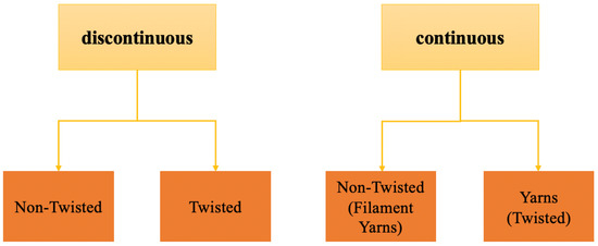
Figure 1.
Nanofiber bundle categories. Adapted from ref. [18].
3. Electrospinning Categories
Electrospinning could be used to produce nanofibers in two ways: needle-free or needle-based. Needle-based electrospinning begins with a polymer solution contained in a tightly sealed tank, which both restrict and prevent solvent evaporation. The needle-based method is critical because it enables the handling of a wide variety of materials, including those that are extremely volatile [19]. Needle-based electrospinning offers the following advantages: process versatility, including the ability to process fibers with multi-axial and core-shell structures. Additionally, the needle-based approach allows for precise monitoring of the flow rate, minimizes solution waste, and utilizes a small number of jets. Numerous benefits have contributed to the needle-based method’s widespread usage [20].
On the other side, needle-free electrospinning enables large-scale material processing. Using a rotating or stationary base, a starting polymer solution is used to produce nanofibers [21]. The needle-free electrospinning process, on the other hand, is incapable of producing diverse fibers. Additionally, numerous process variables, including the flow rate, cannot be controlled [22].
4. Electrospinning Process and Principles
Electrospinning is a method that uses submicron fibers to create an impermeable non-woven fabric by forcing a liquid jet with a millimeter diameter through an electric field-induced nozzle.
Two primary instabilities that act on the polymer solution jet that influences fiber formation in electrospinning are: first, the axisymmetric varicose instability (Plateau–Rayleigh instability), and, second, the non-axisymmetric whipping instability. The Rayleigh instability stems from the surface tension of the solution that tends to minimize the surface area by making individual droplets. The non-axisymmetric whipping instability occurs as a result of an existing electrostatic field. This causes the spiraling motion of the jet, which is necessary to develop ultra-finished fibers, to bend and stretch it. The essential factors associated with solution characteristics and operating conditions or extrinsic conditions predominantly account for the features of these instabilities. These factors are mainly attributed to the solution conductivity, viscosity, electrostatic field strength, and surface tension [23,24].
In general, the electrospinning fiber forming process can be observed and split into three distinct stages: prolate droplet deformation (Taylor cone) and jet initiation, whipping or bending instability, and fiber deposition. The general setup for electrospinning is shown in Figure 2. The electrostatic charge at the nozzle’s tip is critical for the creation of a Taylor cone at the point of ejection of a single jet of fluid [15]. The electric field’s acceleration and thinning of the jet, combined with radial charge repulsion, cause the primary jet to break into several filaments; this phenomenon is referred to as “splaying”. The number of subsidiary jets produced determines the diameter of the resulting fibers. Under normal conditions, electrospinning’s fluid jet whipping is relatively fast, which is necessary for the development of nanofibers and layer by layer deposition on the metal grounded collector plate [25].
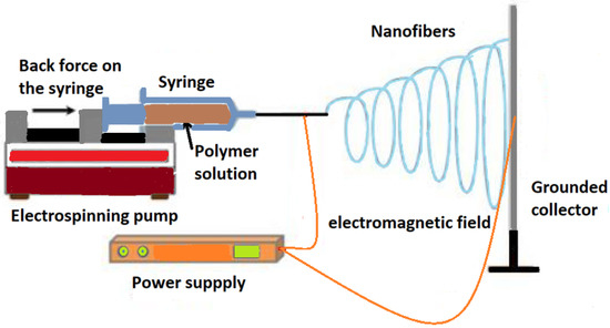
Figure 2.
General electrospinning setup. Reprinted from ref. [17].
In the following section, the three different stages of the fiber formation process and principles in electrospinning are explained:
4.1. Taylor Cone Formation
As the charged solution leaves the needle, a “Taylor cone” forms where the electrostatic repulsion is strong enough to cause the needle to eject a very fine stream of solution. In Figure 3, droplet deformation of polyethylene oxide solution and the cone–jet initiation at different time steps are shown. The time zero frame was chosen as the initial appearance of the jet. The voltage was applied for approximately 28 milliseconds before the jet rapidly dissipated. In frame 28 ms, the constant applied electric voltage had already partially changed the droplet of polyethylene oxide solution into a conical shape. The conical shape of the droplet becomes sharper and sharper, while the jet starts to form as the droplet obtains a more pointed tip at −2 ms timeframe. Finally, at timeframe 0 ms and onwards, the rounded tip inverts and then releases a jet of liquid. The cone–jet initiates the electrospraying process when the voltage exceeds the threshold. The Taylor cone denotes the theoretical limit of a cone–jet at the start of the electrospraying operation. The shape and size of the steady-state droplet at time 0 ms, +6 ms, and +32 ms are subject to changes if either the applied electrical potential or hydrostatic pressure changes. The formation of Taylor cone is a critical step in the electrospinning process. The formation of symmetrical vertices within the Taylor cone is likely to increase the solution’s velocity. Cone–jet beads result in the formation of beaded nanofibers [26].
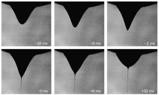
Figure 3.
Droplet deformation of polyethylene oxide solution captured at −28 ms, −8 ms, −2 ms, 0 ms, +6 ms, and +32 ms time-frames; the constant voltage was applied approximately 28 milliseconds before the cone–jet initiation (at −28 ms); cone–jet (Taylor cone) started at 0 ms onwards, culminating in the formation of the jet in the electrospinning process. Reprinted from ref. [27].
4.2. Whipping and Jet Instability
A strong electric field could deform a liquid with a finite electric conductivity into a conical shape due to the balance of surface tension and electric stresses. In contrast, the structure becomes unstable at the cone’s apex, and the thin jet structure replaces the resulting singularity. The electrospray is caused by the forced flow rate of the liquid inside the cone–jet structure, which is stable at certain applied voltage values—the electrospray is caused by the cone–jet structure collapsing into spherical droplets as a result of axisymmetric instabilities. However, due to electrostatic repulsion between the straight and bent sections of the jet, a lateral instability causes the jet to bend off its axis. When the whipping instability growth rate exceeds that of a jet breakup, the jet’s off-axis movement becomes a significant part of its evolution [28].
Polymer fibers are formed by substituting a polymer solution for a liquid and allowing the solvent to evaporate before drop breakup. The presence of lateral instability in the electrospinning process results in thinner fibers as the bending proceeds to stretch and thins the jet. However, in the majority of experiments, the whipping is notably chaotic, rendering an in-depth understanding of its properties and challenging structure [8,9,28].
4.3. Fiber Deposition
The formation of nanofibers is induced by an electrostatic force combined with a spinning mechanical force, which results in the continuous splitting of polymer droplets. Nanofibers deposit layer upon layer on the metal collector plate, resulting in the formation of a nanofibrous mat [14,15,16].
5. Solution-Based Electrospinning and Related Effective Parameters
Electrospinning using a solution requires a solvent to solubilize the polymer. As a result, selecting the appropriate solvent is critical for achieving a homogeneous polymer solution. The solution parameter is advantageous in deciding a solvent that is ideal for a particular polymer.
Numerous variables can impact the fabrication of nanofibers, resulting in a variety of morphologies such as uniform or entangled pattern structures with various cross-sections, beads-on-string structures, or individual beads. These critical factors include the type of polymer, the polymer molecular weight, the distribution of the polymer chain lengths, and the concentration of the polymer [29,30], solution conductivity, solution surface tension, solution viscosity, and solvent properties. Solvent properties contain boiling point, volatility, and dielectric properties [31]. Other extrinsic critical parameters affecting the final fiber morphology are indeed the applied voltage, collecting distance, and polymer solution flow rate [32]. Finally, ambient conditions such as high humidity, ambient temperature, and additional flow are all influential factors to be taken into account for electrospinning [8,9,33,34].
5.1. Concentration and Viscosity
As the polymer concentration increases, the viscosity increases gradually at first and then rapidly. Within a polymer solution, the intermolecular distance between polymer chains inside of a solution is so considerable that the interaction is considered to be quite weak [35].
As a result, the viscoelastic force in the polymer jet is negligible, allowing for the formation of a uniform fibrous structure. As the voltage is applied, the jet splits into separate charged sections. As a result of the high surface tension caused by solvent evaporation during spinning, these charged sections gradually transform into droplets or individual beads (see Figure 4). Similarly, increasing the polymer concentration results in a greater viscoelastic force and makes splitting the jet more difficult. Rather than dissolving the like-charged sections, electrostatic repulsion within the solution elongates the connections between charged sections, resulting in thinner filaments. Although the links between charged sections are thinner, the sections that are relatively thicker stretch thinner. Due to the surface tension created as the solvent evaporates during spinning, filaments tend to take on the shape of beads-on-string morphology (see Figure 5). As a result, increasing the polymer concentration results in uniform jet elongation and formation, resulting in a homogeneous and uniform fiber morphology (see Figure 6) [8,9,35,36]. In [17], vanadium pentoxide-based fibers were fabricated via electrospinning from various solutions containing sol-gel precursors of mixed with PVP, as an inorganic polymer. The concentration of the mixed PVP was increased to gain the best result. It was found that 0.45 (PVP): 4 () results in a uniform nanofiber mat as seen in Figure 6.
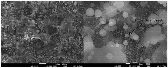
Figure 4.
An example of individual beads textile resulting from polymerized electro-spun with PVP + Graphene Oxide diluted in water. Reprinted from ref. [17].
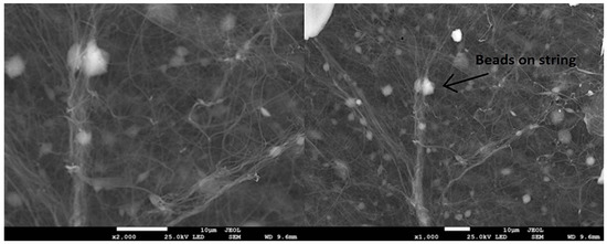
Figure 5.
An example of beads on strings of textile resulting from polymerized electro-spun with PVP + Graphene Oxide diluted in water. Reprinted from ref. [17].
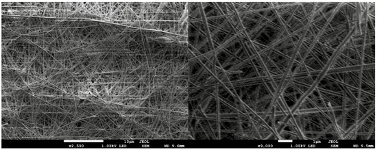
Figure 6.
An example of uniform textile resulting from polymerized electro-spun with PVP + Graphene Oxide diluted in water with a 0.45 (PVP):4 () ratio. Reprinted from ref. [17].
In general, the solution viscosity can be increased during electrospinning by either using a concentrated polymer solution or by increasing the polymer’s molecular weight. For example, doping polylactide solutions with high-molecular-weight polyethylene oxide increases the viscosity of polymer solutions [37]. Increased viscosity improves the jet stability, enabling the construction of multifilament yarns, individual fibers, and unidirectionally aligned fibers across a large area, or allowing the individual filaments to develop an ordered pattern [38]. According to literature, using polymers with a higher molecular weight and increasing the viscosity of the electrospinning solution results in a more stable jet [34].
5.2. Solvent
The process of electrospinning is highly dependent on solvent selection because the conductivity, viscosity, and surface tension of a solution are influenced by a number of solvent properties, such as conductivity, boiling point, vapor pressure, polarity, dipole moment, and dielectric constant. The volatility of the solvent should be proportional to the travel time of the jet, i.e., low volatility solvents result in a wet web structure. Similarly, rapid evaporation of highly volatile solvents causes the filament surface to cool and freeze, resulting in a porous surface on the web structure [39].
A solution’s electrospinnability can be increased by doping it with salt or using a solvent with a high dielectric constant and conductivity, which increases the spinning jet charge density. However, these same factors result in a shorter length jet, which should be avoided if the primary objective is to acquire a stable jet of greater length [40]. When it comes to solvent selection and its effect on the morphologies of final mats, multiple solvents could be utilized at the same time to achieve a more desired outcome. For instance, in [41], the fibers achieved in 15 wt% P84 a powder solution grade Polyimide (PI) solutions in a binary solvent system mixed with either N,N-Dimethylformamide (DMF), Dimethyl Sulfoxide (DMSO), N-Methyl-2-pyrrolidone (NMP), and N,N-Dimethylacetamide (DMAC) as the other pair of solvents were studied. In Figure 7, the average diameters (AD) of the fibers are reported. It is observed that the diameters of the fibers increase as the density and boiling point of the solvents increase. The fibers made from DMAC and DMSO mixtures had the largest diameters. The DMSO:DMF and DMAC:DMF solutions, on the other hand, exhibit poor electrospinnability. This behavior is due to DMF’s high volatility compared to the other two solvents and the difference in the values of the polymer’s solubility parameters in the solvent mixtures. Both of these factors resulted in clogged needles and disrupted the electrospinning process.
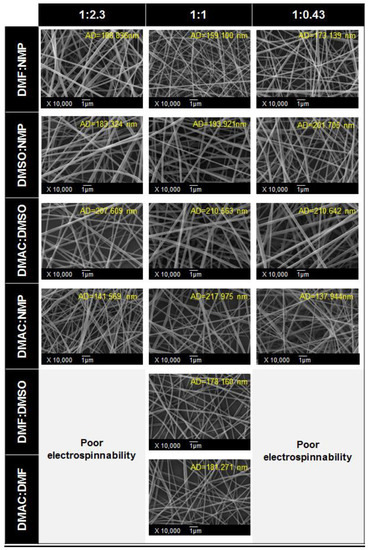
Figure 7.
FESEM morphologies of electrospun 15 wt% Polyimide (PI) solutions mixed with DMF, DMSO, NMP, and DMAC in binary solvent systems. Reprinted with permission from ref. [41].
5.3. Voltage and Electric Field
Traditionally, an increase in voltage results in an increase in the length of a stable jet during the electrospinning process. The increased length results from a stronger tangential electric field generated at the needle tip and a lower static charge density used to stabilize the electrospinning jet. The conventional effect, on the other hand, does not apply to all solutions. The inconsistency could be caused by various factors, including the solution’s dielectric property and conductivity. These variables have a more significant impact on jet stability [42].
The applied voltage has an effect on the jet’s bending and stretching stability, as a uniformly patterned web may result in some cases at higher voltages. However, the applied voltage is not the only critical factor to consider; other factors such as flow rate, jet traveling speed, and density must also be considered [43].
Typically, the electrospinning process utilizes direct current (DC) voltage; however, alternating-current (AC) voltage has been reported in a few papers and is not considered as safe as DC voltage, especially in high voltage situations [44,45,46]. When highly aligned fibers are desired, the reason for utilizing AC could be witnessed. When an alternating current power source is applied, a highly aligned web structure is gathered on a rotating mandrel [47].
Additionally, the magnitude and type of applied voltage applied have a significant effect on the jet Taylor cone initiation shape. It is only achieved and maintained within a specific window of applied voltage. Depending upon the solution and polymer properties such as type, molecular mass, concentration, as well as ambient conditions, the applied voltage shall be realized.
In Figure 8, FESEM images of electrospun nanofiber show how different electrical conditions could affect the final morphology with the same polymer, concentration, and solution properties. For different PVP solution concentrations (3.5% and 8%) at different voltages (8 kV and 15 kV), when the DC voltage setup changed to the pulsed mode, nanofibers were not achieved for 20 Hz (3.5% and 8% concentration) and 50 Hz (3.5% concentration) and, instead, the nozzle was reported to be in the dripping mode [48].
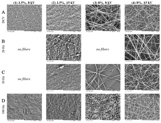
Figure 8.
FESEM images of PVP nanofiber mats (scale bar = 30 m); (A) DC voltage; (B) pulsed voltage at 20 Hz; (C) pulsed voltage at 50 Hz; (D) pulsed voltage 100 Hz. Reprinted from ref. [48].
5.4. Flow Rate
The solution flow rate must be reduced to a minimum point where the spinning jet can compensate for solution evaporation in order to maintain continuous fiber flow [49]. If the flow rate is higher than required, the solution will accumulate at the tip of the needle, preventing a normal Taylor cone from forming and eventually dripping off the tip. Occasionally, blockage of the needle or nozzle occurs as a result of the solvent rapidly evaporating, solidifying the droplet inside the needle or nozzle [50,51]. In [52], the solvent flow rate () and the polymer flow rate () of PCL-based solution was varied from 0.5 to 5 mL/h. The electrospun solution was only reported to have beads at certain rates, and there was no sign of nanofiber formation reported. The different fiber mythologies resulting from different flow rates could be observed in the FESEM images of the electrospun PCL-based solution in Figure 9.
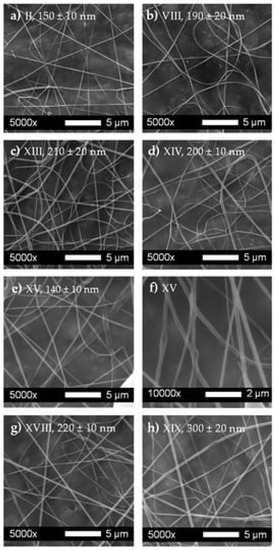
Figure 9.
FESEM images of electrospun PCL fibers and their corresponding average diameters; polymer flow rate () and the solvent flow rate () were varied from 0.5 to 5 mL/h. Run II and Run VIII had the same and = 1 mL/h but with different voltages; however, Run XIII corresponds to = 0.5 mL/h and = 5 mL/h, while Run XIV corresponds to = 1 mL/h = 0.5 mL/h. Run XV corresponds to = 1 mL/h and = 1 mL/h. In addition, finally, Run XVIII corresponds to = 3 mL/h and = 1 mL/h, while Run XIV corresponds to = 3 mL/h and = 3 mL/h. Reprinted from ref. [52].
5.5. Collecting Distance
The collecting distance between the tip of the nozzle and the collector is also a critical parameter in electrospinning. Collecting distance is proportional to the jet’s traveling time. Therefore, if the distance is too short, an entangled interconnected fiber mesh or films will most likely result due to the limited time available for the solvent to evaporate in the ambient air. As we increase the collecting distance in an electrospinning setup, the solvent has a greater chance of evaporating. Therefore, the increased evaporation of the solvent results in the formation of thinner nanofibers [17,53].
As can be seen in Figure 10, in [54], nanofibers with broad diameter distribution and smaller diameters (193 ± 81 nm) were reported, at the collecting distance of 20 cm from the nozzle to the collector. However, when the collecting distance changed to 15 cm, higher fiber distribution was reported with average higher fiber diameters (230 ± 36 nm).
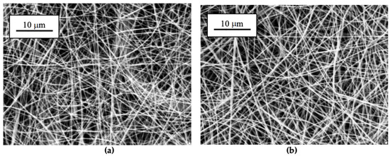
Figure 10.
FESEM images of two different morphologies of soy protein concentrate (SPC)/poly ethylene oxide (PEO) nanofibers collected on a V-shaped cardboard substrate two different needle-collector distances; (a) 20 cm and (b) 15 cm. Reprinted from ref. [54].
5.6. Nozzle Geometry
The nozzle geometry affects coaxial electrospinning because it controls the solutions’ flow rate, miscibility, and compatibility. The diameter and geometry of the inner and outer nozzles, i.e., length of core nozzle, the separation distance between core and shell nozzles, may also affect the fiber morphology [53]. The widely used coaxial nozzle system consisting of two concentric cylindrical needles has remained unchanged. However, in [55], a novel core-cut nozzle setup was reported in which it significantly improves two fluids’ coaxial electrospinning behavior and substantially reduces jet instability behavior. Different cross-sectional shapes of hollow carbon nanofibers were observed and compared. In Figure 11a,b, using the normal and middle nozzles, respectively, elliptic circumference is seen in both inner and outer sections. However, in Figure 11c, the core-cut nozzle resulted in a more circular circumference in both the outer and inner sections.
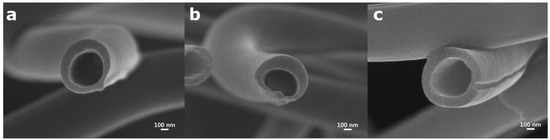
Figure 11.
Different morphologies of hollow carbon nanofibers fabricated via different nozzle setups, (a) normal nozzle (the core and shell nozzle outlets meet at the same position); (b) middle nozzle (the core nozzle outlet length is shorter than that of the shell nozzle); and (c) core-cut nozzle (the core nozzle outlet is removed). Reprinted from ref. [55].
5.7. Polarity
Electrospinning with a high voltage electrode applied to the nozzle produces a more intense and concentrated electric field on the nozzle. When the jet travels the distance between the high-charged needle and the collector, it encounters a decreasing electrostatic force. This promotes chaotic whipping instability, which results in a large area of fiber deposition—on the other hand, increasing the collector voltage results in a more intense electric field near the collector, strengthening the jet movement toward the collector. This effectively eliminates the whipping movement [8].
In this regard, not only can charge polarity affect the electrospinning process and its stability, but it can also be used to tailor the morphology of fibers and some of their properties, such as wettability, mechanical properties, and the efficiency of surface modification [56]. In [56], the effect of the electrospinning nozzle’s charge polarity on the polycaprolactone/chitosan (PCL/CHT) mixtures’ morphologies were studied, particularly the impact of surface modification with chondroitin sulphate (CS). It was shown that charge polarity has an effect on the morphology of PCL/CHT fibers and thus on certain properties, such as mechanical properties, wettability, and surface modification efficiency (see Figure 12. Polarity has a more substantial effect at higher chitosan concentrations. Both the crystallinity and melting temperatures of PCL are evidently lower at negative polarity in samples 25+ and 25-. Additionally, increasing the external positive potential increases the interactions between chitosan cations, resulting in a smaller average fiber diameter and thus a higher modulus.
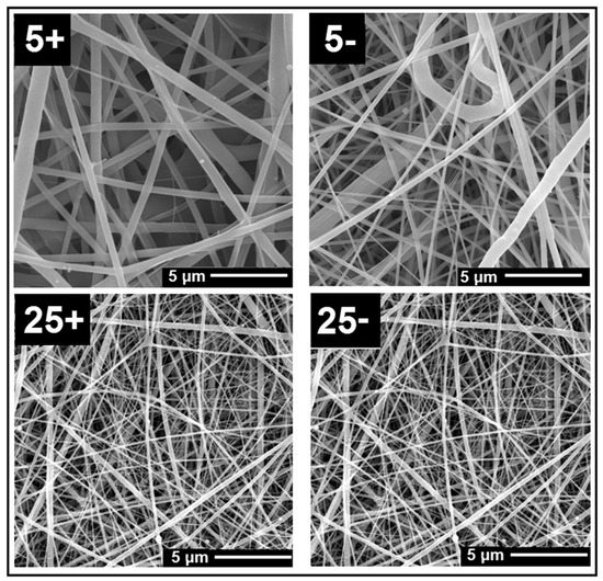
Figure 12.
FESEM images of PCL/CHT samples formed on the spinning nozzle with negative and positive charge polarity. Reprinted with permission from ref. [56].
5.8. Humidity
The morphology of electrospun fibers is affected by ambient humidity, i.e., the jet solution and moisture interaction. Humidity has an effect on fiber diameter by altering the rate of solvent evaporation; with increasing humidity, the average diameter of nanofibers decreases. Beaded fibers begin to form in environments with high relative humidity. On the other hand, at relatively low humidity levels, the solvent evaporation rate may be increased due to the pressure difference between the vapor and ambient air inside the electrospinning chamber. As a result, fibers solidify, resulting in coarser fibers than fibers generated at relatively higher humidity levels [57].
In [58], the relative standard deviation (RSD) values calculated from SEM images demonstrate how humidity can affect the morphological homogeneity or heterogeneity of electrospun and nanofiber diameters. At 30% relative humidity, electrospun was found to have the optimal relative humidity (RH). It can be confirmed from Figure 13 that higher relative humidities could result in non-uniform structures as the beads-on-string and individual beads start to appear.
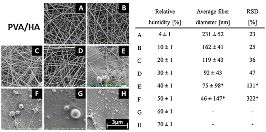
Figure 13.
The FESEM images of the PVA/HA electrospun fibers, the average fiber diameter, and the fiber diameter relative standard deviation (RSD) are shown in relation to the electrospinning process’s relative humidity conditions. In addition, * indicates nanofibers with a bead morphology at higher RH rates. Reprinted with permission from ref. [58].
Humidity also has an effect on the surface structure, causing the formation of porous fibers under conditions of rapid evaporation caused by low humidity. This could be attributed to the fact that evaporation removes heat from the jet surface, lowering the surface temperature to a point where tiny ice crystals can form on the filament surface. These microscopic ice crystals are retained until the deposited fibers on the collector’s surface exchange heat with the ambient air and reach the ambient temperature [58].
5.9. Temperature
Temperature is assumed to be inextricably linked to polymer properties such as crystallinity and molecular chain orientations. According to Yang et al., as the ambient temperature increases, the surface tension and viscosity of the electrospinning solution decrease. Increased temperature, on the other hand, results in rapid evaporation of the solvent, which can disrupt the electrospinning process. As a result, a balanced temperature point must be established in order to achieve the desired fiber quality [57,59].
In [60], as shown in Figure 14, the FESEM images of electrospun fibers at temperatures of 20 C, 22 C, 27 C, and 32 C for the Chitosan solutions can be seen. Surprisingly, as the solution temperature increased, the morphology of the fibers changed from beads-on-string to uniform structure. This finding could be extremely beneficial for the formation of uniform electrospun fibers, and it was shown that the morphologies were consistent with the electrospinning of nylon 6, chitosan/polyethylene oxide, and chitosan/poly(acrylamide).
Figure 14.
FESEM images of electrospun Chitosan solution at a concentration of 80 mg/mL in the solvents TFA/DCM (70/30 v/v) at four different ambient temperatures: (a) 20 C; (b) 22 C; (c) 27 C; and (d) 32 C. Reprinted from ref. [60].
6. Common Polymers in Electrospinning
Natural, synthetic, or copolymer polymers can be used in electrospinning, depending on the manufacturer’s requirements and material availability. Collagen, chitosan, and fibrinogen are all examples of natural polymers [9]. Due to their immunogenicity and biocompatibility, natural polymers have advantages over synthetic polymers. Collagen and gelatin are natural polymers that can be used as solutions in the electrospinning process [61]. Natural fibers may not suffice in situations where synthetic fibers are readily available. Polyvinyl alcohol (PVA), polyvinylpyrrolidone (PVP), polylactide (PLA), polyglycolide (PGA), poly-D-lactide (PLDA), and polylactide-co-glycolide are a few examples of synthetic polymers (PLGA) [35]. Copolymers can be created by combining natural or synthetic fibers or by combining several synthetic fibers [62]. The objective is to develop polymers resistant to a variety of constraints, including heat and degradation. Copolymers are frequently created to overcome the inherent limitations of a particular natural or synthetic polymer [63]. For instance, poly (glycolide) can be added to poly (ethylene-co-vinyl alcohol) to reduce its stiffness or rigidity (PEVA) [64]. The majority of copolymers exhibit a variety of properties that manufacturers require in order to develop suitable nanofibers.
7. Applications of Nano-Fiber Mats via Electrospinning
When it comes to biomedical applications, mimicking the native extracellular matrix (ECM) as close to its form and function is essential. Native ECM can be seen as a 3D network of a fibrous structure in terms of architecture. Due to their unique ability to summarize the composition, length, and architecture typical of the indigenous ECM, electrospun nanofibers were extensively explored to mimic ECM function as a scaffolding material class. An extensive array of synthetic and natural polymers can be electrolyzed into nanofibers from the perspective of composition, and nanofibers can be easily integrated into them [65].
Electrospinning has been shown to be the most cost-effective method of manufacturing various medical fibers such as medical implants, scaffolds, and wound dressings for artificial human tissues. Scaffolds behave similarly to the extracellular matrix that exists in natural tissues [66,67,68,69]. Biodegradable fibers serve as an extracellular matrix and can be coated with collages to aid in cell attachment. Additionally, the application of electrospun fibers extends to catalysts and enzymes, serving as a surface on which enzymes can be immobilized. The enzyme may be critical in the decomposition of toxic chemicals found in the environment [70].
The biomedical application of nanofibers entails tissue engineering, in which an electrospun scaffold is penetrated by cells that treat or replace biological targets [71]. Additionally, wound dressings made of nanofibers excel at isolating the wound from microbial infections [72]. Electrospinning plays a critical role in developing medical textile materials and a variety of fibrous treatment delivery systems such as transdermal patches and implants. Electrospinning has the potential to enable the pharmaceutical industry to establish a continuous manufacturing system. Electrospinning is a method for converting synthesized liquids into tablets [73].
In summary, the main focuses of electrospun nanofibers for biomedical applications can be sought on the repair or regeneration of various types of tissues [65], cell migration and stem cell differentiation [74], wound healing [75], cancer diagnosis and treatment [76], and release control and drug delivery applications [53].
The highly porous structure formed by electrospun nanofibers and the resulting random entanglement of nanofibers within non-woven mat structures significantly facilitates the mass transport of gaseous and liquid samples. A gas stream or solution can flow freely through a non-woven mat of electrospun nanofibers. Therefore, nanofiber-based mats, particularly those with controlled alignment and surface functionalization, have been investigated extensively as advanced filters for removing pollutants such as Particulate Matter (PMs), organic molecules, and toxic ions from polluted air and wastewater. Due to their high adsorption capacity, electrospun nanofibers have received considerable attention in the decontamination of hazardous chemicals [77]. Due to the strong binding between the functional groups and metal ions and the large surface-to-volume ratio of a non-woven mat, nanofibers with appropriate functional groups can efficiently scavenge precious metal ions from the surface of the solution phase.
Furthermore, the high absorption efficiency of fibrous webs is due to their high porosity, which traps sound waves within the cavity, and their ability to convert acoustic energy to other forms of energy (such as heat) via fiber vibration has been reported in the literature for sound absorption applications. The sound absorption performance can be significantly improved by adding a thin layer or multiple layers of electrospun nanofibers to traditional non-woven fabrics [78].
Additionally, it has been demonstrated that the composite nanofiber web can be used as a portable tool for fingerprint examination on a variety of substrates [79]. Moreover, in micro-reactors, chemical reactions are carried out on an infinitesimal scale, where electrospun nanofiber-based microreactors could facilitate zeptomole-level chemical reactions [80]. In textile manufacturing, nanofibers enable the development of seamless non-woven garments with a range of functions, including environmental, flame, and chemical protection. Electrospinning enables the combination of multiple coatings and fibers to create three-dimensional shapes, such as clothing composed of numerous polymer layers [81].
Electrospinning is used to create fibers for energy conversion and storage systems (see Figure 15. Fibers not only provide adequate storage space but also play a critical role in converting stored energy to electrical currents. Electrospun nanofibers have been implemented in various energy devices, such as rechargeable batteries, supercapacitors, solar cells, fuel cells, and piezoelectric power generators. Due to the high surface-to-volume ratio and a relatively defect-free molecular structure of homogenous nanofiber mats, their application extends to various electronic devices such as sensors, electrochromic devices, field–effect transistors, light-emitting diodes, P-N diode, photoconductors, field-emission cells, triboelectric power generators, thermoelectric power generators, photo-coupling devices, and electro-active actuators [65].
Figure 15.
An example of uniform ultra-fine nano-fibers (diameter <∼ 150 nm) resulting from polymerized electro-spun tailored for Li-ion cathode materials suitable for the fabrication of ultra-high capacity Li-ion batteries. Reprinted from ref. [17].
Electrospinning has a number of advantages, including its ability to operate at a range of temperatures, a short production cycle, and low pressure. Additionally, hydrothermally synthesized nanofibers have a lower aspect ratio, which is critical for energy transfer [82]. In other words, electrospun fibers are likely to be more efficient at transferring energy than other methods, such as electrospun nanowovens [83].
However, electrospinning has some limitations, including difficulty producing inorganic nanofibers and a limited number or variety of polymers used in the process. Due to the scarcity of polymers, manufacturers are forced to use materials that may not achieve the desired energy capacities [84]. Additionally, the performance of nanofibers synthesized from inorganic materials is likely to degrade following calcination. Furthermore, manufacturers remain silent about the aging process that degrades the efficiency of many batteries. The aging process depletes the energy capacity of various cells and degrades lithium-ion battery performance [85]. There is ongoing research to ascertain the cause of aging and to develop appropriate interventions [86].
Finally, in summary, in Figure 16, various applications of electrospun nanofiber mats could be categorized in energy conversion and storage, electronic, biomedical, environment and sustainability, and other applications.
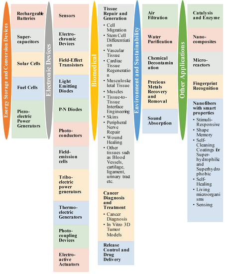
Figure 16.
Various applications of electro-spun nanaofibers.
8. Conclusions, Challenges, and Future Perspectives
Electrospinning has several advantages, including efficiency, simplicity, inexpensive setup, and controllability of the procedure to control many factors, such as the fiber diameter, orientation, layers, and composition. Various variables can influence nanofiber mats’ fabrication and lead to different morphologies, such as uniform or entangled patterns with different cross-sectional structures, individual beads, beads-on-string, etc. On the other hand, electrospinning has a number of limitations, including difficulties in preparing inorganic nanofibers and a limited quantity or variety of polymers used in the process. Additionally, the performance of nanofibers synthesized from inorganic materials is likely to degrade following calcination.
In this study, the effective parameters that could affect nanofibers’ fabrication and how these parameters could be engineered to result in more homogenous and uniform solution-based electrospun nanofiber morphologies were studied. Every effective parameter was studied individually, independent from other effective parameters, to differentiate them from the morphology optimization standpoint of solution-based electrospun nanofibers. One should be concerned about the concentration and viscosity of the solution, solvent properties, voltage and electric field, flow rate, collecting distance, nozzle geometry, solution polarity, and the humidity and temperature of the ambient air before implementation of the electrospinning process for various applications.
Electrospinning, nowadays, is applicable in numerous fields such as energy storage and conversion devices, electronic devices, biomedical applications such as tissue repair and generation, cancer diagnosis and treatment, release control and drug delivery, environment, and sustainability areas such as air filtration, water purification, and many other domains.
Author Contributions
Conceptualization, A.A.; methdology, A.A.; validation, A.A., A.S., N.A. and M.A.; formal analysis, A.A.; investigation, A.A.; resources, A.A., and A.S.; writing—original draft preparation, A.A.; writing—review and editing, A.A. and A.S.; visualization, A.A.; supervision, A.A., N.A. and M.A. All authors have read and agreed to the published version of the manuscript.
Funding
This research received no external funding.
Institutional Review Board Statement
Not applicable.
Informed Consent Statement
Not applicable.
Data Availability Statement
The study did not report any data.
Conflicts of Interest
The authors declare no conflict of interest.
References
- Bora, N.S.; Mazumder, B.; Pathak, M.P.; Joshi, K.; Chattopadhyay, P. Nanotechnology in Preventive and Emergency Healthcare. In Nanotechnology: Therapeutic, Nutraceutical, and Cosmetic Advances; CRC Press: Boca Raton, FL, USA, 2019; p. 221. [Google Scholar]
- Subbiah, T.; Bhat, G.; Tock, R.; Parameswaran, S.; Ramkumar, S. Electrospinning of nanofibers. J. Appl. Polym. Sci. 2005, 96, 557–569. [Google Scholar] [CrossRef]
- Anton, F. Process and Apparatus for Preparing Artificial Threads. U.S. Patent 1,975,504, 2 October 1934. [Google Scholar]
- D’Avino, G.; Muccioli, L.; Castet, F.; Poelking, C.; Andrienko, D.; Soos, Z.G.; Cornil, J.; Beljonne, D. Electrostatic phenomena in organic semiconductors: Fundamentals and implications for photovoltaics. J. Phys. Condens. Matter 2016, 28, 433002. [Google Scholar] [CrossRef]
- Xiao, K.; Zhou, Y.; Kong, X.Y.; Xie, G.; Li, P.; Zhang, Z.; Wen, L.; Jiang, L. Electrostatic-charge-and electric-field-induced smart gating for water transportation. ACS Nano 2016, 10, 9703–9709. [Google Scholar] [CrossRef]
- Hughes, J.; Schaub, H. Effects of charged dielectrics on electrostatic force and torque. In International Workshop on Spacecraft Formation Flying; International Astronautical Federation: Boulder, CO, USA, 2017. [Google Scholar]
- Bhardwaj, N.; Kundu, S.C. Electrospinning: A fascinating fiber fabrication technique. Biotechnol. Adv. 2010, 28, 325–347. [Google Scholar] [CrossRef]
- Lin, T.; Fang, J. Fundamentals of Electrospinning and Electrospun Nanofibers; DEStech Publications: Lancaster, PA, USA, 2017. [Google Scholar]
- Angammana, C.J.; Jayaram, S.H. Fundamentals of electrospinning and processing technologies. Part. Sci. Technol. 2016, 34, 72–82. [Google Scholar] [CrossRef]
- Li, D.; Xia, Y. Electrospinning of nanofibers: Reinventing the wheel? Adv. Mater. 2004, 16, 1151–1170. [Google Scholar] [CrossRef]
- Greiner, A.; Wendorff, J.H. Electrospinning: A fascinating method for the preparation of ultrathin fibers. Angew. Chem. Int. Ed. 2007, 46, 5670–5703. [Google Scholar] [CrossRef]
- Luo, C.; Stoyanov, S.D.; Stride, E.; Pelan, E.; Edirisinghe, M. Electrospinning versus fibre production methods: From specifics to technological convergence. Chem. Soc. Rev. 2012, 41, 4708–4735. [Google Scholar] [CrossRef]
- Sill, T.J.; von Recum, H.A. Electrospinning: Applications in drug delivery and tissue engineering. Biomaterials 2008, 29, 1989–2006. [Google Scholar] [CrossRef] [PubMed]
- Li, W.; Tuan, R.S. Fabrication and application of nanofibrous scaffolds in tissue engineering. Curr. Protoc. Cell Biol. 2009, 42, 25.2.1–25.2.12. [Google Scholar] [CrossRef] [PubMed]
- Brown, T.D.; Dalton, P.D.; Hutmacher, D.W. Melt electrospinning today: An opportune time for an emerging polymer process. Prog. Polym. Sci. 2016, 56, 116–166. [Google Scholar] [CrossRef]
- Yousefzadeh, M. Modeling and simulation of the electrospinning process. In Electrospun Nanofibers; Elsevier: Amsterdam, The Netherlands, 2017; pp. 277–301. [Google Scholar]
- Ahmadian, A. Design and Fabrication of High Capacity Lithium-Ion Batteries Using Electro-Spun Graphene Modified Vanadium Pentoxide Cathodes. Master’s Thesis, Purdue University Graduate School, West Lafayette, IN, USA, 2019. [Google Scholar]
- Shuakat, M.N.; Lin, T. Recent developments in electrospinning of nanofiber yarns. J. Nanosci. Nanotechnol. 2014, 14, 1389–1408. [Google Scholar] [CrossRef] [PubMed]
- Démuth, B.; Farkas, A.; Pataki, H.; Balogh, A.; Szabó, B.; Borbás, E.; Sóti, P.L.; Vigh, T.; Kiserdei, É.; Farkas, B. Detailed stability investigation of amorphous solid dispersions prepared by single-needle and high speed electrospinning. Int. J. Pharm. 2016, 498, 234–244. [Google Scholar] [CrossRef]
- Susanto, H.; Samsudin, A.; Faz, M.; Rani, M. Impact of post-treatment on the characteristics of electrospun poly (vinyl alcohol)/chitosan nanofibers. In AIP Conference Proceedings; AIP Publishing: Melville, NY, USA, 2016; Volume 1725, p. 020087. [Google Scholar]
- Zhou, F.; Gong, R.; Porat, I. Mass production of nanofibre assemblies by electrostatic spinning. Polym. Int. 2009, 58, 331–342. [Google Scholar] [CrossRef]
- Wang, X.; Niu, H.; Lin, T.; Wang, X. Needleless electrospinning of nanofibers with a conical wire coil. Polym. Eng. Sci. 2009, 49, 1582–1586. [Google Scholar] [CrossRef] [Green Version]
- King, M.W.; Gupta, B.S.; Guidoin, R. Biotextiles as Medical Implants; Elsevier: Amsterdam, The Netherlands, 2013. [Google Scholar]
- Hohman, M.M.; Shin, M.; Rutledge, G.; Brenner, M.P. Electrospinning and electrically forced jets. I. Stability theory. Phys. Fluids 2001, 13, 2201–2220. [Google Scholar] [CrossRef] [Green Version]
- Cosio, M.S.; Benedetti, S.; Scampicchio, M.; Mannino, S. Electroanalysis in food process control. In Agricultural and Food Electroanalysis; John Wiley & Sons, Ltd.: Chichester, UK, 2015; pp. 421–441. [Google Scholar]
- Guo, H.F.; Xu, B.G. Numerical study of Taylor cone dynamics in electrospinning of nanofibers. In Key Engineering Materials; Trans Tech Publications Ltd.: Freienbach, Switzerland, 2017; Volume 730, pp. 510–515. [Google Scholar]
- Reneker, D.H.; Yarin, A.L. Electrospinning jets and polymer nanofibers. Polymer 2008, 49, 2387–2425. [Google Scholar] [CrossRef] [Green Version]
- Guerrero, J.; Rivero, J.; Gundabala, V.R.; Perez-Saborid, M.; Fernandez-Nieves, A. Whipping of electrified liquid jets. Proc. Natl. Acad. Sci. USA 2014, 111, 13763–13767. [Google Scholar] [CrossRef] [Green Version]
- Huang, Z.M.; Zhang, Y.Z.; Kotaki, M.; Ramakrishna, S. A review on polymer nanofibers by electrospinning and their applications in nanocomposites. Compos. Sci. Technol. 2003, 63, 2223–2253. [Google Scholar] [CrossRef]
- Jirsak, O.; Sanetrnik, F.; Lukas, D.; Kotek, V.; Martinova, L.; Chaloupek, J. Method of Nanofibres Production from a Polymer Solution Using Electrostatic Spinning and a Device for Carrying Out the Method. U.S. Patent 7,585,437, 8 September 2009. [Google Scholar]
- Luzio, A.; Canesi, E.; Bertarelli, C.; Caironi, M. Electrospun polymer fibers for electronic applications. Materials 2014, 7, 906–947. [Google Scholar] [CrossRef]
- Khajavi, R.; Abbasipour, M. Controlling nanofiber morphology by the electrospinning process. In Electrospun Nanofibers; Elsevier: Amsterdam, The Netherlands, 2017; pp. 109–123. [Google Scholar]
- Leach, M.K.; Feng, Z.Q.; Tuck, S.J.; Corey, J.M. Electrospinning fundamentals: Optimizing solution and apparatus parameters. JoVE (J. Vis. Exp.) 2011, 47, e2494. [Google Scholar] [CrossRef] [PubMed]
- Erdem, R.; Usta, I.; Akalin, M.; Atak, O.; Yuksek, M.; Pars, A. The impact of solvent type and mixing ratios of solvents on the properties of polyurethane based electrospun nanofibers. Appl. Surf. Sci. 2015, 334, 227–230. [Google Scholar] [CrossRef]
- Lin, T.; Wang, H.; Wang, H.; Wang, X. Effects of polymer concentration and cationic surfactant on the morphology of electrospun polyacrylonitrile nanofibres. J. Mater. Sci. Technol. 2005, 21, 1–4. [Google Scholar]
- Bercea, M.; Morariu, S.; Ioan, C.; Ioan, S.; Simionescu, B.C. Viscometric study of extremely dilute polyacrylonitrile solutions. Eur. Polym. J. 1999, 35, 2019–2024. [Google Scholar] [CrossRef]
- Moriya, A.; Shen, P.; Ohmukai, Y.; Maruyama, T.; Matsuyama, H. Reduction of fouling on poly (lactic acid) hollow fiber membranes by blending with poly (lactic acid)–polyethylene glycol–poly (lactic acid) triblock copolymers. J. Membr. Sci. 2012, 415, 712–717. [Google Scholar] [CrossRef]
- Estanqueiro, M.; Vasconcelos, H.; Lobo, J.M.S.; Amaral, H. Delivering miRNA modulators for cancer treatment. In Drug Targeting and Stimuli Sensitive Drug Delivery Systems; Elsevier: Amsterdam, The Netherlands, 2018; pp. 517–565. [Google Scholar]
- Hsu, C.M.; Shivkumar, S. Nano-sized beads and porous fiber constructs of poly (ϵ-caprolactone) produced by electrospinning. J. Mater. Sci. 2004, 39, 3003–3013. [Google Scholar] [CrossRef]
- Wu, Y.K.; Wang, L.; Fan, J.; Shou, W.; Zhou, B.M.; Liu, Y. Multi-jet electrospinning with auxiliary electrode: The influence of solution properties. Polymers 2018, 10, 572. [Google Scholar] [CrossRef] [PubMed] [Green Version]
- Lasprilla-Botero, J.; Álvarez-Láinez, M.; Lagaron, J. The influence of electrospinning parameters and solvent selection on the morphology and diameter of polyimide nanofibers. Mater. Today Commun. 2018, 14, 1–9. [Google Scholar] [CrossRef]
- Li, X.; Lin, J.; Zeng, Y. Electric field distribution and initial jet motion induced by spinneret configuration for molecular orientation in electrospun fibers. Eur. Polym. J. 2018, 98, 330–336. [Google Scholar] [CrossRef]
- Meechaisue, C.; Dubin, R.; Supaphol, P.; Hoven, V.P.; Kohn, J. Electrospun mat of tyrosine-derived polycarbonate fibers for potential use as tissue scaffolding material. J. Biomater. Sci. Polym. Ed. 2006, 17, 1039–1056. [Google Scholar] [CrossRef]
- Balogh, A.; Cselkó, R.; Démuth, B.; Verreck, G.; Mensch, J.; Marosi, G.; Nagy, Z.K. Alternating current electrospinning for preparation of fibrous drug delivery systems. Int. J. Pharm. 2015, 495, 75–80. [Google Scholar] [CrossRef]
- Balogh, A.; Farkas, B.; Pálvölgyi, Á.; Domokos, A.; Démuth, B.; Marosi, G.; Nagy, Z.K. Novel alternating current electrospinning of hydroxypropylmethylcellulose acetate succinate (HPMCAS) nanofibers for dissolution enhancement: The importance of solution conductivity. J. Pharm. Sci. 2017, 106, 1634–1643. [Google Scholar] [CrossRef]
- Pokorny, P.; Kostakova, E.; Sanetrnik, F.; Mikes, P.; Chvojka, J.; Kalous, T.; Bilek, M.; Pejchar, K.; Valtera, J.; Lukas, D. Effective AC needleless and collectorless electrospinning for yarn production. Phys. Chem. Chem. Phys. 2014, 16, 26816–26822. [Google Scholar] [CrossRef]
- Kessick, R.; Fenn, J.; Tepper, G. The use of AC potentials in electrospraying and electrospinning processes. Polymer 2004, 45, 2981–2984. [Google Scholar] [CrossRef]
- Mirek, A.; Korycka, P.; Grzeczkowicz, M.; Lewińska, D. Polymer fibers electrospun using pulsed voltage. Mater. Des. 2019, 183, 108106. [Google Scholar] [CrossRef]
- Theron, S.; Zussman, E.; Yarin, A. Experimental investigation of the governing parameters in the electrospinning of polymer solutions. Polymer 2004, 45, 2017–2030. [Google Scholar] [CrossRef]
- Srivastava, R. Electrospinning of patterned and 3D nanofibers. In Electrospun Nanofibers; Elsevier: Amsterdam, The Netherlands, 2017; pp. 399–447. [Google Scholar]
- Wang, L.; Ryan, A. Introduction to electrospinning. In Electrospinning for Tissue Regeneration; Elsevier: Amsterdam, The Netherlands, 2011; pp. 3–33. [Google Scholar]
- Arrieta, M.P.; Leonés Gil, A.; Yusef, M.; Kenny, J.M.; Peponi, L. Electrospinning of PCL-based blends: Processing optimization for their scalable production. Materials 2020, 13, 3853. [Google Scholar] [CrossRef]
- Pant, B.; Park, M.; Park, S.J. Drug delivery applications of core-sheath nanofibers prepared by coaxial electrospinning: A review. Pharmaceutics 2019, 11, 305. [Google Scholar] [CrossRef] [PubMed] [Green Version]
- Lubasova, D.; Netravali, A.N. A novel method for electrospinning nanofibrous 3D structures. Fibers 2020, 8, 27. [Google Scholar] [CrossRef]
- Lee, B.S.; Jeon, S.Y.; Park, H.; Lee, G.; Yang, H.S.; Yu, W.R. New electrospinning nozzle to reduce jet instability and its application to manufacture of multi-layered nanofibers. Sci. Rep. 2014, 4, 6758. [Google Scholar] [CrossRef]
- Urbanek, O.; Sajkiewicz, P.; Pierini, F. The effect of polarity in the electrospinning process on PCL/chitosan nanofibres’ structure, properties and efficiency of surface modification. Polymer 2017, 124, 168–175. [Google Scholar] [CrossRef]
- De Vrieze, S.; Van Camp, T.; Nelvig, A.; Hagström, B.; Westbroek, P.; De Clerck, K. The effect of temperature and humidity on electrospinning. J. Mater. Sci. 2009, 44, 1357–1362. [Google Scholar] [CrossRef]
- Pelipenko, J.; Kristl, J.; Janković, B.; Baumgartner, S.; Kocbek, P. The impact of relative humidity during electrospinning on the morphology and mechanical properties of nanofibers. Int. J. Pharm. 2013, 456, 125–134. [Google Scholar] [CrossRef] [PubMed]
- Yang, G.Z.; Li, H.P.; Yang, J.H.; Wan, J.; Yu, D.G. Influence of working temperature on the formation of electrospun polymer nanofibers. Nanoscale Res. Lett. 2017, 12, 55. [Google Scholar] [CrossRef] [Green Version]
- Van-Pham, D.T.; Quyen, T.T.B.; Van Toan, P.; Nguyen, C.N.; Ho, M.H.; Thien, D.V.H. Temperature effects on electrospun chitosan nanofibers. Green Process. Synth. 2020, 9, 488–495. [Google Scholar] [CrossRef]
- Sell, S.A.; Wolfe, P.S.; Garg, K.; McCool, J.M.; Rodriguez, I.A.; Bowlin, G.L. The use of natural polymers in tissue engineering: A focus on electrospun extracellular matrix analogues. Polymers 2010, 2, 522–553. [Google Scholar] [CrossRef]
- Gupta, P.; Elkins, C.; Long, T.E.; Wilkes, G.L. Electrospinning of linear homopolymers of poly (methyl methacrylate): Exploring relationships between fiber formation, viscosity, molecular weight and concentration in a good solvent. Polymer 2005, 46, 4799–4810. [Google Scholar] [CrossRef]
- Shenoy, S.L.; Bates, W.D.; Frisch, H.L.; Wnek, G.E. Role of chain entanglements on fiber formation during electrospinning of polymer solutions: Good solvent, non-specific polymer–polymer interaction limit. Polymer 2005, 46, 3372–3384. [Google Scholar] [CrossRef]
- Shenoy, S.L.; Bates, W.D.; Wnek, G. Correlations between electrospinnability and physical gelation. Polymer 2005, 46, 8990–9004. [Google Scholar] [CrossRef]
- Xue, J.; Wu, T.; Dai, Y.; Xia, Y. Electrospinning and electrospun nanofibers: Methods, materials, and applications. Chem. Rev. 2019, 119, 5298–5415. [Google Scholar] [CrossRef]
- Poudel, B.K.; Doh, K.O.; Byeon, J.H. Green and continuous route to assemble lateral nanodimensional graphitic oxide composites without process interruption. Green Chem. 2018, 20, 2984–2989. [Google Scholar] [CrossRef]
- Akbar, M.; Mortazavi Ashkezari, S.M.J.; Hasani Bidgoli, J.; Ahmadian, A.; Sadeghi, M.J.; Ahmadian, A.; Farahmand, F.; Sarkar, S. Robotic Guide for Brain Biopsy. U.S. Patent 10,555,784, 11 February 2020. [Google Scholar]
- Ahmadian, A.; Hasani Bidgoli, J.; Sadeghi, M.J.; Ahmadian, A.; Farahmand, F.; Sarkar, S. Device for Brain Biopsy. U.S. Patent No. 10,631,947, 28 April 2020. [Google Scholar]
- Ahmadian, A. A Review on Recent Selective Laser Sintering Printing of Medicines; Technical Report; EasyChair: Manchester, UK, 2021. [Google Scholar]
- Korkmaz, S.; Tezel, F.M.; Kariper, I. Synthesis and Characterization of GO/V2O5 Thin Film Supercapacitor. Synth. Met. 2018, 242, 37–48. [Google Scholar] [CrossRef]
- Daemi, N.; Ahmadian, A.; Mirbagheri, A.; Ahmadian, A.; Saberi, H.; Amidi, F.; Alirezaie, J. Planning screw insertion trajectory in lumbar spinal fusion using pre-operative CT images. In Proceedings of the 2015 37th Annual International Conference of the IEEE Engineering in Medicine and Biology Society (EMBC), Milan, Italy, 25–29 August 2015; pp. 3639–3642. [Google Scholar]
- Monyoncho, E.A.; Bissessur, R.; Dahn, D.C.; Trenton, V. Intercalation of poly [oligo (ethylene glycol) oxalate] into vanadium pentoxide xerogel. In Alkali-Ion Batteries; IntechOpen: London, UK, 2016; pp. 93–110. [Google Scholar]
- Reina, G.; González-Domínguez, J.M.; Criado, A.; Vázquez, E.; Bianco, A.; Prato, M. Promises, facts and challenges for graphene in biomedical applications. Chem. Soc. Rev. 2017, 46, 4400–4416. [Google Scholar] [CrossRef] [PubMed] [Green Version]
- Mayor, R.; Etienne-Manneville, S. The front and rear of collective cell migration. Nat. Rev. Mol. Cell Biol. 2016, 17, 97. [Google Scholar] [CrossRef] [PubMed] [Green Version]
- Ren, X.; Han, Y.; Wang, J.; Jiang, Y.; Yi, Z.; Xu, H.; Ke, Q. An aligned porous electrospun fibrous membrane with controlled drug delivery—An efficient strategy to accelerate diabetic wound healing with improved angiogenesis. Acta Biomater. 2018, 70, 140–153. [Google Scholar] [CrossRef]
- Chen, S.; Boda, S.K.; Batra, S.K.; Li, X.; Xie, J. Emerging roles of electrospun nanofibers in cancer research. Adv. Healthc. Mater. 2018, 7, 1701024. [Google Scholar] [CrossRef]
- Ahmed, F.E.; Lalia, B.S.; Hashaikeh, R. A review on electrospinning for membrane fabrication: Challenges and applications. Desalination 2015, 356, 15–30. [Google Scholar] [CrossRef]
- Rabbi, A.; Bahrambeygi, H.; Shoushtari, A.M.; Nasouri, K. Incorporation of nanofiber layers in non-woven materials for improving their acoustic properties. J. Eng. Fibers Fabr. 2013, 8, 155892501300800412. [Google Scholar]
- Yang, S.; Wang, C.F.; Chen, S. A Release-Induced Response for the Rapid Recognition of Latent Fingerprints and Formation of Inkjet-Printed Patterns. Angew. Chem. Int. Ed. 2011, 50, 3706–3709. [Google Scholar] [CrossRef] [PubMed]
- Anzenbacher, P., Jr.; Palacios, M.A. Polymer nanofibre junctions of attolitre volume serve as zeptomole-scale chemical reactors. Nat. Chem. 2009, 1, 80. [Google Scholar] [CrossRef]
- Barbosa, G.N.; Graeff, C.F.O.; Oliveira, H.P. Thermal annealing effects on vanadium pentoxide xerogel films. Eclet. Quim. 2005, 30, 7–15. [Google Scholar] [CrossRef]
- Huang, X.; Bahroloomi, D.; Xiao, X. A multilayer composite separator consisting of non-woven mats and ceramic particles for use in lithium ion batteries. J. Solid State Electrochem. 2014, 18, 133–139. [Google Scholar] [CrossRef]
- Kumar, R.; Sharma, R.K.; Singh, A.P. Grafted cellulose: A bio-based polymer for durable applications. Polym. Bull. 2018, 75, 2213–2242. [Google Scholar] [CrossRef]
- Shi, C.; Dai, J.; Li, C.; Shen, X.; Peng, L.; Zhang, P.; Wu, D.; Sun, D.; Zhao, J. A modified ceramic-coating separator with high-temperature stability for lithium-ion battery. Polymers 2017, 9, 159. [Google Scholar] [CrossRef] [PubMed]
- Ahmadian, A.; Shafiee, A.; Alidoost, M.; Akbari, A. Flexible Paper-Based Li-ion Batteries: A Review. World J. Eng. Technol. 2021, 9, 285. [Google Scholar] [CrossRef]
- Zhang, Q.; Tan, S.; Kong, X.; Xiao, Y.; Fu, L. Synthesis of sulfur encapsulated 3D graphene sponge driven by micro-pump and its application in Li–S battery. J. Mater. 2015, 1, 333–339. [Google Scholar] [CrossRef] [Green Version]
Publisher’s Note: MDPI stays neutral with regard to jurisdictional claims in published maps and institutional affiliations. |
© 2021 by the authors. Licensee MDPI, Basel, Switzerland. This article is an open access article distributed under the terms and conditions of the Creative Commons Attribution (CC BY) license (https://creativecommons.org/licenses/by/4.0/).