Abstract
This study proposes a receiving-end voltage compensation method employing a phase-specific reactive power control strategy with a neutral-point-clamped (NPC) inverter in a three-phase four-wire distribution system. The principle of the proposed receiving end voltage compensation method is explained. Further, the proposed control strategy can solve the problems of the three-phase, four-wire distribution system, which are an increase in the neutral-line current and the unbalanced voltage. Computer simulation is performed to confirm the validity of the proposed method. The simulation results indicate the receiving-end voltages can be compensated using the proposed method.
1. Introduction
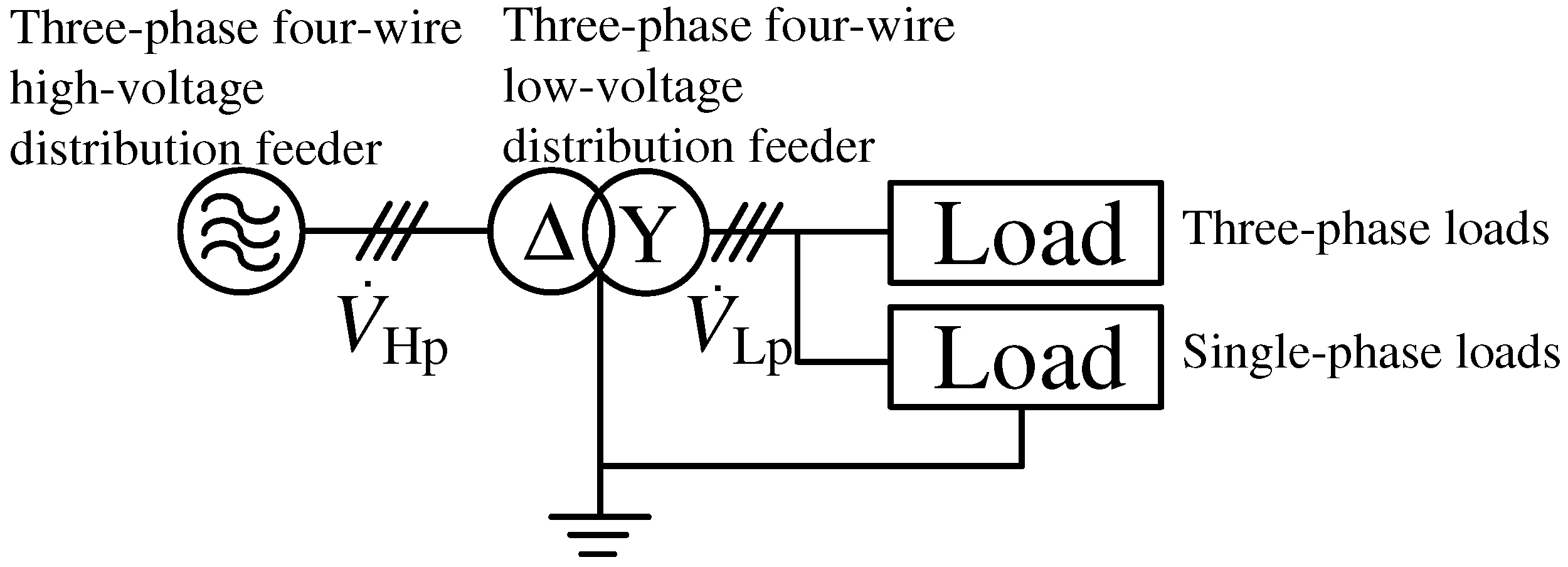
Low-voltage distribution systems differ among countries [1]. Both three- and single-phase three-wire low-voltage distribution feeders are used for consumer electronics and industrial loads in the United States, Canada, Taiwan, and Japan. In this case, both the single- and three-phase transformers are connected to a three-phase three-wire high-voltage distribution feeder. Certain Asian and European countries use three-phase four-wire distribution feeders (3P4WDFs). Figure 1 shows an example of a 3P4WDF, where both single- and three-phase loads are directly connected to the 3P4WDF.
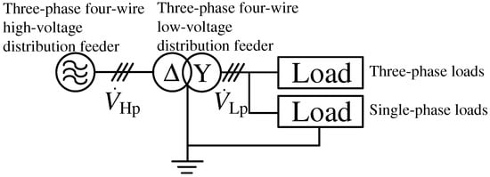
Figure 1.
Example of a 3P4WDF.
Today, consumer electronics often use diode rectifiers to transform AC into DC. When these single-phase loads are connected to a 3P4WDF, they lead to imbalanced and distorted currents in the feeders [2]. This imbalance and a distortion subsequently increase and distort the current in the neutral line. In particular, the efficiency of the distribution transformer is reduced by an increased and/or distorted neutral current. Therefore, the secondary-side voltages of the -Y-connected transformer , and are also unbalanced.
The per-phase base equivalent circuit for the -Y-connected transformer, which is illustrated in Figure 1, is explained. Let and be the primary- and secondary-sides phase voltage, be the per-phase based equivalent impedance of -Y-connected transformer, and a be the turns ratio of the transformer. is regulated by reactive power in each phase. Typically, the difference between and is expressed as
According to (1), is proportional to . Hence, it is evident that controlling the reactive power in each phase is essential for balancing the secondary-side voltages , , and .
Power quality compensation devices include static synchronous compensators (STATCOM) [3,4,5,6,7,8,9] and doubly fed induction generators (DFIG) [10,11], active power line conditioners (APLCs), etc. STATCOM is excellent at reactive power compensation and is the most effective solution [12]. In this paper, we consider an APLC, which is capable of providing comprehensive compensation through current control using a self-excited switch with power semiconductors.
To solve the problems of increased neutral-line current and unbalanced receiving-end voltages in 3P4WDF, an APLC has been proposed [13,14,15,16,17,18,19]. APLCs are active filters comprising a four-leg inverter and a DC capacitor. It can compensate for the unbalanced load currents by injecting compensation currents. However, the DC-capacitor voltage must exceed the feeder voltage. Thus, a high-withstand-voltage switching device and capacitor are required for APLCs.
Numerous papers have been published on the control strategies for APLCs based on the instantaneous active–reactive power theory [20,21,22]. In instantaneous active–reactive power theory, the active, reactive, and harmonic components are calculated on the coordinates. Recent studies have proposed new power conditioners for 3P4WDFs [23,24,25]. These studies used an instantaneous active–reactive power theory-based control algorithm with transforms to obtain balanced and sinusoidal source-side currents , , and while suppressing the neutral-line current. In a separate study, a new control algorithm was proposed for single-phase shunt active filters in 3P4WDFs [26]. This algorithm includes a constant DC-capacitor voltage control block in addition to the calculation block of the fundamental active–reactive currents. However, both these studies were limited to linear loads.
Three-phase four-wire distribution systems offer the advantage of concurrently accommodating both single- and three-phase loads. However, they present certain challenges, including increased neutral-line current and unbalanced receiving-end voltages. To address these issues, various control strategies for three-phase inverters have been extensively studied [27,28,29,30,31,32,33,34,35]. Specifically, studies have focused on control methodologies tailored for three-phase four-wire systems [27,28,29,30,31,32,33,34]. Certain proposed methods include the integration of uninterruptible power supply (UPS) and pulse width modulation (PWM) rectifier technologies into three-phase four-wire setups to enhance the control applications. Three-phase inverters have been utilized as compensators for power-quality compensation [27,28,29,30,31]. Although efforts have been made to control the phase-specific power at the source side, compensation for unbalanced receiving-end voltages remains unverified owing to the absence of significant voltage imbalances. Thus, this is merely a confirmation of the principle. Furthermore, the implementation of phase-specific unbalanced currents without suppressing the neutral-line current inadvertently increases the neutral-line current [27]. Techniques employing the thyristor switched capacitors (TSCs), passive filters, and distributed static synchronous compensator (D-STATCOM) aim to mitigate neutral-line currents, reduce voltage flickers, and select harmonics on the 3rd, 5th, and 7th [28]. However, these solutions often involve complex circuit configurations and are not universally effective in all harmonic compensation. In [29], switching from the grid-connected to islanded mode and from the islanded to grid-connected mode through active power compensation was explored. However, it did not adequately address the core challenges of neutral-line currents and unbalanced receiving-end voltages in three-phase four-wire systems.
APLCs in 3P4WDF using new control strategies have been reported [20,23,24,25]. In [20,23,24,25], balancing the source currents in a three-phase four-wire distribution system suppressed the neutral-line current. However, there exists a large neutral-line current under an asymmetrical grid fault [20]. In addition, although research has been carried out on stable operation under unbalanced load conditions and during system faults, there are no reports to date on research into the control of unbalanced voltages in a balanced manner [5,6]. To the best of our knowledge, a method for suppressing the neutral-line currents under unbalanced source current conditions has not yet been reported.
In most cases, there have been no reports on the compensation of unbalanced voltages, which is a major issue for 3P4WDF. According to IEC 60038, the highest voltage must not differ by more than +5% and the lowest voltage by more than –10% from the nominal voltage of the system [36]. Therefore, this study proposes a compensation method for the unbalanced receiving-end voltage deviating from the standards set by IEC while suppressing the total harmonic currents and neutral-line current using a phase-specific reactive power control strategy, as shown in Table 1.

Table 1.
Comparison with previous research on control methods.
This study proposes a receiving-end voltage compensation method using an NPC-inverter-based APLC in a 3P4WDF. The withstand voltage of the switching devices and capacitors can be reduced compared with the four-leg inverter-based APLC [18,19]. The proposed control strategy aims to compensate for unbalanced voltages at the receiving end while minimizing the current in the neutral line. The shortage of the reactive current component at the receiving end is calculated, and the active power is redistributed to the source side. The former compensates for the unbalanced receiving-end voltages, and the latter provides balanced three-phase source currents. Computer simulations are conducted to verify the effectiveness and feasibility of the proposed control strategy. The simulation results indicate that the strategy successfully compensates for the source currents and receiving-end voltages in each phase, while reducing the neutral-line current.
2. Three-Phase Four-Wire Distribution Systems Under Unbalanced Single-Phase Loads
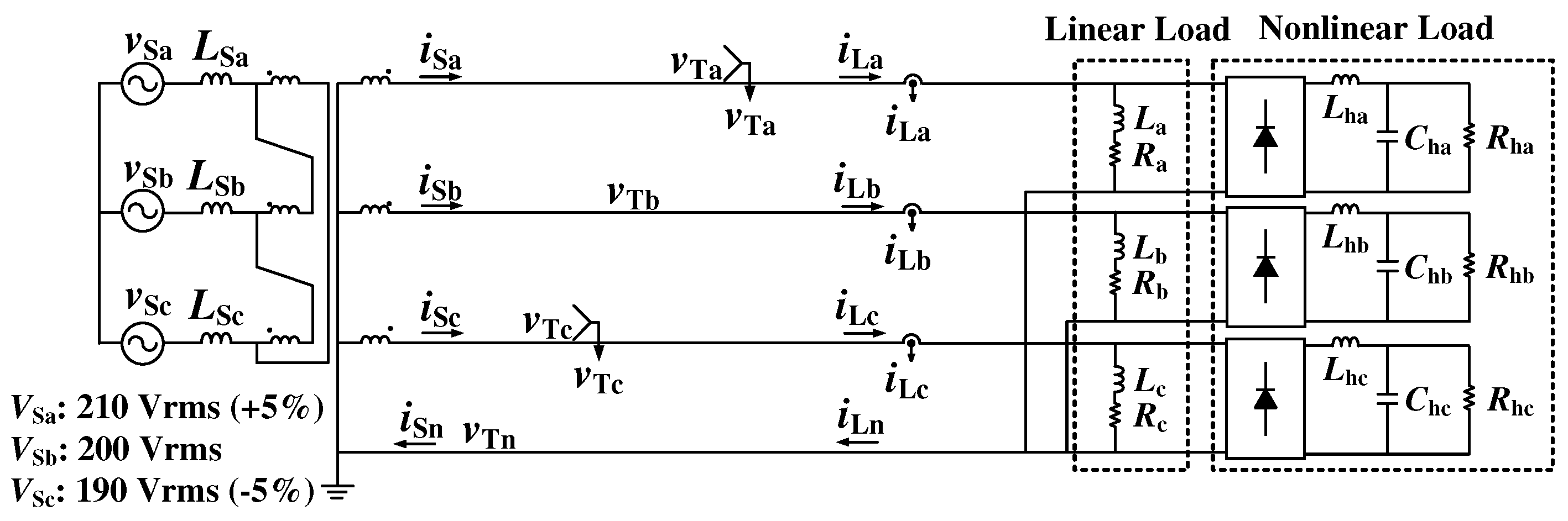
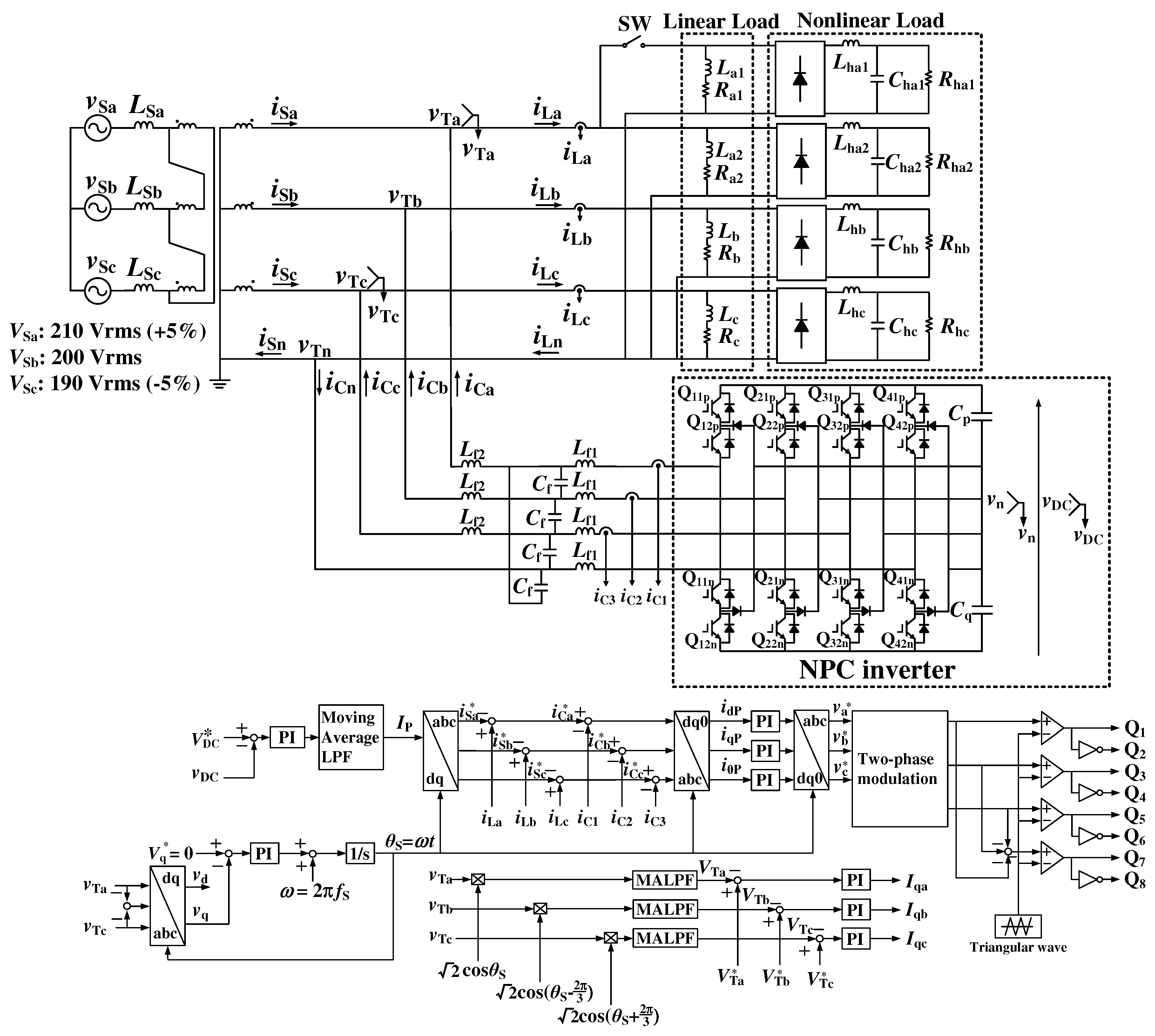
Figure 2 shows the power circuit diagram of 3P4WDF without an APLC. A -Y-connected transformer is used for low-voltage 3P4WDF. Single-phase linear and nonlinear loads are connected in 3P4WDF. The nonlinear load consists of a diode rectifier with capacitor input filter and resistor in this paper. Computer simulation is implemented using the PSIM circuit simulation software package to confirm the technical issues in 3P4WDF. In a 3P4WDF system, the root mean square (RMS) value of the line-to-line voltage is typically 380 or 400 Vrms. However, in Japan, the RMS value of the line-to-line voltage in a three-phase, three-wire, low-voltage distribution feeder is typically 200 Vrms. However, in this study, the following two points are considered. First, inductors , , and with 20% of the rated inductance are added to the primary-side feeders. The phase voltages on the primary side are unbalanced and set to 120 Vrms, 115 Vrms, and 110 Vrms. The above settings are used to simulate the voltage unbalanced condition. This simulates the voltage drops and unbalanced conditions caused by long-distance high-voltage distribution feeders. The capacity of a transformer is 6.0 kVA. The rated load current of secondary-side of this transformer is 17.4 Arms per phase. Table 2 lists the circuit constants as shown in Figure 2. Table 2 shows the numerical values for the reduced model used in the experiment, which simulates the power distribution system in South Korea. It is necessary to evaluate at around the rated capacity for verification of compensation effects. In addition, according to reference [37], for capacities of 100 kVA or less, the equipment imbalance ratio is specified as 30% or less. Therefore, in this study, when the phase a load is 1.0 pu, the phase b and c loads are designed to be 0.8 pu and 0.75 pu, respectively, so that the equipment imbalance ratio is within 30%.

Figure 2.
Power circuit diagram of a 3P4WDF without an APLC.
Table 2.
Circuit constants of linear and nonlinear loads for Figure 2.
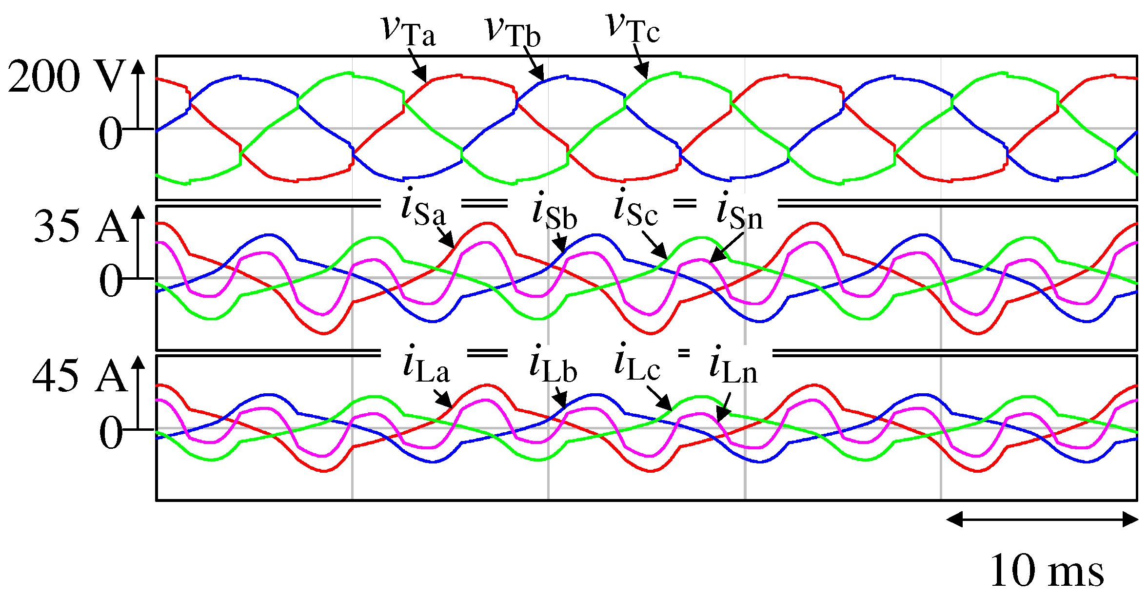
Figure 3 presents the simulation results without the proposed phase-specific reactive power control strategy. Here, , , and are the receiving-end voltage waveforms, , , , and are the secondary-side source current waveforms. , , , and are the load current waveforms flowing into the domestic consumers. The NPC inverter and LC filter are removed from the power circuit shown in Figure 4 and do not act as compensators.
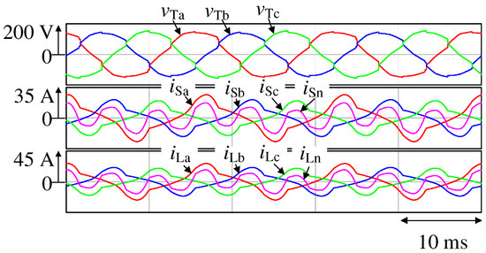
Figure 3.
Simulation results for Figure 2.

Figure 4.
Power circuit diagram of the proposed NPC-inverter-based APLC.
Therefore, the waveforms of the source and load sides are identical. The total harmonic distortion (THD) values of the source currents , , and and the load curves , , and matched perfectly (Table 3); both are unbalanced and heavily distorted. Here, the neutral-line current is not suppressed. Thus, on the source side, the RMS value of the a-phase current is 15.0 Arms, is 11.9 Arms, and is 11.0 Arms. Further, the neutral-line current is 10.5 Arms, which corresponds to 60% of the rated load current. The measured displacement power factor (DPF) values for phases a, b, and c are 0.87, 0.86, and 0.87, respectively. These values are far from a unity DPF. The RMS values of the receiving-end voltages are 108.1, 102.3, and 107.3 Vrms, exhibiting a large voltage drop. In particular, drops 11% from the reference receiving-end voltage value of 115 Vrms, which deviates from the IEC 60038 standard.
Table 3.
THD values for Figure 3.
3. Proposed Receiving-End Voltage Compensation with NPC-Inverter-Based APLC in 3P4WDF
Figure 4 shows the power circuit diagram of the proposed neutral-point-clamped (NPC) inverter-based APLC in 3P4WDF. This APLC uses the proposed receiving-end voltage compensation method. The APLC features a four-leg NPC inverter, with its fourth leg connected to a neutral line. NPC inverters, which are three-level inverters, can reduce the withstand voltage of the switching element compared with two-level inverters. In addition, since the switching noise is also reduced, the size of the LC filter can be reduced, and the switching frequency can be increased, enabling high-efficiency power conversion [38,39,40]. Our research group confirmed the basic principle of the reactive current control method by injecting arbitrary reactive current components in [18]. It was then shown that individual-phase unbalanced source currents can be achieved by injecting reactive currents for each phase separately. In this paper, a new control block is added to detect the reactive current component required for individual-phase receiving-end voltages compensation.
In Figure 4, a three-phase phase-locked loop (PLL) is used to produce the electric angle . is synchronized with the receiving-end voltage . The receiving-end voltages , , and are expressed as follows:
The unbalanced and distorted load currents , , and are expressed as
When the source currents in the three phases are unbalanced, and it is defined that the reactive currents for each phase are , , and , the reference source currents , , and are expressed as
The derivations of the reactive currents , , and are described below. The neutral-line current is expressed as the sum of , , and . In (4), the sum of the first terms of each equation is zero; therefore, the current through the neutral line is the sum of the second term, which are the reactive current components. Therefore, the current flowing through the neutral line is expressed as
This equation indicates that the neutral-line current is not zero, that is, it is not suppressed. Hence, the reactive power is used to cancel . Further, , which is a component of the neutral-line current suppression, , is expressed as
Rewriting (6) in terms of the cosine component to express the active current, we obtain
The active currents in (7) are added to the reference source currents in (4) for each phase. Thus, the reference source currents , , and are expressed as
In (8), the sum of the first term of each equation is zero. Further, the reactive current component in the second term and the active current component in the third term cancel each other out. Consequently, the neutral-line current becomes , and the current that flows through the neutral line can be effectively reduced. Therefore, by injecting an arbitrary reactive current and determining the reference source currents , , and , the reactive power of each phase can be regulated while minimizing the neutral-line current.
Next, the extraction of reactive currents and their flows are described. The multiplication of the receiving-end voltages , , and with the calculated , , and in each respective phase yields the following
A moving average low-pass filter (MALPF) is used to extract the AC components in (9) because the instantaneous power that flows into and out of the APLC is all even-order components, and by adopting MALPF, which uses a moving average of half a cycle as a low-pass filter, it is possible to remove the even-order component, 2 component. The RMS values , , and of the receiving-end voltages are expressed as follows:
Finally, the reactive currents , , and are calculated using feedback control with a PI controller. Substituting this reactive current into (8) enables reactive power control, that is, compensation of the terminal voltages.
PI controllers in dq0 coordinates are used to control the output currents , , and of the APLC. Further, the gate signals for – are generated by using the sine-triangle intercept technique with a two-phase modulation.
4. Simulation Results
A computer simulation is performed using the PSIM circuit simulation software package to verify the effectiveness of the proposed control method. The circuit constants in Figure 4 are listed in Table 4. In Table 4, the cut-off frequency is designed to be 5.19 kHz. The reference DC-capacitor voltage is 400 Vdc because the line-to-line voltages on the source side are 200 Vrms. The is decided to smooth the DC voltage sufficiently. Table 5 shows the parameters of PI controllers for Figure 4. The gain of the PI controller is determined by trial and error. The method of determining the gain needs to be examined in detail in the future. The inductors , , and with 20% of the rated inductance are added to the primary-side feeders and the phase voltages on the primary side are unbalanced and set to 120 Vrms, 115 Vrms, and 110 Vrms, as in Figure 2.
Table 4.
Control constants for Figure 4.
Table 5.
Parameters of PI controllers for Figure 4.
4.1. Employing the Phase-Specific Reactive Power Control Strategy
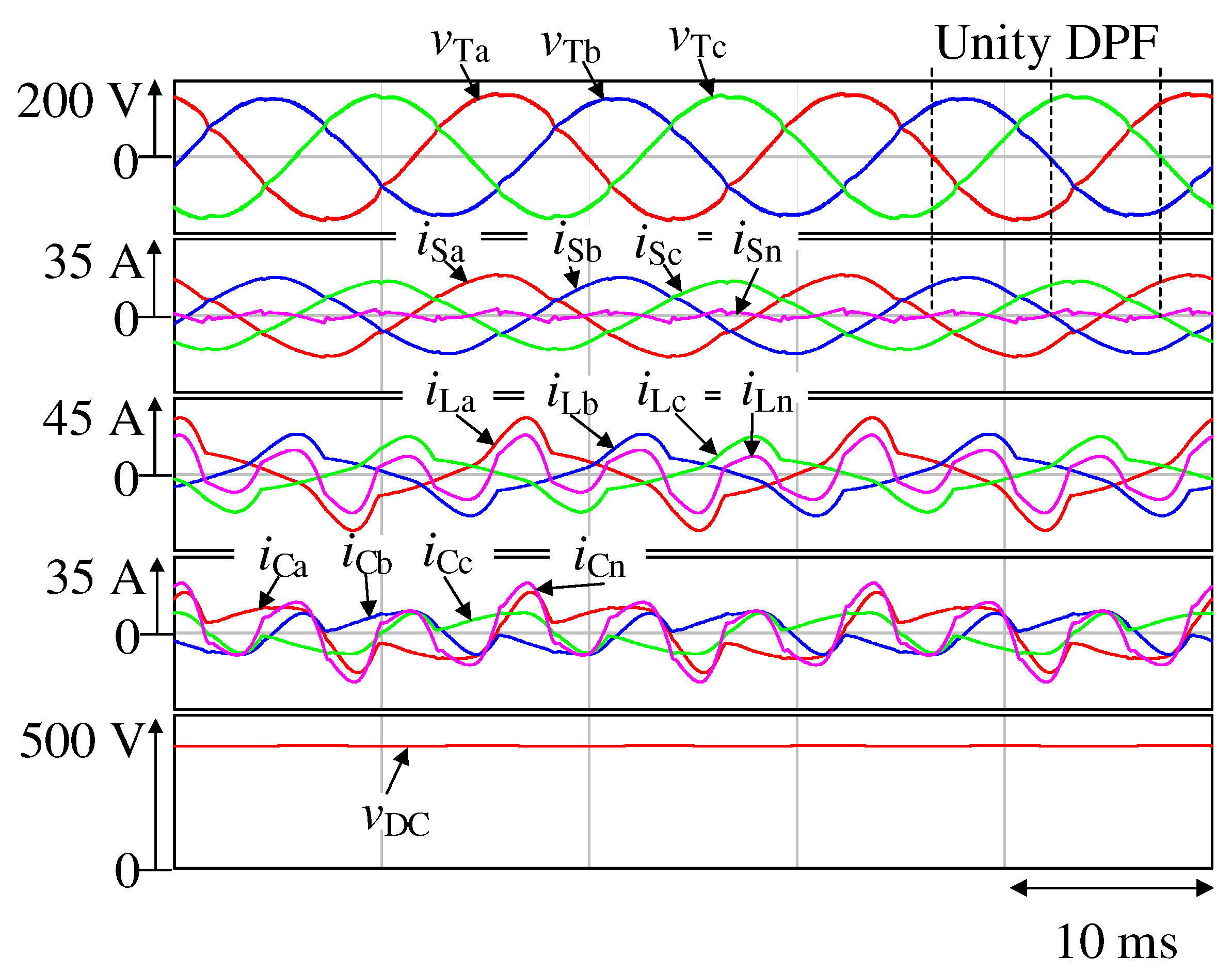
The simulation results for Figure 4 obtained using the proposed phase-specific reactive power control strategy are shown in Figure 5. Here, , , and are the receiving-end voltage waveforms, , , , and are the source current waveforms, , , , and are the load-current waveforms, , , , and are the output current waveforms of the four-leg NPC-inverter-based APLC, and is the DC-capacitor voltage waveform. The unbalanced and heavily distorted source currents , , and in Figure 3 are found to be balanced and sinusoidal owing to the compensation currents , , , and .
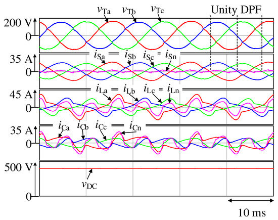
Figure 5.
Simulation results with proposed control strategy.
The THD values of , , and are 5.51%, 4.44%, and 4.38%, respectively, and those of , , and are 35.5%, 31.1%, and 32.1%, respectively (Table 6). The current in the neutral line, , is significantly reduced. Further, the source current’s RMS value for a-phase is 12.6 Arms, for b-phase is 11.9 Arms, and for c-phase is 10.7 Arms. Conversely, the neutral-line current is 1.39 Arms, which corresponds to 8.0% of the rated load current. In the a-phase, the DPF value between the terminal voltage and the source current is 1.00. Similarly, the DPFs are also 1.00 in b-phase and c-phase, respectively. The DPF values for each phase are maintained at unity. Table 7 lists the RMS values of the receiving-end voltages , , and in each phase prior to compensation in Figure 3 and after compensation in Figure 5 operation. The phase voltages on the primary side are set as 120, 115, and 110 Vrms, respectively. Before compensation, the RMS values of the receiving-end voltages are 108.1, 102.3, and 107.3 Vrms, exhibiting a large voltage drop. However, after compensation, the RMS values of the receiving-end voltages are 117.4, 109.4, and 113.8 Vrms, respectively. The voltage drops caused by the long-distance high-voltage distribution feeders increased. This confirmed the compensation at the receiving-end while satisfying the standards of IEC 60038. Moreover, the voltage of the DC-capacitor, , is effectively maintained at the reference value of 400 Vdc.
Table 6.
THD values for Figure 5.
Table 7.
Before and after comparison in terms of compensation of the RMS value of the receiving-end voltages.
Therefore, the receiving-end voltage can be compensated for by suppressing the neutral-line current using the proposed phase-specific reactive power control strategy.
4.2. Load Fluctuation for a Phase
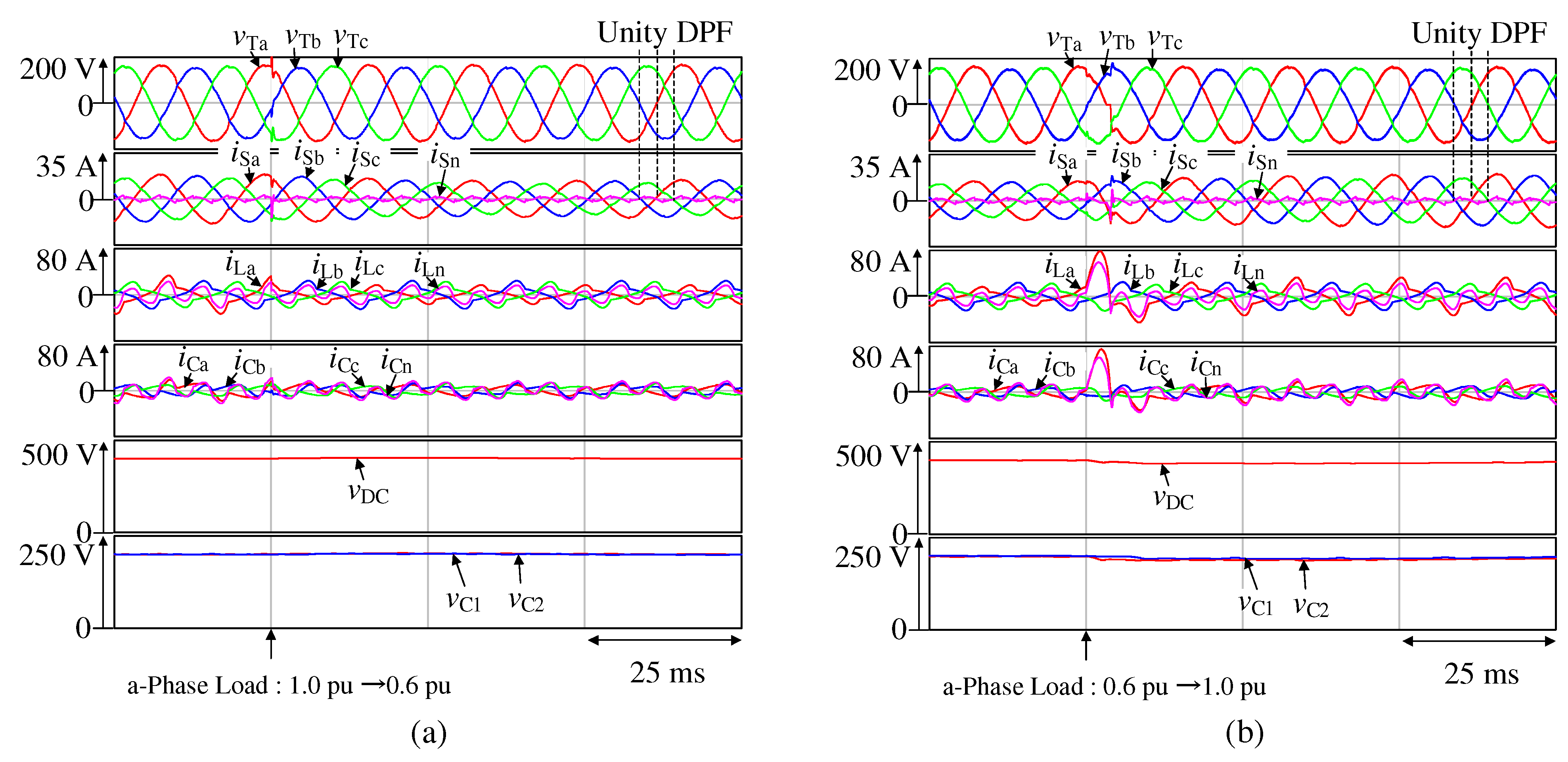
The simulation results for Figure 4, which presents the variation in the a-phase load, are shown in Figure 6a,b. Here, , , and are the receiving-end voltage waveforms, , , , and are the source current waveforms, , , , and are the load current waveforms, , , , and are the output current waveforms of the four-leg NPC-inverter-based APLC, is the DC-capacitor voltage waveform, and are the capacitor voltage waveforms, and is the neutral-line point voltage waveform.
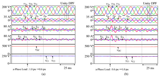
Figure 6.
Simulation results for Figure 4 showing the variation in the a-phase load from (a) 1.0 to 0.6 pu and (b) 0.6 to 1.0 pu.
Figure 6a illustrates the variation in the a-phase load from 1.0 to 0.6 pu. With the a-phase load of 0.6 pu, the THD values of , , and are 3.63%, 5.69%, and 5.96%, respectively, whereas those of , , and are 30.2%, 30.7%, and 32.8%, respectively. The DPF is well-controlled under a-phase load variation. The recorded DPF values for each phases are 1.00, respectively, for both 1.0 and 0.6 pu of a-phase load. The measured DPF values are consistent with the predetermined DPF values, which are unity. The voltage values of and , where , during load fluctuation, are almost uniformly distributed. The maximum difference between and is 1.1 Vdc, which is only a bias of 0.6%. The difference between the maximum and minimum values of is 5.3 Vdc, with an amplitude of 2.7%. Similarly, the difference between the maximum and minimum values of is 4.9 Vdc, which has an amplitude of 2.5%. Thus, even when load fluctuation occurred, the voltage values of and have no bias.
Figure 6b illustrates the variation in the a-phase load from 0.6 to 1.0 pu. With the a-phase load of 1.0 pu, the THD values of , , and are 5.50%, 4.50%, and 4.43%, respectively, whereas those of , , and are 35.5%, 31.1%, and 32.1%, respectively. The DPF is well-controlled under a-phase load variation. The recorded DPF values for phases a, b, and c are 1.00, respectively, for both 1.0 and 0.6 pu of a-phase load. The measured DPF values are consistent with the predetermined DPF values, which are unity. The maximum difference between the voltage values of and is only 4.2 Vdc. Further, the difference between the maximum and minimum values of is 14.6 Vdc, with an amplitude of 7.3%. Similarly, the difference between the maximum and minimum values of is 12.9 Vdc with an amplitude of 6.5%. Thus, even when load fluctuations occurred, the voltage values of and have no bias.
In Figure 6a, the maximum and minimum values of the DC-capacitor voltage, , are 405.8 and 398.6 Vdc. In Figure 6b, the maximum and minimum values of the DC-capacitor voltage, , are 407.2 and 382.9 Vdc, too. Thus, the fluctuation rate of the DC-capacitor voltage can be suppressed within 10%, which is practical. From the above, it can be confirmed that a quick recovery can be expected even under load fluctuations.
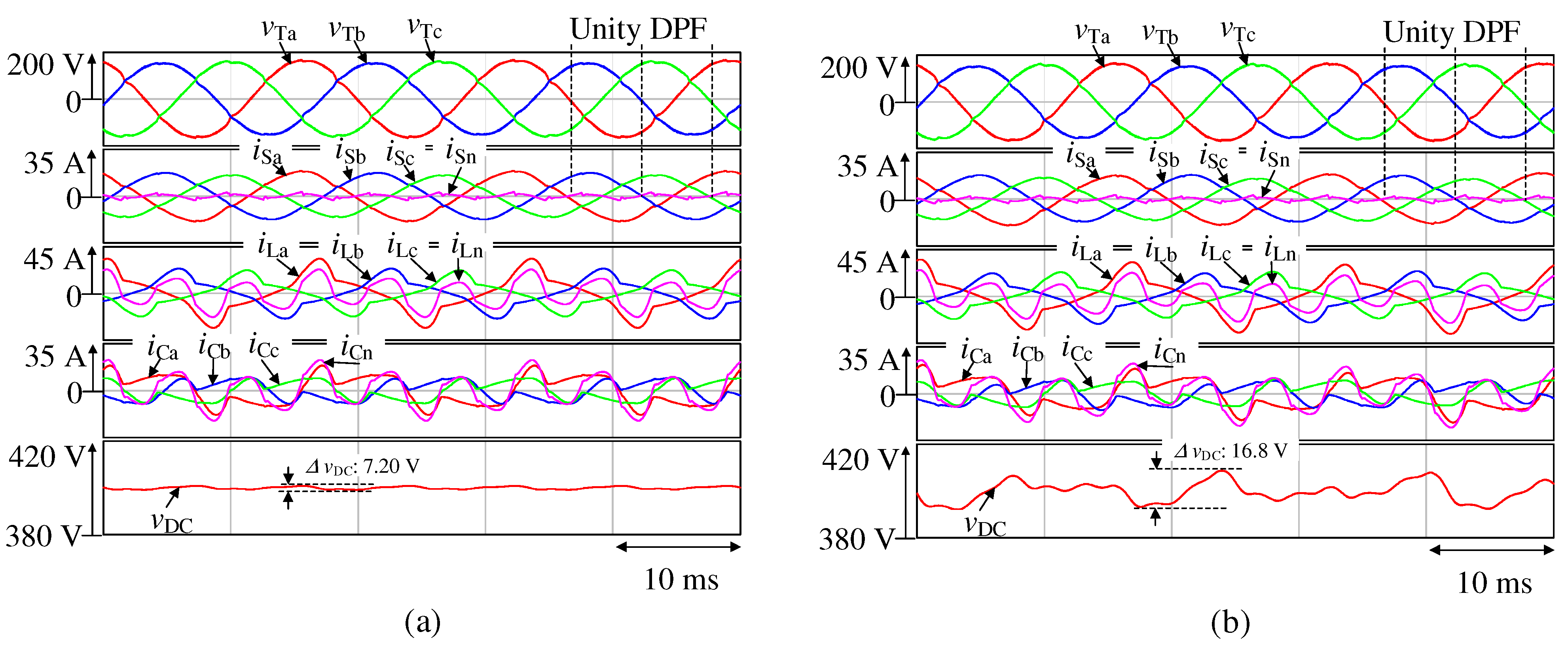
4.3. Relationship Between Capacitance of DC-Capacitor and THD
In this section, the relationship between the capacitances of the DC-capacitors and and THD is discussed. Figure 7a,b shows the simulation results with the phase-specific reactive power control strategy for different capacitances of the DC-capacitors and , respectively. Here, , , and are the receiving-end voltage waveforms, , , , and are the source current waveforms, , , , and are the load current waveforms, , , , and are the output current waveforms of the four-leg NPC-inverter-based APLC, and is the DC-capacitor voltage waveform.
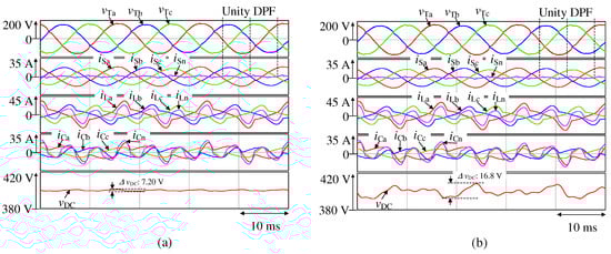
Figure 7.
Simulation results for and of (a) 3900 µF and (b) 700 µF.
In Figure 7a, the measured DPF values for each phase are 1.00, and the RMS value of the neutral-line current is 1.39 Arms, which corresponds to only 8.0% of the rated load current. The THD values of , , and are 5.51%, 4.44%, and 4.38%, respectively, whereas those of , , and are 35.5%, 31.1%, and 32.1%, respectively.
In Figure 7b, the measured DPF values for each phase are 1.00 and the RMS value of the neutral-line current is 1.37 Arms, which corresponds to only 7.9% of the rated load current. The THD values of , , and are 6.33%, 6.39%, and 5.08%, respectively, whereas those of , , and are 36.2%, 32.5%, and 32.8%, respectively.
Table 8 indicates the THD values for Figure 7a,b. From Table 8, the compensation performance is almost the same. Therefore, the same results are obtained regardless of whether the and are 3900 µF or 700 µF. Thus, the capacitances of DC-capacitors and are successfully miniaturized.
Table 8.
THD values for Figure 7a,b.
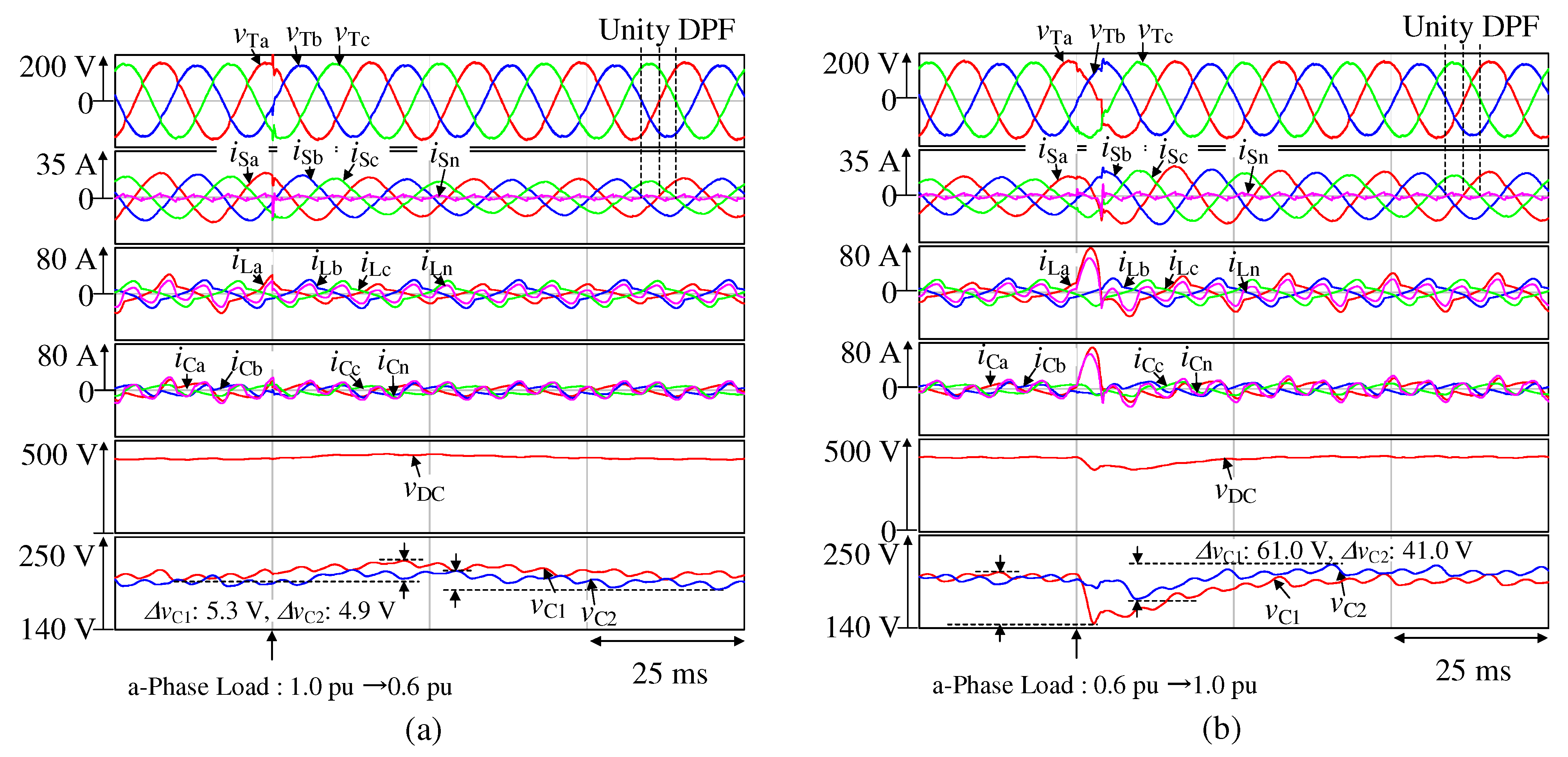
The simulation results for Figure 4, which is the variation in the a-phase load with the capacitances of DC-capacitors and of 700 µ, F are shown in Figure 8a,b. Here, , , and are the receiving-end voltage waveforms, , , , and are the source current waveforms, , , , and are the load current waveforms, , , , and are the output current waveforms of the four-leg APLC, is the DC-capacitor voltage waveform, and and are the capacitor voltage waveforms.
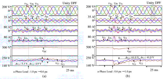
Figure 8.
Simulation results for Figure 4 with the capacitance of DC-capacitor of 700 µF, depicting the changes in the a-phase load from (a) 1.0 to 0.6 pu and (b) 0.6 to 1.0 pu.
Figure 8a illustrates the variation in the a-phase load from 1.0 to 0.6 pu. With an a-phase load of 0.6 pu, the THD values of , , and are 4.31%, 5.69%, and 5.52%, respectively, whereas those of , , and are 30.6%, 30.9%, and 32.5%, respectively. The DPF values are well-controlled under a-phase load variation. The measured DPF values for each phases are 1.00. The measured DPF values are consistent with the predetermined DPF values, which are unity. The voltage values of and , where , during the load fluctuation are almost uniformly distributed. The maximum difference between and is 5.5 Vdc, which is only a bias of 2.8%. The difference between the maximum and minimum values of is 16.4 Vdc. The ripple ratio of is approximately 8.2%. Similarly, the difference between the maximum and minimum values of is 17.5 Vdc. The ripple ratio of is approximately 8.8%. Thus, even when load fluctuations occurred, the voltage values of and have no bias.
Figure 8b illustrates the variation in the a-phase load from 0.6 to 1.0 pu. With the a-phase load of 1.0 pu, the THD values of , , and are 5.16%, 4.51%, and 4.48%, respectively, whereas those of , , and are 35.6%, 31.1%, and 32.1%, respectively. The DPF values are well-controlled under the a-phase load variation. The measured DPF values for each phases are 1.00 for both 1.0 pu and 0.6 pu of a-phase load. The measured DPF values are consistent with the predetermined DPF values, which are unity. The maximum difference between the voltage values of and is only 29.1 Vdc. The difference between the maximum and minimum values of is 61.0 Vdc with an amplitude of 30.5%. Similarly, the difference between the maximum and minimum values of is 41.0 Vdc with an amplitude of 20.5%. Thus, even when load fluctuations occurred, and were balanced.
In Figure 6a, the maximum and minimum values of the DC-capacitor voltage, , are 427.3 and 395.5 Vdc. In Figure 6b, the maximum and minimum values of the DC-capacitor voltage, , are 405.4 and 334.3 Vdc, too. Thus, the fluctuation rate of the DC-capacitor voltage can be suppressed around 10%, which is practical. From the above, it can be confirmed that a quick recovery can be expected even under load fluctuations.
5. Conclusions
This study proposed a method for compensating the receiving-end voltage in 3P4WDF systems using a phase-specific reactive power control strategy implemented with a four-leg APLC using an NPC inverter. The method effectively reduced the neutral-line current. The reference source currents were determined using a derivation block to calculate the reactive current and equations incorporating the active component. When the phase-specific reactive power control was applied using these calculated source currents, sinusoidal currents were generated on the source side; however, the neutral-line current was larger. This study proposed redistributing the active components on the source side to mitigate this issue. By redistributing these active components, the neutral-line current was suppressed while maintaining unity DPFs in each phase. The simulation results show that the proposed phase-specific reactive power control strategy successfully compensated for the receiving-end voltage and achieved sinusoidal source currents with unity DPFs in each phase, thereby reducing the neutral-line current. In addition, it was confirmed that the proposed system quickly recovered and operated normally after the quickly recovery when the load varied. Furthermore, even when the capacitance of the DC-capacitor was reduced, no deterioration in the THD or DPF was observed. Therefore, this study demonstrated that successful operation can be achieved even with a small capacitance of the DC-capacitor. In the future, we will try to improve compensation performance for receiving-end voltage and harmonic current compensation by increasing the number of levels of NPC inverter.
Author Contributions
Conceptualization, Y.S. and H.Y.; methodology, Y.S.; software, Y.S.; validation, Y.S.; formal analysis, Y.S.; investigation, Y.S.; resources, H.Y.; data curation, Y.S.; writing—original draft preparation, Y.S.; writing—review and editing, H.Y.; visualization, Y.S.; supervision, H.Y. All authors have read and agreed to the published version of the manuscript.
Funding
This research received no external funding.
Institutional Review Board Statement
Not applicable.
Informed Consent Statement
Not applicable.
Data Availability Statement
The data are contained within this paper.
Conflicts of Interest
The authors declare no conflicts of interest.
References
- World Population Review. Available online: https://worldpopulationreview.com/country-rankings/voltage-by-country (accessed on 21 October 2024).
- Hu, Z.; Han, Y.; Zalhaf, A.S.; Zhou, S.; Zhao, E.; Yang, P. Harmonic Sources Modeling and Characterization in Modern Power Systems: A Comprehensive Overview. Electr. Power Syst. Res. 2023, 218, 1–25. [Google Scholar] [CrossRef]
- Li, C.; Burgos, R.; Wen, B.; Tang, Y.; Boroyevich, D. Stability Analysis of Power Systems With Multiple STATCOMs in Close Proximity. IEEE Trans. Power Electron. 2020, 35, 2268–2283. [Google Scholar] [CrossRef]
- Haw, L.K.; Dahidah, M.S.A.; Almurib, H.A.F. A New Reactive Current Reference Algorithm for the STATCOM System Based on Cascaded Multilevel Inverters. IEEE Trans. Power Electron. 2015, 30, 3577–3588. [Google Scholar] [CrossRef]
- Jung, J.-J.; Lee, J.-H.; Sul, S.-K.; Son, G.T.; Chung, Y.-H. DC Capacitor Voltage Balancing Control for Delta-Connected Cascaded H-Bridge STATCOM Considering Unbalanced Grid and Load Conditions. IEEE Trans. Power Electron. 2018, 33, 4726–4735. [Google Scholar] [CrossRef]
- Lu, D.; Wang, S.; Yao, J.; Yang, T.; Hu, H. Cluster Voltage Regulation Strategy to Eliminate Negative-Sequence Currents Under Unbalanced Grid for Star-Connected Cascaded H-Bridge STATCOM. IEEE Trans. Power Electron. 2019, 34, 2193–2205. [Google Scholar] [CrossRef]
- Peng, F.Z.; Lai, J.-S. Dynamic performance and control of a static VAr generator using cascade multilevel inverters. IEEE Trans. Ind. Electron. 1997, 33, 748–755. [Google Scholar] [CrossRef]
- Cheng, Y.; Qian, C.; Crow, M.L.; Pekarek, S.; Atcitty, S. A Comparison of Diode-Clamped and Cascaded Multilevel Converters for a STATCOM With Energy Storage. IEEE Trans. Ind. Electron. 2006, 53, 1512–1521. [Google Scholar] [CrossRef]
- Lu, D.; Hu, H.; Xing, Y.; He, X.; Sun, K.; Yao, J. Studies on the clustered voltage balancing mechanism for cascaded H-bridge STATCOM. In Proceedings of the 2016 IEEE Applied Power Electronics Conference and Exposition (APEC), Long Beach, CA, USA, 20–24 March 2016; pp. 2194–2199. [Google Scholar]
- Djeghloud, H.; Bentounsi, A.; Benalla, H. Simulation of a DFIG-based wind turbine with active filtering function using Matlab/Simulink. In Proceedings of the XIX International Conference on Electrical Machines—ICEM 2010, Rome, Italy, 6–8 September 2010; pp. 1–7. [Google Scholar]
- Gaillard, A.; Poure, P.; Saadate, S. Active filtering capability of WECS with DFIG for grid power quality improvement. In Proceedings of the 2008 IEEE International Symposium on Industrial Electronics, Cambridge, UK, 30 June–2 July 2008; pp. 2365–2370. [Google Scholar]
- Wessels, C.; Hoffmann, N.; Molinas, M.; Fuchs, F.W. StatCom control at wind farms with fixed-speed induction generators under asymmetrical grid faults. IEEE Trans. Ind. Electron. 2013, 60, 2864–2873. [Google Scholar] [CrossRef]
- Aredes, M.; Hafner, J.; Heumann, K. Three-phase four-wire shunt active filter control strategies. IEEE Trans. Power Electron. 1997, 12, 311–318. [Google Scholar] [CrossRef]
- Nava-Segura, A.; Mino-Aguilar, G. Four-branches-inverter-based-active-filter for unbalanced 3-phase 4-wires electrical distribution systems. In Proceedings of the Conference Record of the 2000 IEEE Industry Applications Conference. Thirty-Fifth IAS Annual Meeting and World Conference on Industrial Applications of Electrical Energy (Cat. No.00CH37129), Rome, Italy, 8–12 October 2000; Volume 4, pp. 1–6. [Google Scholar]
- Sawant, R.R.; Chandorkar, M.C. A multifunctional four-leg grid-connected compensator. IEEE Trans. Ind. Appl. 2009, 45, 249–259. [Google Scholar] [CrossRef]
- El-Sotouhy, M.M.; Zaki, A.M.; Mansour, A.A.; El-Sattar, A.A.; Marei, M.I. Active filter based on four-leg inverter and PQ theory. In Proceedings of the 2019 21st International Middle East Power Systems Conference (MEPCON), Cairo, Egypt, 17–19 December 2019; pp. 1057–1062. [Google Scholar]
- Sabi, Y.; Yamada, H.; Tanaka, T.; Ikeda, F.; Okamoto, M.; Lee, S.R. Individual-Phase Displacement Power Factor Control Strategy of an Active Power-Line Conditioner in Three-Phase Four-Wire Distribution Feeders. In Proceedings of the 2022 International Power Electronics Conference (IPEC-Himeji 2022-ECCE-Asia), Himeji, Japan, 16–19 May 2022; pp. 2207–2212. [Google Scholar]
- Sabi, Y.; Yamada, H.; Tanaka, T.; Ikeda, F.; Okamoto, M.; Lee, S.R. Individual-Phase Direct Reactive Current Control Strategy for an Active Power-Line Conditioner in Three-Phase Four-Wire Distribution Feeders. In Proceedings of the 11th International Conference on Power Electronics (ICPE2023-ECCE-Asia), Jeju, Republic of Korea, 22–25 May 2023; pp. 799–804. [Google Scholar]
- Sabi, Y.; Yamada, H.; Tanaka, T.; Ikeda, F.; Okamoto, M.; Lee, S.R. Individual-Phase Fundamental Reactive Current Control Strategy with Suppressed Neutral-Line Current for an Active Power-Line Conditioner in Three-Phase Four-Wire Distribution Feeders. In Proceedings of the IEEE Energy Conversion Congress and Exposition (ECCE 2023), Nashville, TN, USA, 29 October–2 November 2023; pp. 972–977. [Google Scholar]
- Shuai, Z.; Xiao, M.; Ge, J.; Shen, Z.J. Overcurrent and its restraining method of pq-controlled three-phase four-wire converter under asymmetrical grid fault. IEEE J. Emerg. Sel. Top. Power Electron. 2019, 7, 2057–2069. [Google Scholar] [CrossRef]
- Aredes, M.; Watanabe, E.H. New Control algorithms for series and shunt three-phase four-wire active power filters. IEEE Trans. Power Deliv. 1995, 10, 1649–1656. [Google Scholar] [CrossRef]
- Kim, H.; Blaabjerg, F.; Bak-Jensen, B.; Choi, J. Instantaneous power compensation in three-phase systems by using p-q-r theory. IEEE Trans. Power Electron. 2002, 17, 701–710. [Google Scholar]
- Wu, J.-C.; Jou, H.-L.; Hsaio, H.-H.; Xiao, S.-T. A new hybrid power conditioner for suppressing harmonics and neutral-line current in three-phase four-wire distribution power systems. IEEE Trans. Power Deliv. 2014, 29, 1525–1532. [Google Scholar] [CrossRef]
- Modesto, R.A.; da Silva, S.A.O.; de Oliveira, A.A.; Bacon, V.D. A versatile unified power quality conditioner applied to three-phase four-wire distribution systems using a dual control strategy. IEEE Trans. Power Electron. 2016, 31, 5503–5514. [Google Scholar] [CrossRef]
- Campanhol, L.B.G.; da Silva, S.A.O.; de Oliveira, A.A.; Bacon, V.D. Power flow and stability analyses of a multifunctional distributed generation system integrating a photovoltaic system with unified power quality conditioner. IEEE Trans. Power Electron. 2019, 34, 6241–6256. [Google Scholar] [CrossRef]
- Hou, C.C.; Huang, Y.F. Design of single-phase shunt active filter for three-phase four-wire distribution systems. In Proceedings of the 2010 IEEE Energy Conversion Congress and Exposition, Atlanta, GA, USA, 12–16 September 2010; pp. 1525–1528. [Google Scholar]
- Li, Y.-C.; Tsai, T.-W.; Yang, C.-J.; Chen, Y.-M.; Chang, Y.-R. Per-Phase Control Strategy of the Three-Phase Four-Wire Inverter. In Proceedings of the 2018 International Power Electronics Conference (IPEC-Niigata 2018—ECCE Asia), Niigata, Japan, 20–24 May 2018; pp. 883–888. [Google Scholar]
- Chakraborty, S.; Mukhopadhyay, S.; Biswas, S.K. A Hybrid Compensator for Unbalanced AC Distribution System With Renewable Power. IEEE Trans. Ind. Appl. 2023, 59, 544–553. [Google Scholar] [CrossRef]
- Hintz, A.; Prasanna, U.R.; Rajashekara, K. Comparative Study of the Three-Phase Grid-Connected Inverter Sharing Unbalanced Three-Phase and/or Single-Phase systems. IEEE Trans. Ind. Appl. 2016, 52, 5156–5164. [Google Scholar] [CrossRef]
- Patel, N.; Gupta, N.; Babu, B.C. Photovoltaic System Operation as DSTATCOM for Power Quality Improvement Employing Active Current Control. IET Gener. Transm. Distrib. 2020, 14, 3518–3529. [Google Scholar] [CrossRef]
- Khadkikar, V.; Chandra, A. An independent control approach for three-phase four-wire shunt active filter based on three H-bridge topology under unbalanced load conditions. In Proceedings of the 2008 IEEE Power Electronics Specialists Conference, Rhodes, Greece, 15–19 June 2008; pp. 4643–4649. [Google Scholar]
- Wu, T.-F.; Chou, T.-C.; Chen, K.-H.; Chang, C.-H. Capacitor-current compensation with fast voltage loop for D-∑ digital control based three-phase four-wire inverter. In Proceedings of the 2015 IEEE 2nd International Future Energy Electronics Conference (IFEEC), Taipei, Taiwan, 1–4 November 2015; pp. 1–6. [Google Scholar]
- Ghosh, R.; Narayanan, G. Control of Three-Phase, Four-wire PWM rectifier. IEEE Trans. Power Electron. 2008, 23, 96–106. [Google Scholar] [CrossRef]
- Zhong, Q.-C.; Liang, J.; Weiss, G.; Feng, C.; Green, T.C. H Control of the Neutral Point in Four-Wire Three-Phase DC-AC converters. IEEE Trans. Ind. Electron. 2006, 53, 1594–1602. [Google Scholar] [CrossRef]
- Chakraborty, S.; Mukhopadhyay, S.; Biswas, S.K. A Hybrid Compensator for Mitigation of Power Quality Issues in Distribution Systems. In Proceedings of the 2022 IEEE International Conference on Power Electronics Smart Grid, and Renewable Energy (PESGRE), Trivandrum, India, 2–5 January 2022; pp. 1–6. [Google Scholar]
- IEC 60038; Standard Voltages. IEC: Geneva, Switzerland, 2009.
- The Japan Electrical Association. Internal Wiring Regulations JEAC8001; The Japan Electrical Association: Tokyo, Japan, 2016; pp. 35–37. (In Japanese) [Google Scholar]
- Macnica. 3-Level Inverters and SiC Power Modules. Available online: https://www.macnica.co.jp/business/semiconductor/articles/microchip/140603/ (accessed on 15 October 2024).
- Takano, A. VFM control of a multi-level inverter. In Numazu National College of Technology Research Report; Numazu National College of Technology: Shizuoka, Japan, 2021; pp. 15–17. (In Japanese) [Google Scholar]
- Sharifzadeh, M.; Sheikholeslami, A.; Vahedi, H.; Ghoreishy, H.; Labbé, P.-A.; Al‐Haddad, K. Optimised harmonic elimination modulation extended to four-leg neutral-point-clamped inverter. IET Power Electron. 2016, 9, 441–448. [Google Scholar] [CrossRef]
Disclaimer/Publisher’s Note: The statements, opinions and data contained in all publications are solely those of the individual author(s) and contributor(s) and not of MDPI and/or the editor(s). MDPI and/or the editor(s) disclaim responsibility for any injury to people or property resulting from any ideas, methods, instructions or products referred to in the content. |
© 2024 by the authors. Licensee MDPI, Basel, Switzerland. This article is an open access article distributed under the terms and conditions of the Creative Commons Attribution (CC BY) license (https://creativecommons.org/licenses/by/4.0/).