Abstract
In this paper an efficient, compact, and cheap power source design for an off-grid PV water pumping system is investigated. The proposed system consists of a PV array, battery, three-port converter (TPC), three-phase voltage source inverter, and induction motor pump. Power is extracted from PV sources during the daytime and used to charge batteries through the three-port converter, then used later to supply load during the nighttime. An intelligent MPPT method is used to obtain PV maximum power; a jellyfish optimization technique with different control algorithms is used to optimize and tune controllers’ parameters among the system. Different modes for the TPC are discussed depending on PV power availability. The proposed system is simulated to assess system performance under different conditions; also the system is efficient with reduced number of components than conventional converters. A complete unified power management over PV input port, battery port, and load port has occurred for all operation modes. At all operation modes, the system has been feeding load without any unmet loads. A real case study in Al-Kharijah oasis is studied and simulation results are listed; for the Dom case DC bus ripple factor voltage percentage equals 0.8%, in the Dim case equals 3%, and in the Siso mode equals 9%.
1. Introduction
Egypt is aiming to increasing generated electricity from renewable sources to 42% by 2035, with wind providing 14%, hydropower 1.98%, photovoltaic (PV) 21.3%, and conventional energy sources 57.33% [1]. Clean energy production is a very important issue, as it can afford the required amount of energy needed; it also avoids environmental damage. Production of environmentally friendly energy helps improve system sustainability, controlling energy resources wisely. The United Nations announced that the world should move towards sustainability by achieving 17 sustainable goals as per the 2030 agenda [2]. One of these goals is to increase energy share in the global energy production to move towards a green energy future, also reducing harmful emissions to support health and welfare to all human beings [2]. A lack of electricity in remote areas is related to high poverty rates. There is a direct proportional relation between energy consumption and economic growth. Extending the electricity network to some remote areas would be very expensive; thus, using renewable energy sources is more economical. A hybrid micro grid renewable energy system that consists of (PV), a wind energy system, battery, and diesel generator is proposed to meet the energy requirements in a city called Bernice, located in the Red Sea, Egypt [3].
Water plays an important role in any country’s development, as development depends on water quality and quantity [4]. Pumps that are powered by diesel are widely used in irrigation applications. However, oil is very expensive, harmful, and burning it results in polluted emissions. Also, pumps’ maintenance costs are high, so it is important to find different alternatives. Renewable energy can limit the use of fossil fuel, as many researchers move towards solar powered pumping systems [4].
Different types of motors can be used for water pumping applications. The Brushless DC motor has a high efficiency between 80% and 90%, a high torque to weight ratio, and low maintenance. Efficiency of the system excluding the PV part can reach up to 50%. The switched reluctance motor has a higher efficiency and lower cost compared to the DC or induction motor (IM), as efficiency can reach 85% [4].
In solar PV pumping applications, IM is widely used, as it has a reliable mechanical design and good performance for certain load ranges, as induction motor drive (IMD) behaves like a constant speed motor [5].
The authors in [6] use a scheme to improve PV system efficiency. This can be achieved by using new MPPT techniques. This scheme is enhanced by investigating a PV generator and DC shunt motor using a fuzzy logic controller. A power electronics system based on a boost DC–DC converter is used along with the PV module to improve the performance by shifting the converter control input duty cycle [6]. In [7], the proposed converter can consider power flow and has a high voltage gain with fewer components; the switched capacitor and coupled inductor have succeeded to achieve high voltage gain.
Many types of DC–DC converters are used in water pumping systems for controlling DC bus voltage. The authors in [8] present a grid connected multi-source hybrid renewable energy system consisting of a multi-port DC–DC converter, and a DC–AC PWM power inverter. The converter has several input sources, PV modules, fuel cells, and wind turbine generators. The multi-port converter can maintain the DC output voltage of the sources to a regulated DC voltage matched with the inverter input, and can also track the maximum power point for different renewable sources. The study in [9] discusses a novel two-phase parallel bidirectional DC–DC converter; this converter combines advantages of a Z-source network and interleaved parallel structure effectively. A three-port converter (TPC) is one type of multi-port converter with a bidirectional port for energy storage system along with an input port and output port; no separate converter is required for ESS [10]. Proposed TPC topology in [11] is based on using auxiliary switches connected to active bridge at TPC ports to guarantee zero circulating current flow between the battery and PV.
TPC reduces the conversion, which is why it has higher efficiency, compact size, and unity power management over the three ports where centralized control can be applied. Different studies have investigated TPC converters, as shown in [12].
Numerous studies have been conducted on water pumping applications; however, there is a need for more studies on the possibility of utilizing renewable sources to construct a comfortable and sustainable watering system. This proposed study focuses on suppling the required energy to operate a sustainable system, by constructing an efficient, compact, and cheap design for an off-grid PV water pumping system using 3-phases (IM). This strategy is achieved using a very compact converter with a reduced number of components, high efficiency, and low cost. The system consists of PV modules, TPC, battery, LC filter circuit, inverter, and motor pump. A jellyfish optimization technique, intelligent MPPT technique, and control algorithm are used to control different modes of the TPC. The whole system is developed via utilizing the MATLAB/Simulink software to simulate the suggested model and performing the overall system analysis. Different modes for the TPC are discussed depending on PV power availability which is affected by the sun irradiation profile. First, the article describes and the model system components in detail. Second, it describes different control strategies and optimization tools applied on the system. The system has been designed based on a case study in Al-Kharijah oasis city, Egypt. Finally, the simulation results are listed and discussed with conclusions.
2. System Description
The proposed PV water pumping system in this study consists of a 5.6 kW PV array connected to the TPC input port, a non-isolated boost three-port converter, a battery connected to the second port of TPC, a charger controller, an LC filter circuit, a three-phase inverter, and a motor pump connected to the TPC output port, as shown in Figure 1.
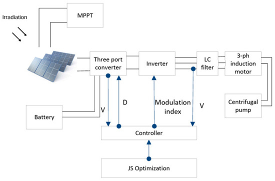
Figure 1.
Schematic diagram of the PV water pumping system.
When solar irradiation is highly available, the MPPT technique extracts maximum power from a PV system. The TPC supplies power to the IM pump through an inverter, and when there is excess energy, the TPC controls batteries’ charging process to save extra energy.
During cloudy and rainy days, PV power may be insufficient to feed load; the TPC controls the battery discharging process to supply load through inverter and filters. Each cycle, PV power and load power are calculated to determine which mode the TPC shall work in.
3. System Modeling
This section describes the system elements in detail; at first it describes the PV array used in the paper, the storage system, the TPC with different modes, the inverter, and the motor pump.
3.1. PV Array
In Figure 2, a photovoltaic array is composed of series and parallel modules. The following mathematical model is valid for any array that consists of Nser × Npar modules [13,14]:
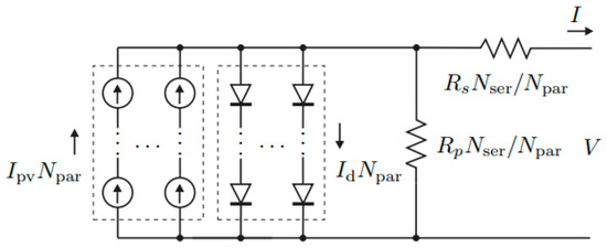
Figure 2.
The PV array has Nser and Npar modules [13].
3.2. Non-Isolated Three-Port DC–DC Boost Converter
The three-port DC–DC converter consists of three controlled semiconductor switches that turn on and off according to operating mode, three capacitors that are used to smooth the voltage and inductor, and three diodes. The controlled semiconductor switches (S1, S2, and S3) are used to extract the maximum power from the PV module, regulate the output voltage, and store the surplus power extracted from the PV module in the battery. The PV is connected to the input port (Vpv), load is connected to the output port (Vo), and the battery is connected to a bidirectional port in a single circuit (Vb). The TPC reduces the conversion stages, so the system is more efficient, has small packing, and a unified central power management is applied through three ports. Figure 3 shows a schematic diagram of the TPC [15].
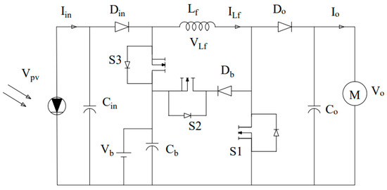
Figure 3.
Schematic diagram of the three-port converter.
3.3. Modes of Operation and Power Flow for TPC
The power flow of the converter is shown in Figure 4, where the PV inputs power to the converter (PPV), the load power (Pout), and the bidirectional power of the battery (Pbattery). According to the power–balance principle, the relation between the three ports’ power is obtained as [15]; TPC operating modes are determined based on the difference between PPV and Pbattery as described in Figure 4.
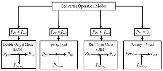
Figure 4.
TPC operating modes [15].
Figure 5 shows a flow chart that describes how each mode is being selected, indicating that it depends on (PPV–Pload).
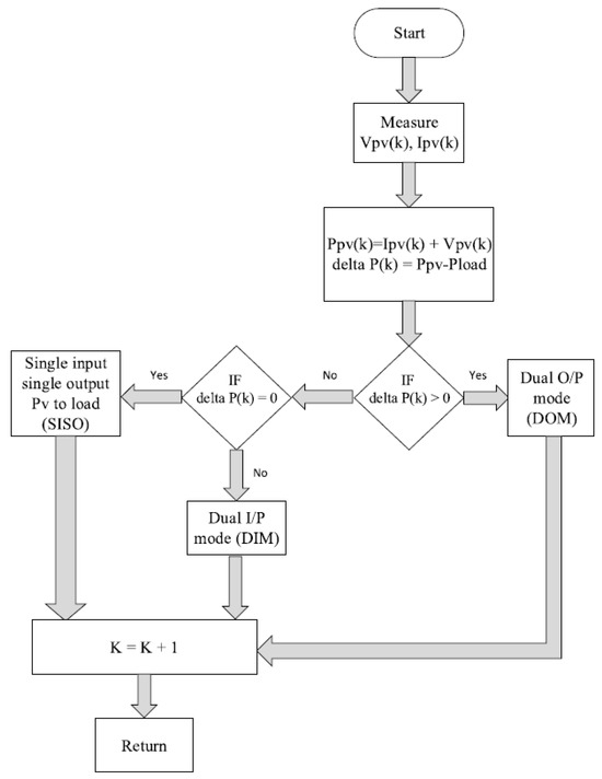
Figure 5.
Flow chart of TPC modes.
3.3.1. Dual Output Mode
The dual output mode (Dom) has three modes of operation. Mode I, when S1 is ON, S2 and S3 are OFF, is valid for a time interval of D1 × Ts. Mode II, when S2 is ON and S1 and S3 are OFF, is valid for a time interval of D2 × Ts. In mode III, all switches are OFF and it is valid for a time interval of (1 − D1 − D2) × Ts. Figure 6 describes the circuit diagram in the Dom mode:
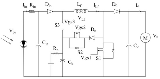
Figure 6.
Dom circuit diagram.
The state-space averaged model of the TPC in Dom can be expressed as [15]
3.3.2. Dual Input Mode (Dim)
When Ppv is less than the load power, PV and batteries share together to feed the load, which is called Dim mode. There are two cases in the Dim mode, when D1 > D3, and when D1 < D3.
When D1 > D3
In mode I interval, S1 and S3 are ON, and S2 is OFF is for a time equals D3×Ts. Mode II’s interval is for a time (D1 − D3) × Ts, where S1 is ON, and S2 and S3 are OFF. Mode III’s interval is for a time (1 − D1) × Ts, in which S1, S2, and S3 are OFF.
When D1 < D3
The mode I interval equals a time of D1 × Ts, in which S1 and S3 are ON, and S2 is OFF. The mode II interval equals (D3 − D1) × Ts, where S3 is ON, and S1 and S2 are OFF. The mode III interval equals (1 − D3) × Ts, in which S1, S2, and S3 are OFF.
Figure 7 shows the Dim circuit diagram. It is found that the two cases give the same ADim average matrix. Similarly, due to the matrices BDim, CDim, and EDim, the state-space averaged model of the TPC in Dim can be expressed as [15]:
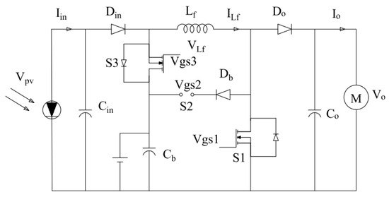
Figure 7.
Dim circuit diagram.
3.3.3. Single Input Single Output PV to Load (Siso)
This mode has two modes of operation. The mode I interval, equals a time of D1 × Ts, where S1 is ON, S2 and S3 are OFF. The mode II interval equals (1 − D1) × Ts, where S1, S2, and S3 are OFF. Figure 8 shows circuit diagram for the PV to load mode.
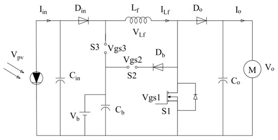
Figure 8.
PV to load (Siso) circuit diagram.
The state-space averaged model of the TPC in PV-load (Siso) can be expressed as [15]
3.3.4. Single Input Single Output Battery to Load (Siso)
This mode has two modes of operation. The mode I interval, equals a time of D1×Ts, in which S1 and S3 are ON, but S2 is OFF. Mode II interval is for a time (1 − D1) × Ts, where S3 is still ON but S1 and S2 are OFF. Figure 9 shows circuit diagram for the battery to load mode.
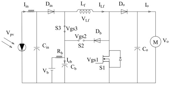
Figure 9.
Battery to load (Siso) circuit diagram.
The state-space averaged model of the TPC in battery-load (Siso) can be expressed as [15]
3.4. Modelling of Three-Phase Induction Motor
The motor model has four state variables: Istator components isd, isq, λrd, and ωr. The continuous state-space model for (IM) is shown as the following [16]:
A state-space vector given by x = [isd isq λrd ωr]T; u ∈ (2 × 1) is an input vector consisting of terminal voltage, indicated by u = [Vsd Vsq]T; δ ∈ (4 × 1) is the disturbance vector, given by δ = [0 0 0 (−p/Jt)Tl]T, with Jt that is total inertia moment of coupled rotating parts; and A(x) ∈ (4 × 4) is the matrix characteristics of the system, given by [16]:
With and as the stator transient time constant; is the rotor time constant; is the rotor transient time constant ; Lm is the magnetizing inductance; and ωs is the synchronous speed (rad/s), as following [16]:
in which ωslip is the slip speed. B ∈ (4 × 2) is input matrix given by [16]:
y ∈ (2 × 1) is output-matrix vector given by y = [λrd ωr]T; output matrix C ∈ (2 × 4) is given by
3.5. Pump Modelling Equations
The hydraulic power to drive a pump depends on liquid density, height to lift the fluid, and flow rate of the material [17]:
4. Control Strategies and Optimization
4.1. Control Strategies
The overall system discussed in this paper needs control over the following:
- PV power. Fuzzy logic is applied to gain maximum power from the PV array.
- A PI controller is used with the battery to regulate the DC bus voltage at reference value.
- A PI controller shall be used with the inverter to obtain a pure sinusoidal wave at the load terminals.
Figure 10 shows a fuzzy controller block diagram. Input signals can be processed by fuzzification block and fuzzy values are assigned for these signals. The data can be interpreted by the inference mechanism considering rules and their membership functions with the defuzzification block [18].
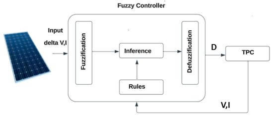
Figure 10.
Fuzzy controller block diagram.
The input variables are error € and change of error (CE) as a function of sample time (t) [18]:
The input E(t) is the P–V curve slope and defines the MPP position in the PV module, increment in the duty cycle (ΔD), and can be considered the output variable, which may be positive or negative depending on the operating point location. The DC–DC converter receives the output to operate the load. Using ΔD value delivered by the controller, an accumulator was made to obtain the value of the duty cycle.
4.2. Optimization
The jellyfish optimization technique is applied to obtain the optimal values of the PI controller gains. The JF optimization technique is a metaheuristic algorithm that observes the behavior in oceans. Simulation of search behavior by the JF technique includes following ocean current, active and passive motions inside a JF swarm, and their convergences into JF bloom as shown in Figure 11 [19].
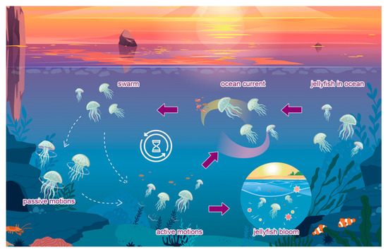
Figure 11.
JF movements in ocean [19].
The JF technique has been applied to selected PI gains with the following parameters values as shown in Figure 12.
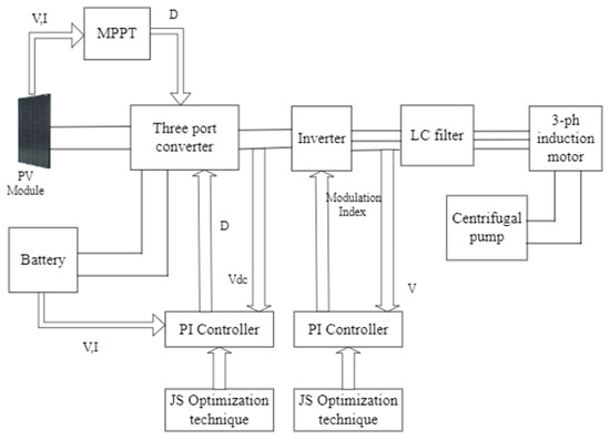
Figure 12.
System schematic diagram.
Population number = 40,
Number of iterations = 5,
The objective function for selecting PI gains is minimizing error signal as
The error signal (e) in the first PI controller equals VDC − Vload.
The error signal in the second PI is the difference between reference AC voltage and actual AC output voltage.
Direction of the ocean current () is determined by averaging all vectors using equation [19]:
New location of JF can be determined by the following [19]:
In swarm, jellyfish show passive (type A) and active (type B) motions, respectively. When the swarm is created, jellyfish mostly exhibit type A motions, then they increasingly exhibit type B motions. Type A motion is the motion of JF is given by [19]:
The simulation of JF motion and direction location and updated location respectively can be calculated by [19]:
Figure 13 shows JF algorithm flow chart. Two cascaded PI controllers are connected to the TPC and battery in order to regulate DC bus voltage; the third PI controller is connected to the inverter to obtain a pure sinusoidal waveform. Table 1 lists all PI controller gains.
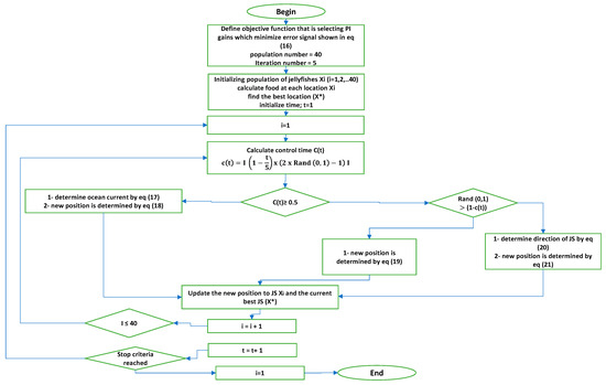
Figure 13.
JF algorithm flowchart.

Table 1.
PI Controller gains.
5. System Design
The Al-Kharijah oasis is located in the Western desert, around 200 km to the west of the Nile valley, Al-Kharijah’s coordinates are 25°26′18″ N 30°33′30″ E [20]. A group of five houses are located in Egypt’s AL-Kharijah Oasis. Each house consists of four members; the average consumption of water is 0.83 m3/h, so total consumption is 4.1 m3/h. Water pump parameters are selected and shown in Table 2. IM parameters are selected to be suitable enough to drive the water pump. The average solar energy throughout the year in the Al-Kharijah oasis is shown in Figure 14; also, Figure 15 shows the average number of daylight hours throughout the year [21].
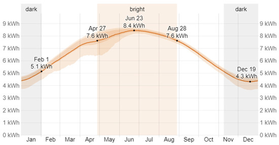
Figure 14.
Average daily incident shortwave solar energy in Al-Kharijah [21].
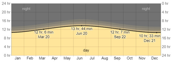
Figure 15.
Hours of daylight and twilight in Al-Kharijah [21].
Ppv can be calculated at head height 65 m with the following equation [22,23]:
where, g = 9.18 (m/s2), = 1000 (kg/m3), Qs = 20 (m3/day/house), G = 6.9 (kW/m2), Th = 65 (m), , and 1 for the pump are selected from [24], Substitute in Equation (17) then, Ppv = 5.7 kW. The PV array consists of five parallel strings, and six series modules per string. PV module data and TPC circuit parameters are calculated and listed; motor parameters are selected as shown in Table 2 [25].

Table 2.
System parameters [25].
Table 2.
System parameters [25].
| PV module power (W) | 195.4 |
| Voc open circuit voltage (V) | 45 |
| Isc short circuit current (A) | 5.56 |
| Voltage at maximum power (V) | 37.5 |
| Current at maximum power (A) | 5.21 |
| Number of cells per module | 72 |
| Battery type | Lithium-ion |
| Battery nominal voltage (V) | 12 × 25 |
| Initial state of charge (%) | 75 |
| Rated battery capacity (AH) | 250 |
| Capacitor Cin (µF) | 300 |
| Inductor Lf (mH) | 3 |
| Capacitor Co (µF) | 500 |
| Motor rated power (hp) | 5.5 |
| Motor nominal voltage (V) | 400 |
| Motor rated speed (rpm) | 1430 |
| Pump rated power (hp) | 5 |
| Max. head height (m) | 95 |
| Pump body material | Stainless steel |
6. Simulation Results and Discussion
The system described in Figure 1 has been simulated at different TPC modes. Each mode of the TPC has been simulated, and results are listed in each mode.
- Case study I: Dual output mode (Dom)
In this mode, the sun irradiance is about 1000 W/m2. The PV output power is high enough to operate the motor, with excess power to charge the batteries; the motor operates at rated torque 27 N.m. The previously discussed control technique manages to set the DC bus voltage to 600 V, as shown in Figure 16a. The maximum DC bus ripple factor voltage percentage equals nearly 0.8%, as shown in Figure 16b.
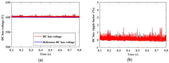
Figure 16.
(a) DC bus voltage. (b) DC bus percentage voltage ripple factor percentage.
Figure 17 shows the RMS value of three-phase AC line voltage (inverter output voltage) that equals about 380 V which is controlled by the previously discussed control technique, and an RMS value of three-phase AC current that equals nearly 8.5 A.
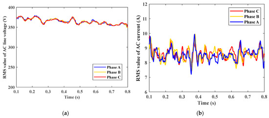
Figure 17.
(a) RMS value of three-phase AC output voltage. (b) RMS value of three-phase AC output current.
Figure 18 shows the motor speed, at rated torque speed which equals 1430 rpm as indicated. Also, motor actual torque is simulated which equals nearly 27 N.m.
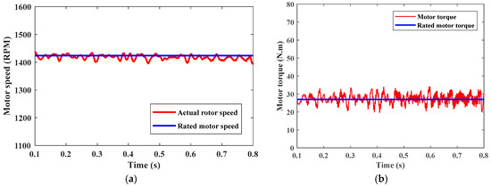
Figure 18.
(a) Motor speed. (b) Motor torque.
In this mode, the motor works at rated speed and rated torque, as PV supplies the motor with needed power.
Figure 19 shows the PV array output power which equals nearly 5.6 kW at irradiation 1000 W/m2 as MPPT is applied and PV power is at the maximum value; also load power equals 4 kW. It can be noticed that actual motor speed and actual PV power are at the rated values. Figure 20 shows Dom mode power management. It shows PV power, load power, and battery state of charge versus time, where the excess PV power charges batteries.
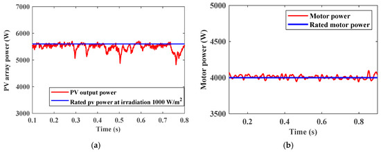
Figure 19.
(a) PV array output power. (b) Motor power.
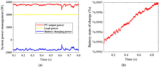
Figure 20.
(a) System power management. (b) Battery state of charge.
- Case II: Dual input mode (Dim)
In the dual input mode, PV irradiation is about 300 W/m2 and the motor operates at rated torque, so the PV output power is not high enough to operate this load, as PV equals nearly 1.6 kW; hence, the battery supplies more power. Figure 21 shows DC bus voltage and DC bus ripple factor. The DC bus ripple factor equals nearly 3%, which is higher than the Dom case, as in the Dim case, PV feeds load with less power than the Dom case; load is fed by both PV and batteries.
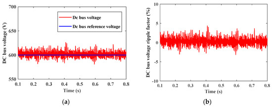
Figure 21.
(a) DC bus voltage. (b) DC bus voltage ripple factor percentage.
Figure 22 shows the RMS value of 3-phase AC line voltage that equals about 380 V, the RMS value for AC current at the Dim mode, which equals around 8.5 A, same as in the Dom case. Figure 23 shows the motor speed at rated torque where speed equals nearly 1430 rpm, and actual motor torque equals nearly 27 N.m. The motor works at rated speed and rated power as PV, and the batteries share in suppling load without interruptions, irrespective of sun irradiation.
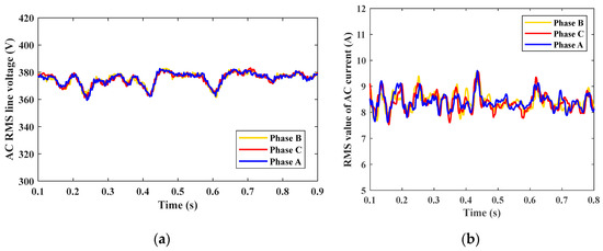
Figure 22.
(a) RMS value for the AC voltage. (b) RMS value for AC current.
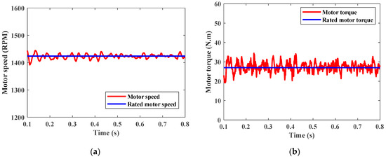
Figure 23.
(a) Motor speed. (b) Motor torque.
Figure 24 shows the PV array output power which equals about 1.6 kW, and load power equals around 4 kW.
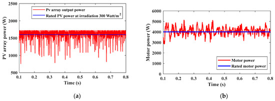
Figure 24.
(a) PV power. (b) Load power.
Figure 25a shows the Dim mode power management, as it shows PV power, load power, and battery discharging power. Figure 25b shows the battery state of charge where in Dim mode the batteries discharge power.
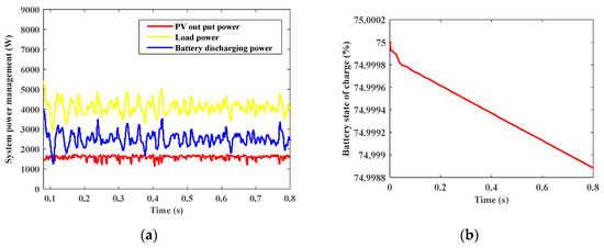
Figure 25.
(a) System power management. (b) Battery state of charge.
- Case III: Single input single output Siso (battery to load):
Siso mode is active when PV irradiation is not available at sunset or night times, so the PV output power equals zero, making battery responsible for motor operation. Siso mode is simulated when the motor operates at a torque rate of 27 N.m. Figure 26 shows DC bus voltage which is controlled at 600 V, and shows the DC bus ripple factor percentage equals nearly 9%, which is higher than previous modes, as battery only operates and PV power equals zero at Siso mode. Figure 27 shows the RMS value for the AC voltage which equals nearly 380 V, and the RMS value for AC current which equals nearly 8.5 A.
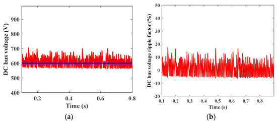
Figure 26.
(a) DC bus voltage. (b) DC bus voltage ripple factor percentage.
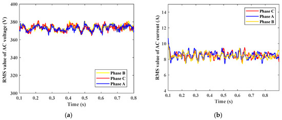
Figure 27.
(a) RMS value of three-phase AC output voltage. (b) RMS value of three-phase AC output current.
Figure 28 shows the motor speed at the rated torque which equals nearly 1430 rpm, and motor torque equals around 27 N.m. Figure 29 shows motor power which equals nearly 4 kW, and battery discharging power that nearly equals 4 kW. Figure 30 shows the battery state of charge where at Siso (Battery to load) mode batteries discharge power.
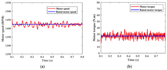
Figure 28.
(a) Motor speed. (b) Motor torque.
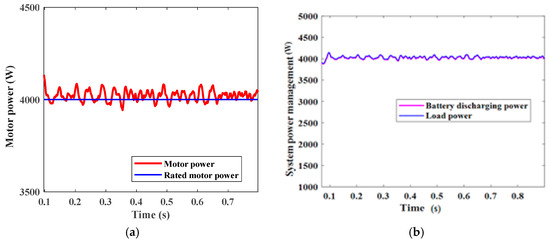
Figure 29.
(a) Motor power. (b) Battery discharging power.
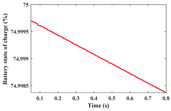
Figure 30.
Battery state of charge.
- Case IV: Simulation for (Dom-Dim-Siso battery to load) Modes Simultaneously
Each mode works depending on the difference between the PV power and the load power. If the PV power is greater than the load power, Dom mode starts working; if the PV power is less than the load power, then Dim mode starts working. Otherwise, Siso mode works. the system is simulated at selected torque that equals 15 N.m.
Figure 31 shows solar radiation, where at Dom the sun profile is high, almost 1000 W/m2, at Dim irradiation is 300 W/m2, and at the Siso no sun irradiation is available.
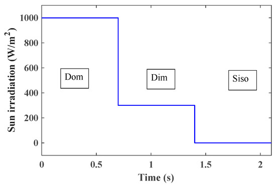
Figure 31.
Solar irradiations.
The DC bus voltage at different modes is shown simultaneously in Figure 32. There is a drop in the DC voltage at (0.7 s) due to the mode transition from Dom to Dim mode; also there is change at (1.4 s) due to transition from Dim to Siso mode. In this paper, control techniques are used to maintain DC bus voltage at 600 V. The DC bus voltage and DC bus voltage ripple factor are shown; it is clear that DC voltage ripples increase in the Siso mode when the battery operates to feed motor.
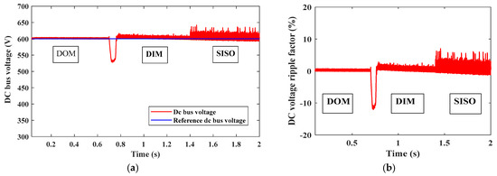
Figure 32.
(a) DC bus voltage. (b) DC bus voltage ripple factor percentage.
Figure 33 shows the RMS value of three-phase AC output voltage among different modes and the RMS value of three-phase AC output current. Figure 34 shows motor speed and motor torque.
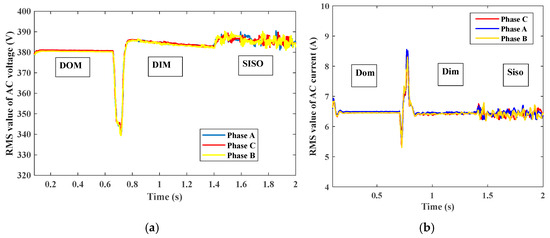
Figure 33.
(a) RMS value of three-phase AC output voltage. (b) RMS value of three-phase AC output current.
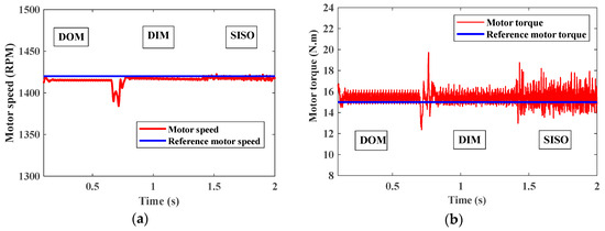
Figure 34.
(a) Motor speed. (b) Motor torque.
Figure 35 shows the PV output power among different modes, where power equals 5.6 kW/m2 in the Dom mode, 1.6 kW/m2 in the Dim mode, and zero in the Siso battery to load mode. The motor power equals nearly 2.2 kW as it works at a reduced torque of 15 N.m. The motor runs at a speed rate of 1430 as inverter output voltage is controlled at 380 V. Figure 36 shows the battery state of charge, where the battery charges in the Dom mode and discharges in the Dim and Siso modes.
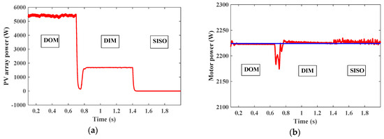
Figure 35.
(a) PV array output power. (b) Motor power.
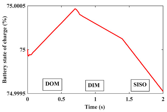
Figure 36.
Battery state of charge.
- Case study (V) Al-Kharijah Oasis
A real case study has been taken from the Al-Kharijah oasis; the solar irradiation on a random day in August has been studied. Each mode works depending on the difference between PV power and load power.
Figure 37 shows the average solar irradiation through the day where grey lines show corresponding days with minimum and maximum solar energy, also Figure 38 shows solar irradiation where the maximum radiation occurs between 11 am and 1 pm and the TPC works at Dom mode. The Dom mode works from nearly 8:30 am to 2 pm, where Dim mode works between 2 pm and 7:30 pm, and 7 am and 8:30 am. The Siso works for the rest of the hours when there is no available sun irradiation.
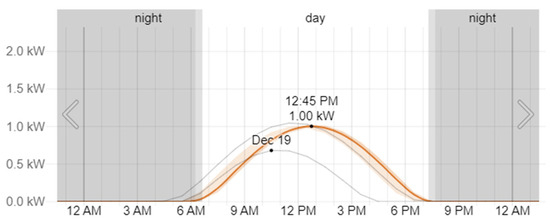
Figure 37.
Solar irradiation for a day in August [21].
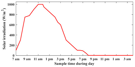
Figure 38.
Solar irradiations.
Figure 39 shows the DC bus voltage at different modes, where there is a drop in the DC voltage at (2 pm) due to mode transition from Dom to Dim mode; also, there is change at (8:30 pm) due to the transition from Dim to Siso mode. The DC bus voltage and DC bus voltage ripple factor are shown; it is clear that DC voltage ripples increase at the Siso mode when battery operates to feed motor.
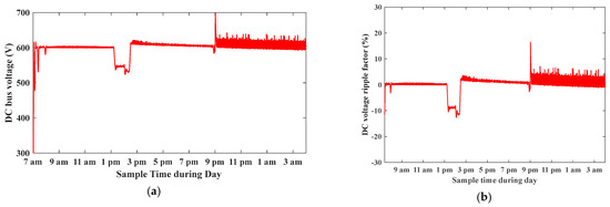
Figure 39.
(a) DC bus voltage. (b) DC bus voltage ripple factor percentage.
Figure 40 shows the RMS value of the three-phase AC output voltage among different modes, and the RMS value of three-phase AC output current. Figure 41 shows the motor speed at 1430 rpm and motor torque at 15 N.m. The motor power equals nearly 2.2 kW as it works at reduced torque of 15 N.m, and the motor runs at a speed rate of 1430 as the inverter output voltage is controlled at 380 V. Figure 42 shows the PV output power among different modes, where power is high in the Dom mode and charges battery, low at the Dim mode and battery shares with PV feeding load, and has zero power in the Siso battery to load mode. Figure 43 shows the battery state of charge, where the battery charges in the Dom mode between 9 am and 2 pm, and discharges in the Dim and Siso modes. Figure 44 shows the THD value of AC current, and the THD value of AC voltage respectively. See Table 3 for more details of individual measurements.
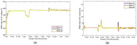
Figure 40.
(a) RMS value of three-phase AC output voltage. (b) RMS value of three-phase AC output current.
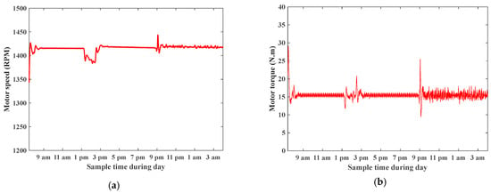
Figure 41.
(a) Motor speed. (b) Motor torque.

Figure 42.
(a) PV array output power. (b) Motor power.
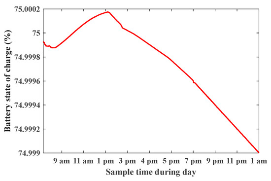
Figure 43.
Battery state of charge.
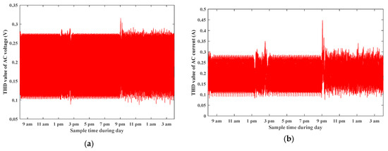
Figure 44.
(a) THD value of three-phase AC output voltage. (b) THD value of three-phase AC output current.

Table 3.
Individual measurements of the Al-Kharijah system case study.
7. Conclusions
The proposed system consists of the PV array, TPC converter, batteries, and 3-ph induction motor, all of which are used together in the water pumping application. The fuzzy logic MPPT technique is applied on the PV system to extract maximum output power, and the jellyfish optimization technique is applied to system controllers to optimize controller gains and system parameters. The proposed system is efficient due to a reduced number of components compared to conventional converters. A real case study in the Al-Kharijah oasis is studied and simulation results are listed. In the Dom case, the DC bus ripple factor voltage percentage is 0.8%, in the Dim case it equals 3%, and in the Siso mode it equals 9%. These advantages make the proposed system suitable for Standalone PV-Based pumping applications.
Author Contributions
Conceptualization, M.S., M.Z.E.s., M.S.N. and I.M.A.; Data curation, M.S. and I.M.A.; Formal analysis, M.S.N.; Funding acquisition, M.Z.E.s.; Methodology, M.S.N.; Resources, M.Z.E.s.; Supervision, M.Z.E.s. and I.M.A.; Validation, M.S. and I.M.A.; Visualization, M.S.N.; Writing—original draft, M.S.N.; Writing—review & editing, M.S. and I.M.A. All authors have read and agreed to the published version of the manuscript.
Funding
This research received no funding.
Data Availability Statement
No new data were created or analyzed in this study. Data sharing is not applicable to this article.
Conflicts of Interest
The authors declare no conflicts of interest.
Nomenclature
| ADom | System matrix during Dom |
| ADim | System matrix during Dim |
| BDom | Input matrix during Dom |
| BDim | Input matrix during Dim |
| Co | Output capacitor (F) |
| Cb | Battery capacitor (F) |
| Cin | Input capacitor (F) |
| CDom | Output matrix during Dom |
| CDim | Output matrix during Dim |
| D1 | Duty cycle for switch 1 |
| D2 | Duty cycle for switch 2 |
| D3 | Duty cycle for switch 3 |
| Small signal perturbation | |
| Small signal perturbation | |
| DDom | Feedforward matrices during Dom |
| DDim | Feedforward matrices during Dim |
| g | Gravity acceleration (m/s2) |
| H | Total head in (m) |
| Id | Diode current (A) |
| Ipv | PV current (A) |
| I0 | Average output current (A) |
| Jt | Total inertia moment (kg.m2) |
| L′s | Stator Transient inductance (H) |
| Lr | Rotor inductance (H) |
| Npar | Number of parallel modules |
| Nser | Number of series modules |
| Ppv | PV input power (W) |
| Pout | Load power (W) |
| Pbattery | Battery power (W) |
| Q | Flow rate in (m3/s) |
| Rb | Battery resistance (Ω) |
| Rin | Input resistance (Ω) |
| Rp | Parallel resistance (Ω) |
| Rs | Series resistance (Ω) |
| RL | Load resistance (Ω) |
| Vo | Output voltage (V) |
| Vpv | PV input voltage (V) |
| Vcin | Input capacitor voltage (V) |
| Vcb | Battery capacitor voltage (V) |
| VLf | Inductor voltage (V) |
| Vgs1 | Gate signal voltage across switch 1 (V) |
| Vgs2 | Gate signal voltage across switch 2 (V) |
| Vgs3 | Gate signal voltage across switch 3 (V) |
| X* | Currently Jellyfish with best location in the swarm |
| ′r | Rotor transient time constant |
| ′ | Transient time constant |
| r | Rotor time constant |
| α | Diode ideality constant |
| ρ | Fluid density (kg/L) |
| Pump efficiency (%) | |
| System losses (%) | |
| µ | Mean location of all jellyfish |
| β | Distribution coefficient |
| γ | Motion coefficient |
| ꬾrd | Rotor flux (T) |
| λrd | Rotor flux (Wb) |
| ωs | Synchronous speed (rad/s) |
| ωr | Motor speed (rad/s) |
References
- Ministry of Electricity and Renewable Energy. 2024. Available online: http://www.moee.gov.eg/ (accessed on 15 March 2024).
- Salah, S.I.; Eltaweel, M.; Abeykoon, C. Towards a sustainable energy future for Egypt: A systematic review of renewable energy sources, technologies, challenges, and recommendations. Clean. Eng. Technol. 2022, 8, 100497. [Google Scholar] [CrossRef]
- Hemeida, A.M.; Omer, A.S.; Bahaa-Eldin, A.M.; Alkhalaf, S.; Ahmed, M.; Senjyu, T.; El-Saady, G. Multi objective multi-verse optimization of renewable energy sources-based micro-grid system: Real case. Ain Shams Eng. J. 2022, 13, 101543. [Google Scholar] [CrossRef]
- Verma, S.; Mishra, S.; Chowdhury, S.; Gaur, A.; Mohapatra, S.; Soni, A.; Verma, P. Solar PV powered water pumping system—A review. Mater. Today Proc. 2021, 46, 5601–5606. [Google Scholar] [CrossRef]
- Shukla, S.; Singh, B.; Shaw, P.; Al-Durra, A.; El-Fouly, T.H.M.; El-Saadany, E.F. A new analytical MPPT-based induction motor drive for solar PV water pumping system with battery backup. IEEE Trans. Ind. Electron. 2021, 69, 5768–5781. [Google Scholar] [CrossRef]
- Osman, N.; Khalid, H.M.; Sweidan, T.O.; Abuashour, M.I.; Muyeen, S. A PV powered DC shunt motor: Study of dynamic analysis using maximum power Point-Based fuzzy logic controller. Energy Convers. Manag. 2022, 15, 100253. [Google Scholar] [CrossRef]
- Luo, P.; Guo, L.; Xu, J.; Li, X. Analysis and design of a new non-isolated three-port converter with high voltage gain for renewable energy applications. IEEE Access 2021, 9, 115909–115921. [Google Scholar] [CrossRef]
- Almutairi, A.; Sayed, K.; Albagami, N.; Abo-Khalil, A.G.; Saleeb, H. Multi-port PWM dc-dc power converter for renewable energy applications. Energies 2021, 14, 3490. [Google Scholar] [CrossRef]
- Zhang, B.; Hong, D.; Wang, T.; Zhang, Z.; Wang, D. A novel two-phase interleaved parallel bi-directional DC/DC converter. Arch. Electr. Eng. 2021, 70, 219–231. [Google Scholar]
- Visal, A.; MKP, M.R. Performance Analysis of an Integrated Three Port Converter for BLDC Motor-Based Applications. 2022. Available online: https://ssrn.com/abstract=4288204 (accessed on 15 March 2024).
- Marei, M.I.; Alajmi, B.N.; Abdelsalam, I.; Ahmed, N.A. An integrated topology of three-port dc-dc converter for PV-battery power systems. IEEE Open J. Ind. Electron. Soc. 2022, 3, 409–419. [Google Scholar] [CrossRef]
- Wu, H.; Sun, K.; Ding, S.; Xing, Y. Topology derivation of non-isolated three-port DC–DC converters from DIC and DOC. IEEE Trans. Power Electron. 2013, 28, 3297–3307. [Google Scholar] [CrossRef]
- Villalva, M.G.; Gazoli, J.R.; Ruppert Filho, E. Modeling and circuit-based simulation of photovoltaic arrays. In 2009 Brazilian Power Electronics Conference; IEEE: New York, NY, USA, 2009. [Google Scholar]
- Haque, A.M.; Sharma, S.; Nagal, D. Simulation of photovoltaic array using MATLAB/Simulink: Analysis, comparison & results. Futur. Trends Eng. Sci. Humanit. Technol. 2016, 16, 60. [Google Scholar]
- Abdelrahman, S.; Selmy, M.; Hasaneen, K.M.; Abdel-Rahim, N. Analysis, design, and control of a non-isolated boost three-Port converter for PV applications. In Proceedings of the 2019 IEEE Conference on Power Electronics and Renewable Energy (CPERE), Aswan, Egypt, 23–25 October 2019; pp. 18–25. [Google Scholar]
- de Santana, E.S.; Bim, E.; Amaral, W.C.D. A predictive algorithm for controlling speed and rotor flux of induction motor. IEEE Trans. Ind. Electron. 2008, 55, 4398–4407. [Google Scholar] [CrossRef]
- Meakhail, T.; Seung, O.P. An improved theory for regenerative pump performance. Proc. Inst. Mech. Eng. Part. A J. Power Energy 2005, 219, 213–222. [Google Scholar] [CrossRef]
- Robles Algarín, C.; Taborda Giraldo, J.; Rodriguez Alvarez, O. Fuzzy logic based MPPT controller for a PV system. Energies 2017, 10, 2036. [Google Scholar] [CrossRef]
- Chou, J.S.; Truong, D.N. A novel metaheuristic optimizer inspired by behavior of jellyfish in ocean. Appl. Math. Comput. 2021, 389, 125535. [Google Scholar] [CrossRef]
- Britannica, Kharijah Oasis. Available online: https://www.britannica.com/place/Al-Kharijah (accessed on 15 March 2024).
- Weather Spark, Kharijah Oasis. Available online: https://weatherspark.com/ (accessed on 15 March 2024).
- Abo-Khalil, A.G.; Ahmed, S.S. Water pumping using powered solar system more than an environmentally alternative: The case of Toshka, Egypt. J. Energy Nat. Res. 2016, 5, 19–25. [Google Scholar] [CrossRef]
- Gad, H.E.; El-Gayar, S.M. Performance Prediction of a Proposed Photovoltaic Water Pumping System at South Sinai, Egypt Climate Conditions. In Proceedings of the 30th International Water Technology Conference, Hurghada, Egypt, 2009. [Google Scholar]
- DAB Pumps, DAB. 2024. Available online: https://www.dabpumps.com/en (accessed on 15 March 2024).
- Selmy, M.S.; Alsherif, M.Z.; Noah, M.S.E.; Abdelqawee, I.M. Standalone PV-Based Water Pumping System Optimization using Jellyfish Technique. Eng. Res. J.-Fac. Eng. 2023, 52, 94–100. [Google Scholar] [CrossRef]
Disclaimer/Publisher’s Note: The statements, opinions and data contained in all publications are solely those of the individual author(s) and contributor(s) and not of MDPI and/or the editor(s). MDPI and/or the editor(s) disclaim responsibility for any injury to people or property resulting from any ideas, methods, instructions or products referred to in the content. |
© 2024 by the authors. Licensee MDPI, Basel, Switzerland. This article is an open access article distributed under the terms and conditions of the Creative Commons Attribution (CC BY) license (https://creativecommons.org/licenses/by/4.0/).