Abstract
Lithium-ion battery cells are the fundamental components of all Energy Storage Systems (ESSs) used in electric vehicles (EVs). Increasing concerns about safety issues, particularly the response of battery cells to mechanical crushes that can lead to internal short circuits (ISCs) and potential thermal runaway (TR), necessitate detailed investigation. To evaluate the response of a battery under abuse conditions, a homogeneous finite element (FE) model of a battery cell was developed. This model employs a simplified representation of a battery cell where the internal properties are assumed to be uniform throughout the entire cell. A full factorial approach was utilized to determine the homogenized jellyroll material characteristics. A detailed FEM serves as a benchmark for validating the homogeneous battery model. While requiring less computational effort, the homogeneous model maintains sufficient accuracy, making it suitable for modelling entire battery packs, thanks to the reduced number of elements.
1. Introduction
One of the main risks connected to the abuse conditions of electric vehicles (EVs), and, therefore, of battery packs as well, is related to thermal runaway (TR), which causes an uncontrolled increase in temperature, which leads to a further increase in temperature and definitely to the risk of fire. Abuse mechanisms, such as crushing, can result in the failure of one of the jellyroll layers (the battery’s internal structure), which leads to an internal short circuit (ISC) and consequently causes an exothermic reaction, which eventually may initiate TR in the battery [1,2]. The main objectives of simulations are to predict and mitigate the TR risk of battery packs when undergoing crash scenarios (Figure 1). In order to do so, however, the first step is to design accurate, still computationally efficient single battery cell models. In this context, the homogeneous model represents a simplified approach [3], while the heterogeneous model, used as a benchmark in this study, provides a detailed representation of the jellyroll layered structure [4]. This research aims to build a proper homogeneous model of a single battery cell, which will be adopted for an entire battery pack system in future. In Section 2, the authors provide an overview of mechanical testing procedures per international and European standards. The homogeneous model, described in Section 3.1, is validated through a benchmark, the heterogeneous model, developed in a previous work of the same authors. The results of the simulations are provided in Section 4, in which the results of the proposed models are compared, and a best-fit material characteristic is proposed.
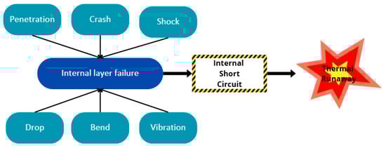
Figure 1.
Schematic view of abuse events that might cause thermal runaway.
2. Overview of International Standards for Abuse Conditions
International standards regarding abuse testing on lithium-ion battery cells are continuously evolving. These tests simulate conditions a battery might encounter during real-world use, mishandling, or accidents [5]. The main goal is to ensure that lithium-ion cells do not fail in ways that could lead to fire, explosion, or other hazardous outcomes under mechanical abuse, ensuring both safety and reliability. Table 1 provides an overview of international standards on mechanical testing; some of the most common include the following:

Table 1.
Overview of international standards on mechanical testing (C = cell; M = Module; P = pack).
- Impact Testing: In impact testing, a heavy object falling on a battery is simulated.
- Crush Testing: In crush testing, force is applied to compress the battery, simulating situations where a battery might be crushed.
- Penetration Testing: In penetration testing, a nail or other sharp object penetrates the battery, mimicking damage from punctures.
- Vibration Testing: In vibration testing, how batteries respond to sustained vibration is tested, replicating conditions in vehicles or machinery.
- Shock Testing: In shock testing, batteries are exposed to sudden acceleration or deceleration, like what might happen in a crash.
The main tests considered and replicated in the simulations in this work are the impact and indentation tests, which are represented in Figure 2. The first one consists of a cylindrical indenter placed at an orthogonal position to the battery under test (BUT) which is then impacted by a drop weight that strikes the indenter and, therefore, crushes the BUT [16]. The latter test (one of the most common in the literature [17,18,19,20]) consists of an indenter that hits the cell with a certain velocity. These tests were simulated and replicated in the heterogeneous and homogeneous models to compare the results.
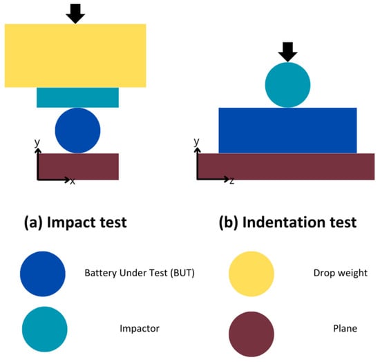
Figure 2.
Schematization of impact and indentation tests.
3. Battery Cell Finite Element Models
Several numerical models have been proposed in the literature to simulate battery cell behaviour under abuse conditions [4,21,22]. Homogeneous and heterogeneous models are the two main categories. The multilayer jellyroll structure is reduced to a continuous, uniform material with averaged attributes in the homogeneous models [21]. On the other hand, by precisely modelling every layer inside the jellyroll structure, heterogeneous models offer a more accurate description [22]. By capturing the mechanical interactions between the layers, these intricate models hope to provide insights that more closely resemble the behaviour seen in the actual battery. Their primary benefit is their great accuracy, especially when it comes to locating short circuits and recognizing localized problems like mechanical failure in particular layers [4]. Furthermore, these models are more accurate in forecasting how safe battery cells will be under different abusive scenarios. When compared to homogeneous models, their main disadvantage is the increased computational expense and implementation complexity.
Nevertheless, the authors developed a homogeneous model in this work, using a detailed heterogeneous model as a benchmark case study. The heterogeneous model was developed in a previous work [23], which is in the publication phase, and will support the homogenization process by working as a benchmark case study since an experimental test campaign cannot be performed due to safety-related concerns. The simplified model will be calibrated using the detailed model results, and the jellyroll’s material characteristics will be studied to fit the heterogeneous model results best. Both battery cell models were developed within the explicit dynamic solver Ls-Dyna V971 R10.1.
3.1. Development of Homogeneous Battery Cell Model
The internal structure of a Li-ion battery cell comprises a layer of anode and cathode compounds (both made of a metallic current collector coated on both sides with active material) separated with a permeable membrane referred to as separator. This entire stack is then tightly rolled, and this is why it is also referred to as a “jellyroll” [24]. The thickness of each layer of the separator is in the order of ~µm, whereas the electrode compound (anode and cathode) thicknesses are in the order of ~102 µm. The materials usually adopted are depicted in Table 2 below. In this case, a commercial 18650 NMC battery cell was replicated.
Table 2.
Materials of layers.
Nevertheless, the internal layered structure of the jellyroll leads to some difficulties. First of all, the small thickness of the elements, associated with the radial evolution of the jellyroll, means that the mesh elements adopted have big aspect ratios and critical time steps. Moreover, the number of nodes in the model is extremely high, in the order of ~106, which results in a single simulation requiring more than 20 h to be conducted. Considering all this, it is clear that a detailed heterogeneous model cannot be adopted in a full battery pack crush simulation to represent single battery cells. A Tesla Model S battery pack, for example, utilizes a total of 7104 cylindrical 18,650 battery cells [25]. This would increase the number of nodes to more than 109 just for the cells, not considering all the envelopes. This is why a detailed heterogeneous model cannot be used in large-scale simulations.
In order to model a full battery pack, the first step is the homogenization of the jellyroll with a consequent reduction in the number of nodes. A homogeneous jellyroll model assumes uniform material properties and a single, consistent material representation [22], as can be seen in Figure 3. This kind of simplification drastically reduces the calculation time needed for the simulation and also the modelling effort and is suitable for large-scale simulations. On the other hand, it lacks in terms of accuracy and has limited insights into the internal localized phenomena taking place inside the battery cell.
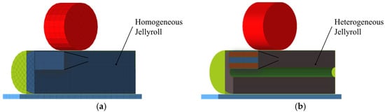
Figure 3.
Schematization of homogeneous jellyroll model. (a) Homogeneous jellyroll section. (b) Heterogeneous jellyroll section.
This work aims to create accurate yet simplified homogeneous jellyroll material characteristics that can replicate the results of the detailed model within an acceptable accuracy range, based on the root mean square error (RMSE).
3.2. Homogeneous Material Model
The material model utilized by the authors is largely adopted in the literature and is derived from [22]:
In this equation, A and B represent two parameters which would need to be calibrated through the experimental campaign on a stack of jellyroll material. In this work, the authors calibrated the parameters adopting a full factorial approach, simulating all the possible combinations of A and B within a predefined range:
A = [1000:1000:10,000]
B = [1:1:5]
The simulation was automatically run using a script that generated all the key-files needed for the LS-Dyna environment.
The simulations were run for the indentation and impact tests, considering the same range, for 50 simulations each. The time required for a single simulation was less than 1 min, drastically reduced compared to the 20 h of the heterogeneous model. The number of elements of the homogeneous model was reduced to ~103, which resulted in a 3-order reduction. Figure 4 shows a comparison between the simulation results of the homogeneous model (left) and the heterogeneous model (right) with displacement contours. The homogeneous model shows a smooth, averaged displacement distribution due to its simplified approach, while the heterogeneous model captures the detailed layer-by-layer deformation of the jellyroll, resulting in a more distinct contour variation. This highlights the increased resolution of local effects in the latter model.
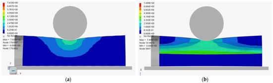
Figure 4.
Comparison of two proposed models: (a) homogeneous model; (b) heterogeneous model.
4. Simulation Results
In order to evaluate the simulation results, two output parameters were defined, as shown in Figure 5:
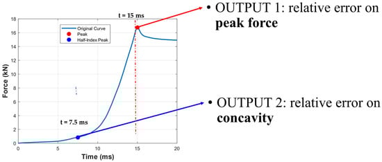
Figure 5.
Simulation output parameters.
- Peak force: This is the relative error on the peak vertical force.
- Concavity: This is the relative error on the vertical force considering a point halfway to the peak force. This parameter was conventionally called concavity by the authors, even if it is not a proper concavity but works as an indicator for the lower part of the curve, characterized by lower forces and displacements.
For each simulation, A and B’s influence and interaction with the results were evaluated to understand the best range of A and B so that a more refined study could investigate the value of best fit with an even greater degree of accuracy.
The results are shown in Figure 6 and Figure 7. For both the indentation (Figure 6) and impact (Figure 7) tests, the first outcome is that B has a greater influence on the relative error for concavity, whereas A affects the peak the most. The bottom-left plot shows a significant variation in the relative error on the peak as parameter A increases. The negative, non-linear trend indicates a strong sensitivity of the peak to A. The top-right plot illustrates how concavity values are primarily influenced by parameter B. The relative error on concavity appears less sensitive compared to A, with the curves showing convergence at specific B values, therefore suggesting a stability region. A further analysis of parameter interactions could help identify optimal configurations for A and B.

Figure 6.
A comparison of the two output parameters in the indentation test: (a) peak force; (b) concavity.
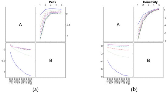
Figure 7.
A comparison of the two output parameters in the impact test: (a) peak force; (b) concavity.
Best Fit for Jellyroll Material: Single Model
The main output of this research work is the development of a material model that can be used in a finite element model of a battery pack. Once the influence of the two parameters was understood, the best fit for each test case was analyzed based on the RMSE evaluation. In Table 3, some of the RMSE values of the simulations are shown. The best RMSE values obtained were in simulations R039 and R049 for impact and indentation, respectively. The response in terms of vertical displacement for the impact test is visible in Figure 8, where the benchmark curve (in orange) is plotted.
Table 3.
Some of the RMSE values of the simulations in both test cases. The red ones are the best fits in terms of the RMSE for each test.
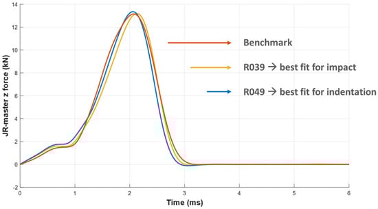
Figure 8.
Best-fit curves for the two tests, applied to the impact test simulation.
Moreover, if the sum of the RMSE for the two simulations for all the runs (Equation (2)) is evaluated, the minimum RMSE sum is on R039, which is the best fit for the indentation test and works well for the impact test (yellow curve). Material characteristics in terms of the A and B parameters can be used to simulate both indentation and impact.
where N = number of simulation runs.
In conclusion, considering the results obtained, the authors decided to employ the features of R049 in homogeneous models. In addition, the results highlighted that homogeneous models are potentially a solution that can effectively replace the use of detailed models.
5. Conclusions
Simulations play a crucial role in predicting and reducing the risk of thermal runaway during crush testing. An accurate yet simplified model of the battery cell, known as the homogeneous model, is needed to simulate an entire battery pack effectively.
The authors introduced a homogenization process using a full factorial approach to simulation, which generated a best-fit curve for the battery’s response. For validation, they compared the simplified homogeneous model to a detailed heterogeneous model they had previously developed. It was found that a single material model can be used in both test scenarios (indentation and impact).
Therefore, in this paper, a unified material characteristic was proposed. It can be applied across multiple test cases, eliminating the need for a specific material for each test.
This model represents a significant step toward future advancements in battery pack modelling.
Author Contributions
Conceptualization, A.K. and D.B.; methodology, A.K. and D.B.; software, A.K. and D.B.; validation, A.K., D.B. and M.D.; formal analysis, L.B., N.B. and A.K.; investigation, A.K.; resources, M.D. and A.K.; data curation, A.K.; writing—original draft preparation, A.K.; writing—review and editing, A.K., D.B., L.B., L.P. and M.D.; visualization, A.K.; supervision, M.D. and L.P.; project administration, M.D.; funding acquisition, M.D. All authors have read and agreed to the published version of the manuscript.
Funding
This research was funded by the European Union within the project AccCellBaT Horizon Europe (Grant No. 101103628 https://acccellbat.eu/ accessed on 10 January 2025). The views and opinions expressed are, however, those of the authors only and do not necessarily reflect those of the European Union. Neither the European Union nor the granting authority can be held responsible for them.
Institutional Review Board Statement
Not applicable.
Informed Consent Statement
Not applicable.
Data Availability Statement
The dataset can be made available on request from the authors.
Conflicts of Interest
The authors declare no conflicts of interest.
References
- E, J.; Xiao, H.; Tian, S.; Huang, Y. A Comprehensive Review on Thermal Runaway Model of a Lithium-Ion Battery: Mechanism, Thermal, Mechanical, Propagation, Gas Venting and Combustion. Renew. Energy 2024, 229, 120762. [Google Scholar] [CrossRef]
- Zhang, G.; Wei, X.; Tang, X.; Zhu, J.; Chen, S.; Dai, H. Internal Short Circuit Mechanisms, Experimental Approaches and Detection Methods of Lithium-Ion Batteries for Electric Vehicles: A Review. Renew. Sustain. Energy Rev. 2021, 141, 110790. [Google Scholar] [CrossRef]
- Wierzbicki, T.; Sahraei, E. Homogenized Mechanical Properties for the Jellyroll of Cylindrical Lithium-Ion Cells. J. Power Sources 2013, 241, 467–476. [Google Scholar] [CrossRef]
- Huang, J.; Shen, W.; Lu, G. Mechanism of Failure Behaviour and Analysis of 18650 Lithium-Ion Battery under Dynamic Loadings. Eng. Fail. Anal. 2023, 153, 107588. [Google Scholar] [CrossRef]
- Ruiz, V.; Pfrang, A.; Kriston, A.; Omar, N.; Van Den Bossche, P.; Boon-Brett, L. A Review of International Abuse Testing Standards and Regulations for Lithium Ion Batteries in Electric and Hybrid Electric Vehicles. Renew. Sustain. Energy Rev. 2018, 81, 1427–1452. [Google Scholar] [CrossRef]
- J2464_202108; Electric and Hybrid Electric Vehicle Rechargeable Energy Storage System (RESS) Safety and Abuse Testing. Battery Safety Standards Committee SAE International: Warrendale, PA, USA, 2021. [CrossRef]
- J2929A (WIP); Safety Standard for Electric and Hybrid Vehicle Propulsion Battery Systems Utilizing Lithium-Based Rechargeable Cells. SAE International: Warrendale, PA, USA, 2022. Available online: https://www.sae.org/standards/content/j2929/ (accessed on 13 February 2025).
- IEC 62660-3:2022; Secondary Lithium-Ion Cells for the Propulsion of Electric Road Vehicles—Part 3: Safety Requirements. International Electrotechnical Commission: Geneva, Switzerland, 2022. Available online: https://webstore.iec.ch/en/publication/65084 (accessed on 13 February 2025).
- ISO 12405-4:2018(en); Electrically Propelled Road Vehicles—Test Specification for Lithium-Ion Traction Battery Packs and Systems—Part 4: Performance Testing. ISO: Geneva, Switzerland, 2018. Available online: https://www.iso.org/obp/ui/en/#iso:std:iso:12405:-4:ed-1:v1:en (accessed on 13 February 2025).
- ISO 6469-1:2019; Electrically Propelled Road Vehicles—Safety Specifications—Part 1: Rechargeable Energy Storage System (RESS). ISO: Geneva, Switzerland, 2019. Available online: https://www.iso.org/standard/68665.html (accessed on 13 February 2025).
- United Nations Economic Commission for Europe. Recommendations on the Transport of Dangerous Goods: Model Regulations—Twenty-Third Revised Edition; United Nations Economic Commission for Europe: Geneva, Switzerland, 2023; ISBN 978-92-1-001905-7. [Google Scholar]
- Regulation No 100 of the Economic Commission for Europe of the United Nations (UNECE)—Uniform Provisions Concerning the Approval of Vehicles with Regard to Specific Requirements for the Electric Power Train [2015/505]. Off. J. Eur. Union 2015, L 87, 1–64.
- UL 2580|UL Standards & Engagement|UL Standard. Available online: https://www.shopulstandards.com/ProductDetail.aspx?UniqueKey=36829 (accessed on 13 February 2025).
- Torres-Castro, L.; Lamb, J. United States Advanced Battery Consortium Battery Abuse Testing Manual for Electric and Hybrid Vehicle Applications; United States Battery Consortium (USABC): Albuquerque, NM, USA, 2022; No. SAND2022-0089R, 1838583, 702383. [Google Scholar]
- GB 38031-2020; Electric Vehicles Traction Battery Safety Requirements. Standardization Administration of China: Beijing, China, 2020. Available online: https://www.chinesestandard.net/PDF.aspx/GB38031-2020 (accessed on 13 February 2025).
- Pan, Z.; Li, W.; Xia, Y. Experiments and 3D Detailed Modeling for a Pouch Battery Cell under Impact Loading. J. Energy Storage 2020, 27, 101016. [Google Scholar] [CrossRef]
- Greve, L.; Fehrenbach, C. Mechanical Testing and Macro-Mechanical Finite Element Simulation of the Deformation, Fracture, and Short Circuit Initiation of Cylindrical Lithium Ion Battery Cells. J. Power Sources 2012, 214, 377–385. [Google Scholar] [CrossRef]
- Jantscher, K.; Breitfuß, C.; Miklau, M.; Ismail, K.; Dobusch, P. Virtual Detection of Mechanically Induced Short Circuits in a Cylindrical Lithium-Ion Battery Cell Based on Finite Element Simulation. Batteries 2021, 7, 79. [Google Scholar] [CrossRef]
- Liu, B.; Duan, X.; Yuan, C.; Wang, L.; Li, J.; Finegan, D.P.; Feng, B.; Xu, J. Quantifying and Modeling of Stress-Driven Short-Circuits in Lithium-Ion Batteries in Electrified Vehicles. J. Mater. Chem. A 2021, 9, 7102–7113. [Google Scholar] [CrossRef]
- Voyiadjis, G.Z.; Akbari, E.; Łuczak, B.; Sumelka, W. Towards Determining an Engineering Stress-Strain Curve and Damage of the Cylindrical Lithium-Ion Battery Using the Cylindrical Indentation Test. Batteries 2023, 9, 233. [Google Scholar] [CrossRef]
- Yuan, C.; Gao, X.; Wong, H.K.; Feng, B.; Xu, J. A Multiphysics Computational Framework for Cylindrical Battery Behavior upon Mechanical Loading Based on LS-DYNA. J. Electrochem. Soc. 2019, 166, A1160–A1169. [Google Scholar] [CrossRef]
- Sahraei, E.; Campbell, J.; Wierzbicki, T. Modeling and Short Circuit Detection of 18650 Li-Ion Cells under Mechanical Abuse Conditions. J. Power Sources 2012, 220, 360–372. [Google Scholar] [CrossRef]
- Pugi, L.; Barbani, D.; Kociu, A.; Delogu, M.; Berzi, L.; Baldanzini, N. Failure Prediction of Railway Battery Cells Under Large Deformations. In Proceedings of the Sixth International Conference on Railway Technology: Research, Development and Maintenance, Prague, Czech Republic, 1–5 September 2024; pp. 1–12. [Google Scholar]
- Heimes, H.H.; Kampker, A.; Lienemann, C.; Locke, M.; Offermanns, C.; Michaelis, S.; Rahimzei, E. Lithium-Ion Battery Cell Production Process; PEM der RWTH Aachen University DVMA: Aachen/Frankfurt am Main, Germany, 2018; ISBN 978-3-947920-03-7. [Google Scholar]
- Afraz, M.V.; Ali Mohammadi, Z.; Karimi, G. A Novel Compact Thermal Management Model for Performance Evaluation of Tesla-like Lithium-Ion Battery Packs. Energy Convers. Manag. 2024, 300, 117927. [Google Scholar] [CrossRef]
Disclaimer/Publisher’s Note: The statements, opinions and data contained in all publications are solely those of the individual author(s) and contributor(s) and not of MDPI and/or the editor(s). MDPI and/or the editor(s) disclaim responsibility for any injury to people or property resulting from any ideas, methods, instructions or products referred to in the content. |
© 2025 by the authors. Licensee MDPI, Basel, Switzerland. This article is an open access article distributed under the terms and conditions of the Creative Commons Attribution (CC BY) license (https://creativecommons.org/licenses/by/4.0/).