Abstract
This paper presents the development of a full turbine model and subsequent aero-servo-elastic simulation of the IEA 15MW Reference Wind Turbine, such that aerodynamic loads can be obtained and then applied to a simplified drivetrain in Finite-Element Analysis. This approach facilitates the quantification, through a computationally efficient method, of airgap deflections within the direct-drive generator caused by the shaft eccentricity that arises from aerodynamic loads. Shaft deflections were found to be higher under rated wind speeds than higher operating speeds, and the aero-servo-elastic model presented here performs favourably compared to later-published models.
1. Introduction
The offshore wind industry continually pushes the boundaries of individual turbine size in order to capitalise on economies of scale [1], and the minimisation of maintenance requirements is prioritised. The use of direct-drive generators is one approach that aims to reduce O&M costs; however, inherent to their low-speed operation, these devices require immense electromagnetic torques to produce the same power output as their geared counterparts, necessitating large, heavy supporting structures. Significant efforts have been made in optimising these support structures to tolerate vast forces with minimal mass increase; however, as size envelopes continue to expand, improved modelling is necessary to properly inform endeavours in order to safely yield further optimisation.
In this paper, an aero-servo-elastic simulation of an onshore version of the IEC Class IB, IEA-15MW-RWT, was developed in the industry-standard software QBlade (CE v 2.0.5.1) [2]. By using wind field data generated in QBlade, the extraction of realistic aerodynamic blade-loading data was made possible, and these data were subsequently applied to a simplified CAD model of the drivetrain within an uncoupled SolidWorks Simulation Finite-Element Analysis (FEA), in accordance with the process devised in [3]. Through this, the impact of shaft deflections arising from aerodynamic loading on the airgap stability of the direct-drive generator can be obtained and hence accounted for in the design process.
2. Methodology
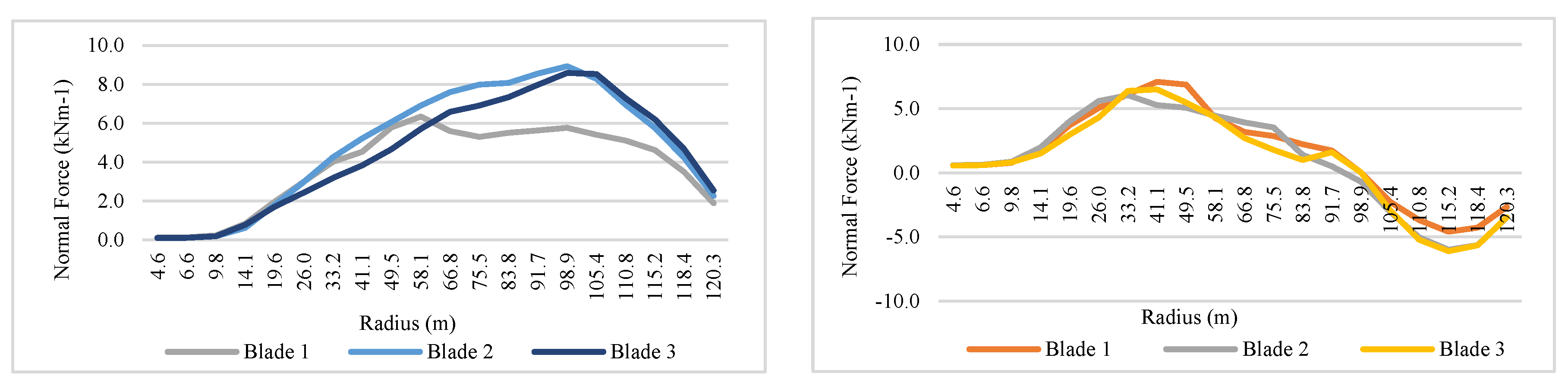
Using the available data from the IEA’s GitHub repository and the corresponding technical report [4,5], to suit the purposes of this work and with computational sustainability in mind, an onshore version of the IEA-15MW-RWT was developed. To define the turbine’s elastic behaviour in given weather conditions, the open-source DTU Wind Energy Controller [6] was used alongside a DISCON parameter file, modified according to data published for the IEA-15MW-RWT. QBlade uses NREL’s stochastic full-field turbulence simulator, TurbSim, to procedurally generate realistic wind fields for the environment in which the turbine operates across user-defined grids and mean wind speeds. The Kaimal turbulence model was used, and two main loading conditions were examined through the setup of their corresponding wind fields, ‘Rated’ and ‘High’, with mean hub-height speeds equal to the turbine’s rated speed of 10.6 ms−1, and 21 ms−1, respectively. Both wind fields had a width of 300 m, a height of 250 m, and reference and hub heights of 150 m. The normal force across the span of each blade experienced under ‘Rated’ and ‘High’ conditions (seen in Figure 1) was obtained from 10-min simulations with timestep sizes of 0.125 s, producing 4800 total steps.
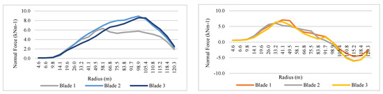
Figure 1.
Normal force exerted on blades at ‘Rated’ (left) and ‘High’ (right) wind speeds.
A simplified blade-and-driveshaft model was developed within SolidWorks to allow for an accurate and computationally efficient means to obtain shaft displacements. To represent the blades, shelled rectangular beams were created so that aerodynamic loads could be applied easily and transmitted to the shaft. These beams were equal in length to the blades, as defined in the definition document, and their widths and breadths were each taken as the blade’s average according to the CAD files. Full structural parameters of the simplified geometry are provided in Table 1, and the geometry can be seen in Figure 2, below.

Table 1.
Simplified structural model characteristics.
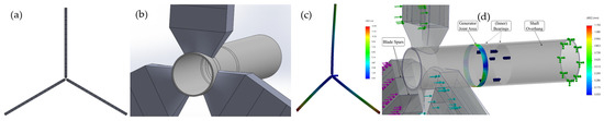
Figure 2.
Simplified drivetrain: (a) front view; (b) close view; (c) total deflection; (d) deflection at the shaft–generator joint.
Two continuous spars were added, with end caps on both the pressure and suction sides of the blades, as per the turbine definition document. For simplicity, the entire blade structure was assumed to be composed of E-Glass composite, as defined in the QBlade QFEM Structural Blade Design module.
A tubular shaft was created adhering to the dimensions provided in the definition document, with the shaft thickness, bearing widths, and distances between each bearing and the blade mounting position all set as defined in [5]; however, in contrast to the conical geometry mounting defined in [4], the shaft was instead given an overhang section and extended beyond Bearing 2, in observance of St. Venant’s Principle. Carbon steel SA216 (Type WCC) was used for the shaft. Although the bearings were not physically modelled, their effect on the structure was analysed using the Bearing Support Fixture function in two ways; ‘Rigid’ assumes that the bearings do not translate or deform, while ‘Flexible’ allows for axial displacement and deformation of the bearing face. Bearing stiffnesses vary with loading conditions and are complex to calculate; so, for simplicity, the axial and radial stiffnesses of each bearing were calculated by assuming that both bearings act as a hollow circular bar and have a stainless steel composition with roller lengths 75% of their total width, and internal clearances were not accounted for. Equations (1) and (2) were used to calculate the bearing axial and lateral bending stiffnesses, respectively.
3. Results
Mesh convergence was found with a global, blended, curvature-based mesh and maximum and minimum element sizes of 100 and 90 mm, respectively, resulting in a total of 7,663,984 nodes and 3,917,494 elements. The results for the ‘Rated’ and ‘High’ wind speeds are displayed in Table 2. Deflection arising under ‘High’ windspeeds with flexible bearings can be seen in Figure 2c.
Table 2.
Results of the structural analysis.
As is reflected in Figure 1, the results show that the blade undergoes higher levels of displacement under ‘Rated’ conditions than under ‘High’ conditions, as collective pitch is used to reduce the aerodynamic torque produced and maintain the maximum rotor speed above ‘Rated’ conditions, changing the effective lift profile. Two further simulations were conducted to explore a 10% increase and decrease from the ‘Rated’ load case, with their results likewise being given in Table 2, in order to better quantify the effects of increased loading on the generator. Maximum blade displacement was found to be within the worst-case tip deflection limit of 22.8 m specified in [5].
The IEA15-MW-RWT generator structure has an airgap diameter of 10.53 m, a nominal airgap length of 10.15 mm, and an airgap deformation limit of 2.03 mm to maintain airgap stability and avoid structural failure. By obtaining the shaft eccentricity through Equation (3), aerodynamic loads can be accounted for by reducing the airgap deformation limit accordingly. Assuming a maximum shaft–generator joint displacement of 1.312, the shaft eccentricity was found to be 12.9%, thereby reducing the effective airgap deformation limit to 1.78 mm.
To evaluate the computational efficiency of the model produced in QBlade in this work, comparative simulations were run on the subsequently published Monopile and VolturnUS-S variations under ‘Rated’ wind conditions. The VolturnUS-S RWT model is a floating platform developed as part of a collaboration between the University of Maine and the National Renewable Energy Laboratory [7]. The offshore variants were run under the same simulation parameters as those used for the simplified model, with no wave-field being generated; additionally, the Monopile model was run with the offshore environment deactivated. The total normal force on blade 1 of each model was obtained for every timestep, and then averaged. The CPU processing times for each simulation are shown in Table 3.
Table 3.
Computational efficiency comparison.
4. Discussion and Conclusions
Under identical conditions, the model developed in this paper produced aerodynamic loads within the range of 3.8% and 6.5% of those obtained from the Monopile and VolturnUS-S models, whilst reducing the CPU time by 42% and 52%, respectively. By running the Monopile variant with the onshore option enabled, the CPU time was reduced by only 7.7% on average, indicating that the added complexity of the substructure is predominantly responsible for increasing the computational expense. Although not significant, the simplified model produced higher normal forces than its counterparts. However, with the aim of better informing generator deformation limits in the optimisation process, it is reasonable to assert that overestimating the impact of aerodynamic loads provides a safe margin by which to optimise the direct-drive structure without fear of catastrophic failure; therefore, these results can be used to reliably inform subsequent analyses.
This paper presents the quantification of aerodynamic loading on the airgap stability of the IEA-15MW-RWT, with the intent of optimising the direct-drive generator structure accordingly. We intend to explore the incorporation of tangential loading in the structural simulation to provide further valuable insights and clarity on the airgap variance experienced by the generator as a result of aerodynamic loading on the blades, especially at high windspeeds where blade-loading profiles are more significantly affected by higher levels of blade pitch. The simplified blade structures deflect well within the tolerance specified in [5], and this work applies the methodology outlined in [3] to the IEA-15MW-RWT, representing a first in the literature for a turbine of this size; however the authors aim to further validate these findings and provide future results in subsequent publications.
Author Contributions
Conceptualisation, M.B. and P.J.-S.; methodology, M.B.; software, M.B.; validation, M.B. and P.J.-S.; formal analysis, M.B.; investigation, M.B.; resources, P.J.-S.; data curation, M.B.; writing—original draft preparation, M.B.; writing—review and editing, P.J.-S., N.S. and F.M.-S.; visualisation, M.B.; supervision, N.S., P.J.-S. and F.M.-S.; project administration, P.J.-S. and N.S. All authors have read and agreed to the published version of the manuscript.
Funding
This work was funded by Edinburgh Napier University under the SCEBE PhD Studentship.
Institutional Review Board Statement
Not applicable.
Informed Consent Statement
Not applicable.
Data Availability Statement
The original contributions presented in this study are included within the article; any further inquiries can be directed to the corresponding author.
Acknowledgments
The authors would like to acknowledge Julian Hammond-Miller of The Timken Company for his input and guidance on calculating bearing stiffnesses for use in this model.
Conflicts of Interest
The authors declare no conflicts of interest.
References
- Kaiser, M.J.; Snyder, B.F. Offshore Wind Energy Cost Modeling; Springer: London, UK, 2012; ISBN 9781608054220. [Google Scholar]
- Marten, D.; Saverin, J.; Perez-Becker, S.; Behrens de Luna, R. QBlade CE 2023 (v 2.0.6.4). Available online: https://qblade.org/ (accessed on 10 April 2023).
- Szatkowski, S.; Jaen-Sola, P.; Oterkus, E. An Efficient Computational Analysis and Modelling of Transferred Aerodynamic Loading on Direct-Drive System of 5 MW Wind Turbine and Results Driven Optimisation for a Sustainable Generator Structure. Sustainability 2024, 16, 545. [Google Scholar] [CrossRef]
- Gaertner, E.; Rinker, J.; Sethuraman, L.; Zahle, F.; Anderson, B.; Barter, G.; Abbas, N.; Meng, F.; Bortolotti, P.; Skrzypinski, W.; et al. IEAWindTask37/IEA-15-240-RWT: 15MW Reference Wind Turbine Repository. Available online: https://github.com/IEAWindTask37/IEA-15-240-RWT (accessed on 10 April 2023).
- Gaertner, E.; Rinker, J.; Sethuraman, L.; Zahle, F.; Anderson, B.; Barter, G.; Abbas, N.; Meng, F.; Bortolotti, P.; Skrzypinski, W.; et al. Definition of the IEA 15 MW Offshore Reference Wind Turbine; Golden, CO, USA, 2020. Available online: https://www.nrel.gov/docs/fy20osti/75698.pdf (accessed on 10 April 2023).
- Hansen, M.H.; Henriksen, L.C. Basic DTU Wind Energy Controller; DTU Wind Energy: Roskilde, Denmark, 2013; ISBN 9788792896278. [Google Scholar]
- Allen, C.; Viselli, A.; Dagher, H.; Goupee, A.; Gaertner, E.; Abbas, N.; Hall, M.; Barter, G. Definition of the UMaine VolturnUS-S Reference Platform Developed for the IEA Wind 15-Megawatt Offshore Reference Wind Turbine; Technical Report; U.S. Department of Energy: Oak Ridge, TN, USA, 2020. [Google Scholar] [CrossRef]

Disclaimer/Publisher’s Note: The statements, opinions and data contained in all publications are solely those of the individual author(s) and contributor(s) and not of MDPI and/or the editor(s). MDPI and/or the editor(s) disclaim responsibility for any injury to people or property resulting from any ideas, methods, instructions or products referred to in the content. |
© 2024 by the authors. Licensee MDPI, Basel, Switzerland. This article is an open access article distributed under the terms and conditions of the Creative Commons Attribution (CC BY) license (https://creativecommons.org/licenses/by/4.0/).