Abstract
Recent advancements in additive manufacturing have facilitated the production of conformal cooling channels with greater ease and cost-effectiveness. Compared to typical channels that are straight-drilled, conformal cooling channels (CCCs) provide enhanced cooling efficacy in the context of the injection molding process. The main rationale behind this is that conformal cooling channels (CCCs) possess the ability to conform to the shape of a molded object, which is not possible with conventional channels. Carbon-carbon composites (CCCs) have the potential to mitigate thermal stresses and warpage, decrease cycle times, and achieve a more homogeneous temperature distribution. Traditional channels utilize a design technique that is more intricate in comparison to CCC. The utilization of computer-aided engineering (CAE) simulations is crucial in the development of a design that is both efficient and cost-effective. The primary objective of this paper is to assess the efficacy of two ANSYS modules in order to validate the obtained results. The two modules demonstrate similar outcomes when used with models with a fine mesh. Hence, it is crucial to take into account the purpose of the study and the intricacy of the computer-aided design (CAD) geometry in order to make an informed choice regarding the appropriate ANSYS module to utilize.
1. Introduction
The affordability and simplicity of conformal cooling channels (CCCs) have been enhanced due to the utilization of additive fabrication techniques. The cold injection molding technique employed by CCC exhibits exceptional characteristics. Mold that adheres to the principles of the three Cs: clarity, coherence, and conciseness. Cross-linked carbon composites (CCCs) have the capacity to mitigate both warpage and thermal strain. In 2005, Dimla et al. utilized the I-DEASTM Moldflow analysis technique to ascertain the most favorable route [1]. The evaluation of “part cooling time” was conducted for ABM Saifullah and SH Masood using the ANSYS thermal analysis modules [2]. In 2009, the aforementioned researchers conducted an evaluation of individual components and made a comparison between standard and quadratic CCC profiles utilizing MPI simulation modules [2]. According to the cited source [2], it was observed that conformal channels exhibited a cooling rate that was 38% faster compared to non-conformal channels. The researchers Gloinn et al. [3] employed ABS polymer as the molten substance and utilized cooling water to determine the temperature of the mold. The thermal influence of injection molding cooling channel design was explored by Moldflow Plastic Insight 3.1 in 2007. The concept of consistency in creative content design was created by authors. Wang et al. demonstrated the benefits of cooling circuits [4]. In 2017, Khan et al. employed AMI modules to assess several parameters like cooling times, total cycle times, volumetric contraction, and temperature changes of traditional, serial, parallel, and additive-parallel cooling channels. Regarding the topic of this work, a similar study, which presnts a method for design optimization in three-dimensional analysis, was already developed [5]. There is a considerable body of literature on the analysis of CCC (continuous-column chromatography). However, there is a noticeable scarcity of research focusing on the study of design parameters for CCC across various designs. This research investigates the process of cross-validating both modules and determining the appropriate meshing settings. This study presents a comparison between ANSYS Mechanical APDL 2D transient thermal analysis and ANSYS Steady State/Transient Thermal in Workbench.
2. Methods
2.1. CAD Models (Computer-Aided Design)
The CAD model for this project was created on the ANSYS Workbench and ANSYS Mechanical APDL 2020 R2. The three-dimensional geometry is comprised of eight circular cooling channels, a rectangular mold cavity, and a curved plate representing a component. The assembly is depicted in Figure 1. Table 1 provides an elucidation of the constituent elements of geometry.
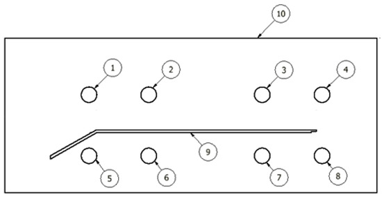
Figure 1.
Assembly drawing of the mold, showing dimensions in millimeters and component ID.

Table 1.
Components of the geometry used in the simulations and in the optimizations [5].
2.2. Materials
Water was employed in the cooling channels of the simulations, whereas polypropylene was utilized in the injection part. P20 steel was employed for the fabrication of the mold. Among the aforementioned components, it is postulated that only water exists in a liquid state, while both PP and steel are postulated to exist in solid states. Table 2 presents an overview of the properties and attributes of the material.
Table 2.
Properties of the materials used in this work [5].
The cooling channels, shown as round structures, were fabricated using liquid water. The injected section was fabricated using polypropylene (PP), while it is probable that the mold cavity was constructed using P20 steel. According to prevailing beliefs, steel is commonly acknowledged to exist predominantly in a solid form, whereas the remaining two substances exhibit properties that are more like those of liquids.
2.3. Numerical Procedure
The mesh employed in this study is a quadrilateral-free mesh. Despite the fact that both modules utilized identical mesh parameters, there is a notable disparity in the overall quantity of mesh pieces between Workbench and Mechanical APDL. The mesh seen in Figure 2a,b was generated utilizing Mechanical APDL and Workbench software, respectively.
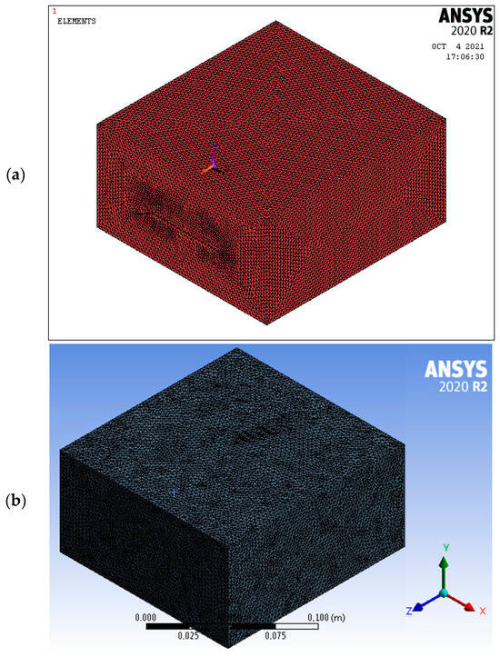
Figure 2.
Mesh in ANSYS Mechanical APDL (a) and in ANSYS Workbench (b).
The meshing parameters are shown in Table 3.
Table 3.
Meshing parameters.
The injected component is subjected to a temperature of 210 degrees Celsius. It is widely accepted that the water temperature within the cooling conduits remains constant at 40 degrees Celsius throughout. It is assumed that the ambient temperature is 23 degrees Celsius. One notable distinction between the two approaches lies in the fact that geometry is created internally within each module. The mesh settings that are kept identical result in meshes that exhibit noticeable variations in the number of elements. The reason for this disparity may be attributed to the fact that Workbench’s meshing capabilities offer a far wider range of options compared to those of Mechanical APDL. The default values are retained for all Workbench parameters that are not available in Mechanical APDL.
3. Results and Discussion
Figure 3 shows the maximum temperature Tmax in function of time for both the Mechanical APDL and the Workbench.
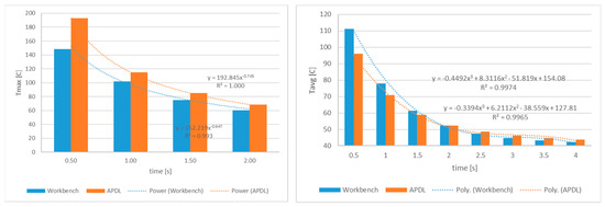
Figure 3.
Maximum temperature (left) and average temperature (right) in function of time for both the Mechanical APDL and the Workbench.
The findings of Workbench are quite close to those of Mechanical APDL, as shown in Figure 3. In most circumstances, Workbench shows maximum temperature readings that are somewhat higher than APDL. The errors regarding the results are shown in Figure 3 (right). Tavg values are shown in Figure 4. The errors were calculated using (1) the following equation:
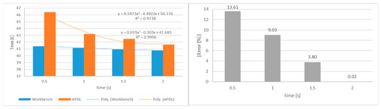
Figure 4.
Minimum temperature in function of time for both the Mechanical APDL and the Workbench (left) and error between the Mechanical APDL and the Workbench in function of time for average temperature (right).
In Figure 4 (left), it can be observed that Mechanical APDL outperforms Workbench in the majority of scenarios. However, the discrepancies between the two software components diminish with time. As shown in Figure 4 (right), the inaccuracy as a function of time corresponds to an exponential function for the average temperature Tavg and a third-degree polynomial function for the highest temperature Tmax. As seen in Figure 4 (left), the quadratic correlation is quite close to one. As seen in Figure 3 and Figure 4, the temperature distribution differs between the two software modules for all of the studied substeps. However, the temperature measurements in ANSYS Mechanical APDL and ANSYS Workbench are likely to be close. The temperature distribution clearly agrees better for t = 2 s than for t = 4 s and t = 2 s.
4. Conclusions
In the present scenario, it may be considered that a mesh with a diameter of 0.07 mm is sufficiently narrow to achieve the necessary level of precision. As illustrated in Figure 3, the development of four analytical models for temperature prediction over time involved the utilization of quadratic equations of the second degree. Despite diligent attempts, significant disparities exist in the module configurations of the two utilized software applications, hence impeding the feasibility of replicating simulation conditions with absolute precision, particularly regarding meshing characteristics. The mesh parameters and element type were identified as the most notable differentiating factors. As a result, it is possible to observe a discrepancy between the two modules when using coarse meshes. However, when using the finest mesh, a high level of agreement is observed. The discovered numerical inconsistencies can be mostly attributed to the differences in the meshing modules of the two software programs, namely in relation to the elements and the overall mesh structure. In subsequent times, there is the potential to integrate the differentiations between the two software systems by means of two independent equations. By utilizing these equations, it is possible to ascertain the necessity for additional mesh refinement.
Author Contributions
Conceptualization, H.M.S.; methodology, H.M.S.; software, H.M.S.; validation, H.M.S.; formal analysis, H.M.S.; investigation, H.M.S.; resources, H.M.S.; data curation, H.M.S.; writing—original draft preparation, H.M.S.; writing—review and editing, L.F., J.T.N. and H.L.R.; visualization, H.M.S.; supervision, A.J.P.; project administration, A.J.P.; funding acquisition, A.J.P. All authors have read and agreed to the published version of the manuscript.
Funding
This research was supported by the Research Grant number POCI-01-0247-FEDER-024516, co-funded by the European Regional Development Fund, by the Operational Program “Competitiveness and Internationalization”, in the scope of “Portugal 2020”.
Institutional Review Board Statement
Not applicable.
Informed Consent Statement
Not applicable.
Data Availability Statement
The datasets generated during and/or analyzed during the current study are available from the corresponding author on reasonable request.
Conflicts of Interest
The authors declare no conflicts of interest.
References
- Dimla, D.; Camilotto, M.; Miani, F. Design and optimisation of conformal cooling channels in injection molding tools. J. Mater. Process. Technol. 2005, 164, 1294–1300. [Google Scholar] [CrossRef]
- Saifullah, A.; Masood, S.; Sbarski, I. New cooling channel design for injection molding. In Proceedings of the World Congress on Engineering, London, UK, 1–3 July 2009. [Google Scholar]
- Gloinn, T.Ó.; Hayes, C.; Hanniffy, P.; Vaugh, K. FEA simulation of conformal cooling within injection molds. Int. J. Manuf. Res. 2007, 2, 162–170. [Google Scholar] [CrossRef]
- Wang, Y.; Yu, K.M.; Wang, C.C.; Zhang, Y. Automatic design of conformal cooling circuits for rapid tooling. Comput.-Aided Des. 2011, 43, 1001–1010. [Google Scholar] [CrossRef]
- Silva, H.M.; Noversa, J.T.; Fernandes, L.; Rodrigues, H.L.; Pontes, A.J. Design optimization of conformal cooling channels for injection molds: 3D transient heat transfer analysis. Mech. Adv. Mater. Struct. 2023. [Google Scholar] [CrossRef]
Disclaimer/Publisher’s Note: The statements, opinions and data contained in all publications are solely those of the individual author(s) and contributor(s) and not of MDPI and/or the editor(s). MDPI and/or the editor(s) disclaim responsibility for any injury to people or property resulting from any ideas, methods, instructions or products referred to in the content. |
© 2023 by the authors. Licensee MDPI, Basel, Switzerland. This article is an open access article distributed under the terms and conditions of the Creative Commons Attribution (CC BY) license (https://creativecommons.org/licenses/by/4.0/).