Abstract
In this research, a flexible inkjet-printed temperature sensor with in-house silver nanoparticles ink is presented and compared with the sensor printed with commercial silver nanoparticles ink. These sensors have an average width of 0.5 ± 0.04 mm in the latter and 0.5 ± 0.03 mm in the former. These serpentine-structure sensors were printed on polyethylene terephthalate (PET) substrate by using a Fujifilm Dimatix 2850 printer. The corresponding results indicating resistance have been recorded in the range of 30–100 °C to evaluate the sensor performance. The result of the studies showed that there was a linear relationship between the resistance and temperature for both ink types. The printed sensors developed using the in-house ink presented higher sensitivity, 0.1086 Ω/°C, compared to the commercial ink, which was 0.0543 Ω/°C. Therefore, the flexible inkjet-printed temperature sensor with the in-house silver nanoparticles ink is recommended for the large-scale productions and implementations.
1. Introduction
The emerging of IoT has radically impacted the advancement of printed electronics and fabrication technologies since the printing techniques have been industrialized. Today, paper-based electronics in the fields of flexible devices and wearables has gained great interest for utilization in a wide area of electronic systems because of its low costs in setup and methodology, as well as its eco-friendly fabrication technologies. Therefore, its development has become essential in order to co-exist with conventional silicon-based manufacturing systems to be deployed in IoT devices.
Among of the IoT technologies, the temperature sensor is one of the most widely employed in many fields, such as wearable sensors and logistics monitoring systems [1,2]. Most of the publications reported on temperature sensors as the resistive temperature detectors [3]. In order to fabricate a high-performance temperature sensor, the type and quality of the ink is one of the challenges of the printed electronics industry. For instance, the research in [4] and [5] have claimed their devices’ performances are excellent when using gold (Au) and copper (Cu) inks, respectively. However, the temperature of the paper substrate is not able to withstand both the required curing temperatures of the Au and Cu inks [6]. Compared to the Au and Cu inks, the silver nanoparticles ink (AgNPs) has been highly recommended due to the fact that AgNPs has low reactivity to air [7], minimal resistance to corrosion [8], a lower melting temperature [9] and lower costs [10]. Because of these, the commercial silver ink is dominating the market. However, the cost has become one of the greatest concerns of the industrial interest, as the cost of large-scale productions is high.
In this research, the low-cost and flexible in-house inkjet-printed temperature sensor with in-house silver nanoparticles ink is studied and compared to the sensor printed with commercial silver nanoparticles ink. The outcome of the research has shown that the performance in temperature sensing of the in-house sensor is comparable to the commercial sensor.
2. Materials and Methods
2.1. Temperature Sensor Design
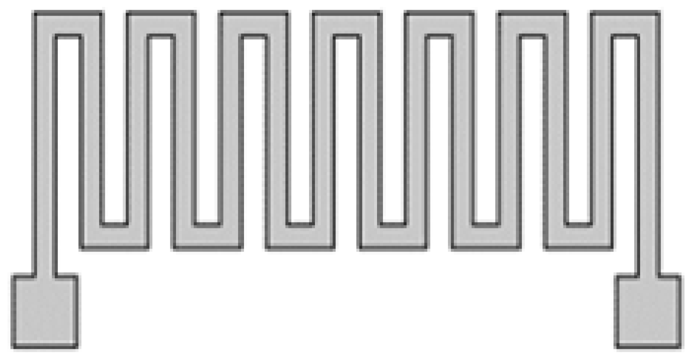
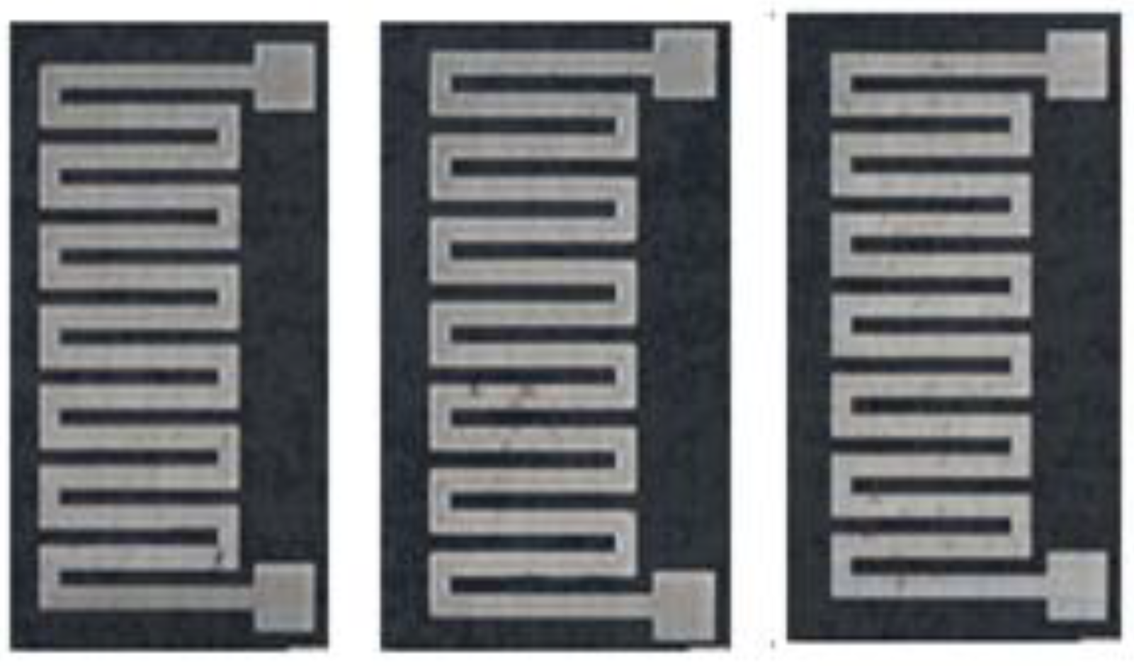
In this paper, a meandering shape-type temperature sensor is designed with the dimensions of 6.9 mm × 13.2 mm. The width of the sensor is 0.5 mm and the gap is 0.4 mm. The padding area is 1.5 mm × 1.5 mm. Figure 1 shows the design of a temperature sensor.
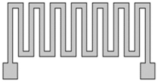
Figure 1.
Temperature sensor design
2.2. Flexible Substrate and Ink Preparation
The polyethylene terephthalate (PET) substrate used in this study was purchased from Elephantech Inc. with a thickness of 107 µm ± 32 µm. The PET comes in A4 size and can be cut into the desired size based on the application. This PET substrate was treated by the manufacturer and printed with the design directly.
In this study, there were two types of silver nanoparticles ink used to print the temperature sensor. The first one was the commercial silver nanoparticles ink purchased from Novacentrix (JS-B25HV). It was designed to print devices/circuits on coated substrates, including PET. Besides that, this ink was designed for the Dimatix Fujifilm printer and the printing waveform was provided.
Another type of silver nanoparticle ink used in this study was developed by our researcher. The idea of developing the in-house silver nanoparticles ink (in-house AgNPs) is to produce a low-cost silver nanoparticles ink and avoid the post-printing process (thermal cure). Table 1 shows the physical properties of in-house silver nanoparticles ink.

Table 1.
Physical properties for JS-B25HV and in-house AgNPs ink.
2.3. Inkjet Printing
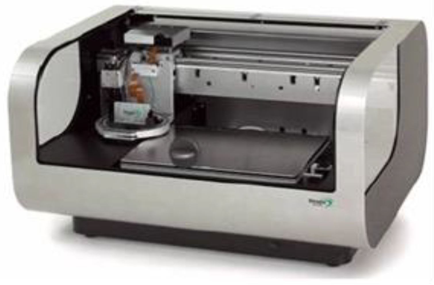
The temperature sensor was fabricated by the inkjet printing technique using a Fujifilm Dimatix printer-DMP 2850 (Figure 2). The DMP printer offers drop-on-demand (DOD) piezoelectric inkjet technology, which allows one to deposit fluid materials on a substrate. It allows users to modify the printer’s parameters in order to obtain the highest printing quality of products based on their fluids/inks. The silver nanoparticle ink is required to be sonicated around 15 min to avoid agglomeration between the particles. The fluid (~3 mL) was then put into the cartridge with a syringe, a needle and a 0.2 um filter. The filter was used to filter out the particles bigger than 0.2 um to prevent the nozzle head from clogging. It is recommended to keep the cartridge in the idle state for at least 30 min after filling.
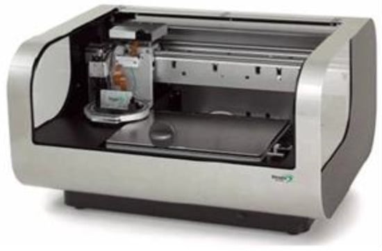
Figure 2.
DMP-2850 inkjet printer.
The meandering shape-type temperature sensor is designed and saved as the pattern file (.ptn) using the Pattern Editor (Bitmap images) on the DMP program. The number layers, drop spacing, image resolution and the leader bar were set properly according to the design specifications. The leader bar is a vertical line printed to the left of the pattern, for the purpose of pre-jet nozzles and keep the fluid drop velocity uniform to improve pattern quality.
In order to find the optimum deposition recipe, the printer parameters need to be adjusted based on the experimental outcome by trial-and-error. The printer parameters that were being investigated included substrate thickness, tickle control, plate/stage temperature, cartridge temperature, jetting voltage, meniscus setpoint, number of jets to use, and cartridge print height.
Table 2 shows the optimal printing parameters that were used for commercial ink (JS-B25HV), while Table 3 shows the optimal printing parameters used for the in-house ink.
Table 2.
Printing parameter for JS-B25HV.
Table 3.
Printing parameter for in-house ink.
2.4. Sensor Characterization
The geometrical characterization was performed using an optical microscope. The microscope was used to make sure the printed sensors matched the design and to monitor printed quality visually.
The temperature sensor was characterized by measuring the resistance between 30 °C and 100 °C with increments of 10 °C. The resistance values were measured using the FLUKE digital multi-meter.
3. Results and Discussion
3.1. Geometrical Characterization
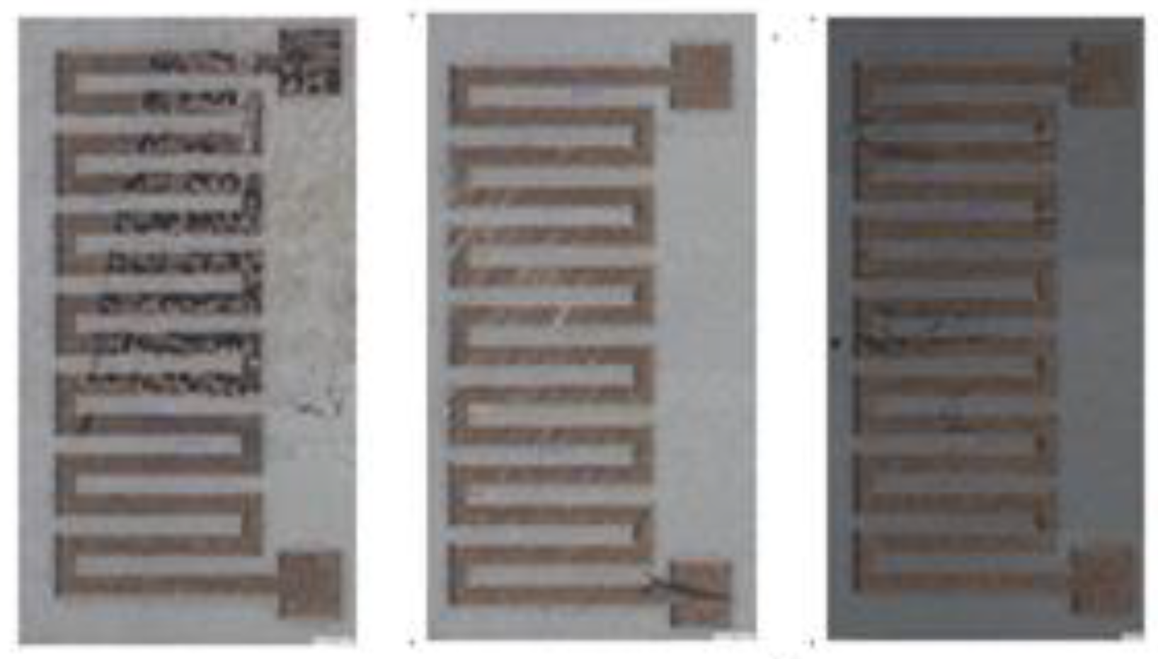
Before the electrical characterization, the printed sensors were observed using an Olympus microscope to investigate the surface morphology and uniformity. Figure 3 and Figure 4 show the microscope images for both ink types. Besides that, the dimension of the printed sensors is measured and compared to the design layout. Table 4 show the comparison between the design layout and the actual print. The inkjet printing methods present several adverse effects that cause inaccuracy in the printed structures. Based on the microscope results, the percentage errors for all the printed sensors are less than 10%, which is considered an acceptable result.
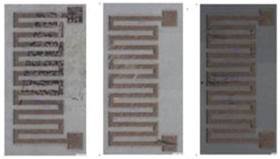
Figure 3.
Microscope image for JS-B25HV.
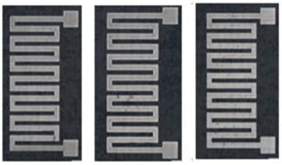
Figure 4.
Microscope image for in-house ink.
Table 4.
Comparison of the sensor dimension between design layout and actual printed sensor.
3.2. Electrical Characterazation
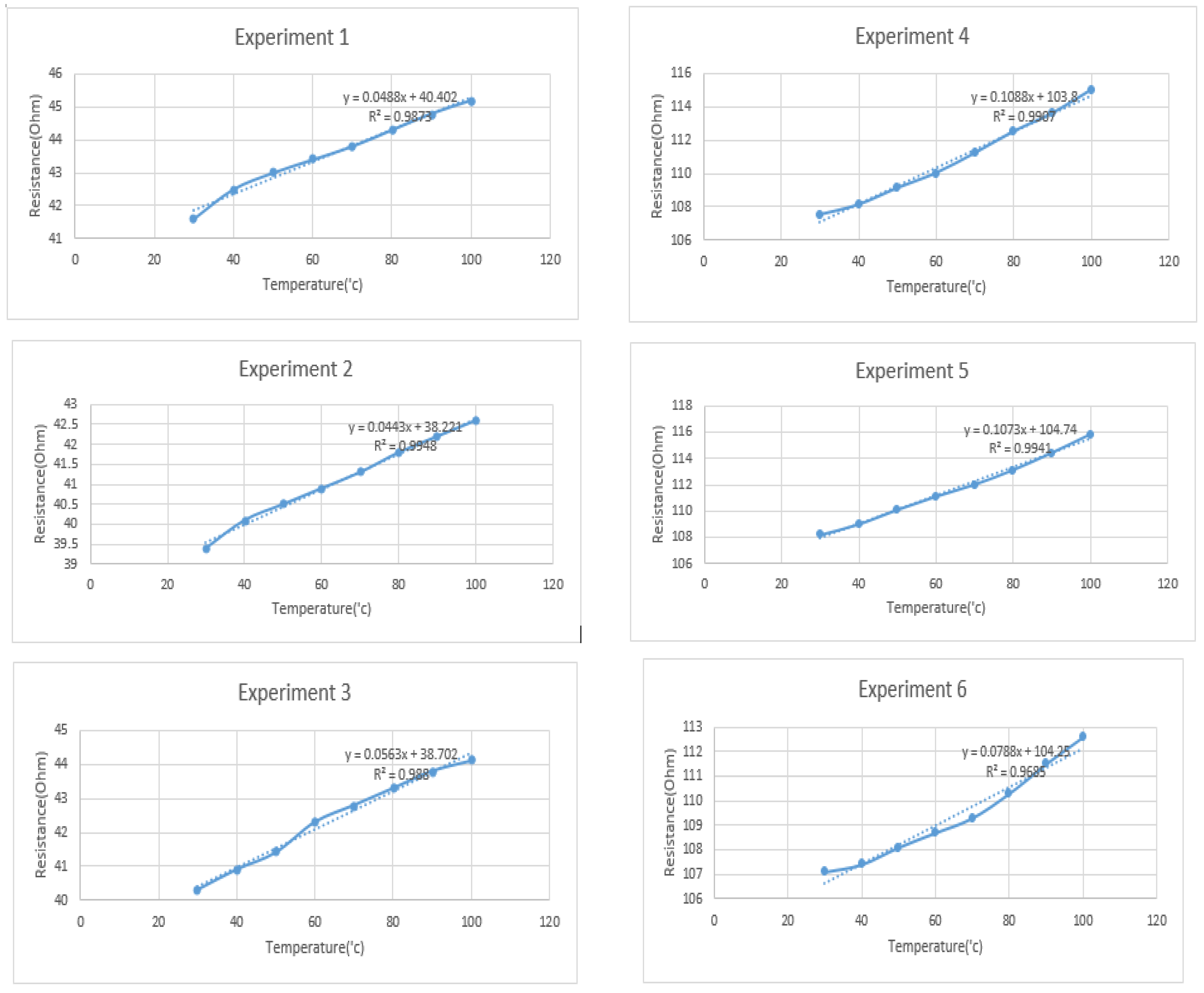
The performances of the temperature sensors were evaluated in the temperature range of 30 °C to 100 °C, with increments of 10 °C each time step. Figure 5 shows the relationship between resistance and temperature for both ink types. A total of six experiments were carried out. All of these showed a linear relationship between resistance and temperature.
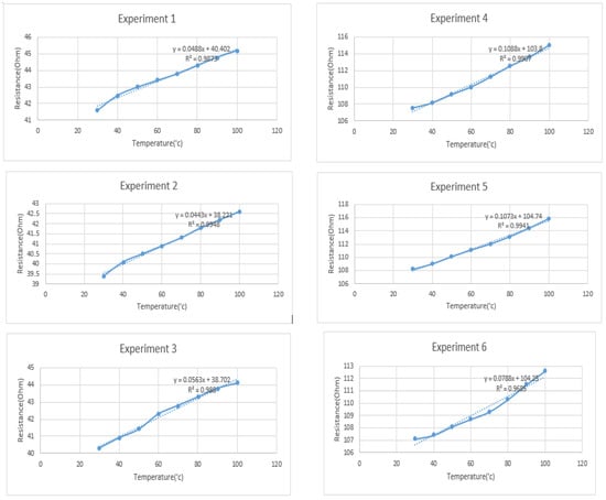
Figure 5.
Relationship between resistance and temperature for JS-B25HV (Experiement 1–3) and for In-house ink (Experiment 4–6).
The temperature coefficient of resistance (TCR) can be calculated by
where R100 and R30 denote the resistance value obtained at temperatures 100 °C and 30 °C, respectively, and ΔT is the change in temperature. The definition of TCR is the resistance change factor per degree Celsius of temperature change.
Besides that, the sensitivity (S) of the temperature sensors can be calculated by
where R100 and R30 denote the resistance values obtained at temperatures 100 °C and 30 °C, respectively, and ΔT is the change in temperature. The result in Table 5 show that the printed temperature sensor fabricated using the in-house ink obtained a higher-sensitivity performance compared to the commercial ink.
Table 5.
Sensitivity and TCR of printed temperature sensor.
4. Conclusions
The flexible temperature sensors were developed with an inkjet printer (DMP2850) using two types of ink: JS-B25HV and in-house silver nanoparticles ink. The performances of the printed sensors were evaluated by varying the temperature from 30 °C to 100 °C. The result show that the printed sensors have a linear relationship between resistance and temperature for both inks. The printed sensors developed using the in-house ink gave the higher sensitivity, which was 0.1086 Ω/°C, compared to the commercial ink. Therefore, the in-house ink is comparable to the commercial ink and has great potential industrial applicability.
Author Contributions
conceptualization, Q.J.L., H.F.H. and H.W.L.; methodology, Q.J.L. and A.S.A.A.; validation, Q.J.L., A.S.A.A. and M.W.L.; writing—original draft preparation, Q.J.L.; writing—review and editing, H.W.L.; visualization, Q.J.L.; supervision, H.W.L., H.F.H. and M.H.M.K.; funding acquisition, H.W.L. All authors have read and agreed to the published version of the manuscript.
Funding
This research was funded by ministry of Science, Technology and Innovation (MOSTI), grant number P0110020110122.
Acknowledgments
We would like to acknowledge the financial support provided by ministry of Science, Technology and Innovation (MOSTI) through the 11th Malaysia Plan development expenditure (DE) funding.
Conflicts of Interest
The authors declare no conflict of interest.
References
- Barmpakos, D.; Segkos, A.; Tsamis, C.; Kaltsas, G. A Disposable Inkjet-Printed Humidity and Temperature Sensor Fabricated on Paper. Proceedings 2018, 2, 977. [Google Scholar]
- Ali, S.; Khan, S.; Bermak, A. Inkjet-Printed Human Body Temperature Sensor for Wearable Electronics. IEEE Access 2019, 7, 163981–163987. [Google Scholar] [CrossRef]
- Dankoco, M.D.; Tesfay, G.Y.; Benevent, E.; Bendahan, M. Temperature sensor realized by inkjet printing process on flexible substrate. Mater. Sci. Eng. B 2016, 205, 1–5. [Google Scholar] [CrossRef]
- Cui, W.; Lu, W.; Zhang, Y.; Lin, G.; Wei, T.; Jiang, L. Gold nanoparticle ink suitable for electric-conductive pattern fabrication using in ink-jet printing technology. Colloids Surf. A Physicochem. Eng. Asp. 2010, 358, 35–41. [Google Scholar] [CrossRef]
- Lim, S.; Joyce, M.; Fleming, P.D.; Aijazi, A.T.; Atashbar, M. Inkjet Printing and Sintering of Nano-Copper Ink. J. Imaging Sci. Technol. 2013, 57, 1–7. [Google Scholar] [CrossRef]
- Saha, T.K.; Knaus, T.N.; Khosla, A. Investigation of Printing Properties on Paper Substrate. J. Electrochem. Soc. 2018, 165, B3163. [Google Scholar] [CrossRef]
- Öhlund, T.; Schuppert, A.; Andres, B.; Forsberg, S.; Andersson, H.; Schmidt, W.; Nilsson, H.-E.; Zhang, R.; Olin, H. Assisted sintering of silver nanoparticle inkjet ink on paper with active coatings. RSC Adv. 2015, 5, 64841–64849. [Google Scholar] [CrossRef]
- Wignes, F.L.; Glascoe, C.; Makar, G.; Karacolak, T.; Sekhar, P. A paper based 2-element antenna for WLAN MIMO applications fabricated using inkjet technology. Microw. Opt. Technol. Lett. 2017, 59, 2785–2790. [Google Scholar] [CrossRef]
- Hassan, A.; Ali, S.; Hassan, G.; Bae, J.; Lee, C.H. Inkjet-printed antenna on thin PET substrate for dual band Wi-Fi communications. Microsyst. Technol. 2016, 23, 3701–3709. [Google Scholar] [CrossRef]
- Huang, Q.; Shen, W.; Fang, X.; Chen, G.; Guo, J.; Xu, W.; Tan, R.; Song, W. Highly flexible and transparent film heaters based on polyimide films embedded with silver nanowires. RSC Adv. 2015, 5, 45836–45842. [Google Scholar] [CrossRef]
Publisher’s Note: MDPI stays neutral with regard to jurisdictional claims in published maps and institutional affiliations. |
© 2020 by the authors. Licensee MDPI, Basel, Switzerland. This article is an open access article distributed under the terms and conditions of the Creative Commons Attribution (CC BY) license (https://creativecommons.org/licenses/by/4.0/).