Abstract
Pipeline joint coating is key to maintaining the integrity and service life of oil and gas pipelines. This study presents a novel full-process automatic joint-coating system, comprising a modular design of a universal chassis and four operational modules: abrasive blasting, medium-frequency heating, primer spraying, and heat-shrink-tape wrapping. The innovation lies in its axial obstacle-crossing mechanism, automated opening/closing device, and circumferential rotation system, enabling semi-automated joint-coating operations with the potential for full automation in future iterations. Finite element simulations confirmed the structural strength and safety margins of critical components under operational loads. Experimental validation demonstrated that pre-heating to 120 °C via 5 kHz heating took only 2 min (versus 3 min at 4 kHz and over 5 min at 3 kHz) and that primer-spraying parameters (nozzle height/travel speed) produced uniform coating thickness above 400 µm. Adhesion tests at pipe temperatures above 200 °C and rolling speeds ≤ 16 mm/s consistently exceeded 100 N/cm, while speeds above 20 mm/s caused defects. The system therefore offers a reliable engineering solution for high-efficiency, reproducible pipeline joint-coating operations.
1. Introduction
Long-distance pipelines, welded from steel pipes, are the primary means of transporting natural gas, crude oil, and other energy products. To prevent soil-induced corrosion, their external surfaces are generally prefabricated with anti-corrosion coatings; however, the pipe ends remain uncoated for welding and require joint coating afterward. The reliability of joint coating is critical to maintaining pipeline integrity, yet traditional manual processes are prone to inconsistent quality (Figure 1), while existing mechanized systems suffer from low automation and limited efficiency [, , , , ]. To address these challenges, this study introduces an innovative design concept for Full-Process Automatic Anti-corrosion Joint-Coating Equipment.
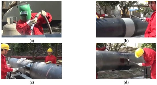
Figure 1.
Manual joint-coating procedures: (a) sandblasting; (b) pipe preheating; (c) primer application; and (d) installation and heating of the heat shrink tape.
In pipe-climbing robotics, Hunan University [] proposed an eight-wheel embracing configuration enabling 1.2 m/s high-speed motion but limited to pipe diameters of Φ508–1219 mm. To improve adaptability, Inner Mongolia University [, , ] developed a bionic inchworm robot with a telescopic joint, increasing axial mobility by 40%. Northeast Petroleum University [, ] designed the PGR-II gravity-locking device with a simple structure but poor obstacle-crossing ability due to its passive clamping mechanism. More recently, Harbin Institute of Technology [] introduced a permanent magnet adaptive adsorption system with dynamic gap adjustment, maintaining a stable 0.85 kN adsorption force on uneven 10 mm surfaces and providing new strategies for operation in complex conditions.
Research on mechanized joint-coating equipment remains limited both domestically and internationally. Hao Zhou et al. [] developed a mobile medium frequency heating device for heat-shrinkable-tape joint coating, enabling uniform heating, rapid temperature rise, and controlled temperature maintenance to resolve adhesive melting issues. Xinyu Lv et al. [] proposed a medium-frequency heating device for large-diameter pipelines. Changjiang Wang et al. [] designed a PLC-controlled automatic sandblasting system with a 600 mm rust removal width suitable for 1219 mm pipelines, featuring stable performance, high automation, and improved efficiency. Chao Jia et al. [] introduced an automatic rust-removal device for overhaul projects, achieving high efficiency and stable quality under terrain slopes below 15°. Changjiang Wang et al. [] further developed integrated devices, combining rust removal, medium-frequency heating, and infrared-assisted heating, forming a multifunctional system that covers surface treatment, primer heating, and heat-shrink-tape melting in a unified joint-coating process.
This paper proposes an integrated equipment architecture based on a ‘universal chassis and functional modules’ concept. By combining an axial obstacle-crossing mechanism, a circumferential positioning system, and a multifunctional rotating module, the system enables the continuous automation of key processes such as sandblasting and medium-frequency heating. A structural mechanics model was established, and ANSYS (version 2022R1) finite element simulations were conducted to verify the strength of critical components including the chassis, sliding bracket, and cam rocker, ensuring structural integrity under a total weight limit of 450 kg. The total weight limit of 450 kg is also determined to minimize the load acting on the pre-applied anti-corrosion layer, effectively avoiding potential damage to the original pipeline coating during operation. The proposed design overcomes the limitations of traditional joint-coating equipment, providing an intelligent and lightweight solution for pipeline anti-corrosion projects. This innovation not only extends pipeline service life but also enhances energy security, underscoring its significant engineering value.
Despite the progress reported in the above studies, most existing joint-coating systems remain limited to single-stage functions such as sandblasting, medium-frequency heating, or primer spraying, with manual intervention still required between process transitions. Few have achieved continuous operation covering the entire surface treatment to sealing workflow. Moreover, previous designs often lack standardized modular interfaces and have not undergone quantitative validation of the structural integrity or heating performance through combined simulation and experimentation.
In contrast, the present study introduces a modular, full-process joint-coating system that integrates four key modules—abrasive blasting, induction heating, primer spraying, and heat-shrink-tape wrapping—onto a universal chassis capable of axial obstacle crossing and circumferential rotation. The work further incorporates a coupled electromagnetic–thermal analysis verified by experimental data, demonstrating its adaptability and repeatability under actual field conditions. These features constitute the principal practical novelty and engineering significance of the proposed system relative to prior research.
2. Design of Equipment Structure
To address the common requirement of circumferential rotation in rust removal, primer spraying, and thermal joint sealing, a universal chassis was developed as a carrier for interchangeable modules. This modular design enables the flexible integration of sandblasting, heating, painting, and winding functions within a unified platform. The overall equipment design is suitable for 1219 mm pipelines, meeting the requirements of GB/T 51241-2017 “Pipeline External Anti-corrosion Joint Sealing Technical Specification” [].
2.1. Design of the Universal Chassis
The general structure of the automatic driving chassis is shown in Figure 2. It mainly includes the upper frame, support ring and internal gear ring, etc. The horizontal rudder wheel of the upper frame can complete the axial walking action. The obstacle-crossing electric push rod drives the supporting wheels of the frame to alternate lifting and lowering to complete the action of the heat-shrink tape crossing. The support ring completes the opening and closing action of the equipment. The guide wheels on it provide support for the rotation of the internal gear ring. The internal gear ring completes the rotational action in the circumferential direction under the drive of the driving gear.
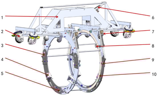
Figure 2.
Schematic diagram of the universal mobile chassis structure. 1—Upper frame; 2—horizontal steering wheel; 3—support ring; 4—positioning block; 5—quick-lock mechanism; 6—obstacle-crossing linear actuator; 7—opening–closing linear actuator; 8—dive gear; 9—guide wheel; and 10—internal ring gear.
2.1.1. Axial Obstacle Traversal Walking System
Regarding the problem of inter-layer failure caused by mechanical rolling before the thermal shrinkable tape solidifies in the pipeline joint-coating operation, this paper proposes a four-wheel group alternating the crossing mechanism based on the wheel drive. The obstacle-crossing working principle is shown in Figure 3. The black part is the joint-coating area. To the right is the direction of the equipment’s movement. Under the actuation of the electric push rod, the drive wheel sets 1 and 4 are lifted alternately to accomplish the obstacle-crossing motion and the axial walking action.
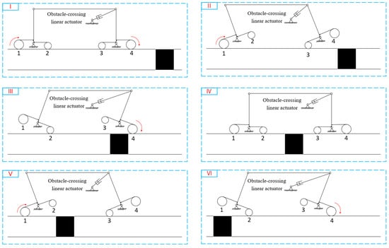
Figure 3.
Obstacle-crossing workflow diagram. (I) Preparation for crossing the coating-repair area. (II) Crossing Pose 1. (III) Crossing Pose 2. (IV) Completion of the first-half crossing. (V) Crossing Pose 1. (VI) Crossing Pose 2.
The force state of the drive wheel support frame is shown in Figure 4. Based on the force on the two-side support frames, the torque balance at points
and
can be obtained as follows.
where
are the forces exerted by the wheels on the support frame;
are the pulling forces of the pull rods on the support frame;
is the pushing force of the electric push rod on the support frame;
is the deflection angle of the support frame;
is the angle between the electric push rod and the pull rod; and
,
,
, and
are the distances from the force application points of
to the hinge points
and
. From this, the forces acting on the support frame can be obtained as the selection of electric push rod and the boundary conditions for the simulation.
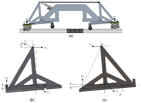
Figure 4.
Force analysis of the drive-wheel support frame: (a) obstacle-crossing state of the device; (b) force analysis of the left support frame; and (c) force analysis of the right support frame.
2.1.2. Design of the Equipment’s Opening and Closing Mechanism
The opening and closing mechanism is mainly composed of the support ring and the opening and closing electric push rod. The inner gear ring and the support ring are divided into three separate arc segments that can open and close synchronously to achieve this. When the opening and closing electric push rod retracts, it drives the two support rings to rise upwards, and the equipment only contacts the pipeline through the upper walking wheel group (as shown in Figure 5). In this state, the equipment can perform axial movement, cross-over pipe piers, and installation and disassembly of the equipment, etc.
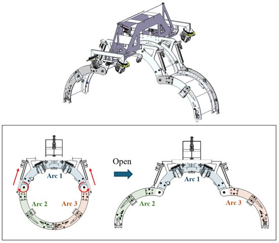
Figure 5.
Schematic diagram of device in open position.
To ensure structural alignment and operational stability, the mechanism adopts a circumferentially symmetric layout, in which two clamping supports and one electric push rod are arranged at 120° intervals. This configuration maintains precise coaxiality and effectively controls rotational runout, ensuring smooth engagement between the support ring and the inner gear ring while preventing misalignment or vibration during the opening–closing and spraying processes. In practical construction, pipeline ends are further aligned using an internal line-up clamp and trimmed with a beveling machine to ensure that the misalignment is less than 3 mm, thereby satisfying welding quality requirements. These measures effectively minimize the influence of coaxiality deviation, runout, and pipe ovality on radial clearance variation. High-precision machining and assembly processes are employed to maintain the coaxiality deviation within 0.5 mm and the rotational runout below 0.3 mm. The ovality of the clamping interface was limited to less than 1.0%, ensuring consistent contact and uniform coating thickness. Based on the above measures, the influence of coaxiality, rotational runout, and pipeline ovality on the variation in radial clearance is minimal. This has also been verified through experimental tests of the equipment.
2.1.3. Design of the Circumferential Rotation Mechanism
The circumferential rotating structure mainly consists of an inner gear ring and a driving gear. On both the inner and outer sides of the inner gear ring, guide wheels are evenly arranged to provide support for the rotation of the inner gear ring. Various functional modules can be installed on the rotating frame. The motor drives the driving gear to rotate the inner gear ring (as shown in Figure 6).

Figure 6.
Schematic diagram of the circumferential rotation mechanism.
The rotating frame needs to maintain a high-speed and stable rotation speed, as well as extremely high acceleration, to ensure the uniform and consistent thickness of primer spraying. The formula for calculating the driving torque of the rotating frame is as follows:
where
is the ring gear starting torque,
is the load moment of inertia,
is the load quality,
is the ring gear indexing circle radius, and
is the maximum radius of gear ring.
2.2. Structural Design of Functional Modules
2.2.1. Design of the Sandblasting and Rust Removal Module
The sandblasting–rust removal module is installed in the rotating frame through the adapter base plate. The servo motor drives the chain to make the spray gun shaft move back and forth. On both sides of the pipe’s circumference, a set of automatic rust removal modules is added. The modules rotate circumferentially, driven by the internal gear ring to complete the sandblasting operation. The installation position is shown in Figure 7. A monitoring scheme consistent with national standards and anchor pattern visual inspection methods is employed: surface cleanliness is visually assessed according to GB/T 8923.1-2011 (equivalent to ISO 8501-1) [, ], and surface profile (anchor pattern) measurement is carried out in accordance with ASTM D4417 [] via Method A (visual comparator) or Method C (replica tape). At least ten equally spaced locations around the circumference are tested; for the visual comparator, the segment most closely matching the profile is selected, and for the replica tape method, a micrometer reading is taken and adjusted for backing thickness. All recorded values are stored in the blasting log and inspection report to provide traceable documentation before primer spraying.
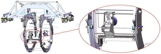
Figure 7.
Installation schematic of the automatic sandblasting equipment.
2.2.2. Design of the Mid-Frequency Heating Module
The intermediate-frequency heating coil is wound spirally on the outside of the pipeline. Special connectors are installed at the open position to complete the embedding of the spiral coil and the supporting ring’s opening structure, as shown in Figure 8.
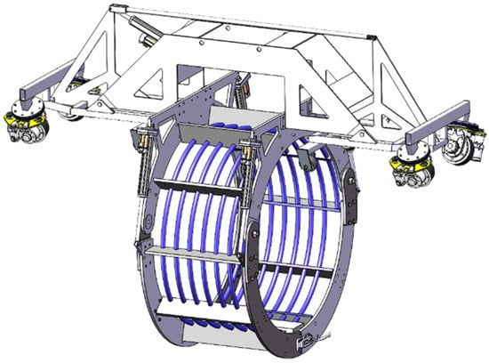
Figure 8.
Schematic diagram of the mid-frequency heating module.
The mid-frequency coil can be regarded as a spiral tube wrapped around the outside of the pipeline. The axial magnetic flux density generated by the coil is expressed as
where
is the number of turns per unit length,
is the alternating current, and
is the magnetic permeability of the medium. According to Faraday’s law of electromagnetic induction, the circumferentially induced electric field at a radius
inside the pipe can be written as
For an alternating current with frequency
and pipe conductivity
, the skin depth is given by
Under medium-frequency conditions, eddy currents are mainly confined within a surface layer of thickness
. The average dissipated power per unit length of the pipe can thus be approximated as
It should be pointed out that the derivation of Formula (8) is based on the following conditions:
- (1)
- The pipe wall thickness is much greater than the skin depth (i.e., the thin-wall approximation holds).
- (2)
- The pipe radius R is sufficiently larger than δ, so the local surface can be regarded as planar (curvature effects neglected).
- (3)
- The magnetic permeability μ is a linear constant, independent of magnetic field strength or temperature variation.
- (4)
- The electrical conductivity σ is uniform, and temperature-induced changes in conductivity are neglected during steady-state analysis
- (5)
- The induction heating coil and pipe wall geometry, as well as the spatial distribution of coil turns n, are idealized as uniform; there is no strong coupling at the coil edges, and end effects are assumed negligible.
Let the mass per unit length of the pipe be
(where
is the density and
is the cross-sectional area), and let the specific heat capacity be
. The convective heat-transfer area per unit length to the environment is
(for a thin-walled pipe, the outer surface area per unit
). Neglecting axial temperature gradients and assuming the radial temperature difference is small, the lumped parameter model can be applied:
Radiation can be linearized at medium to low temperatures (or for simplicity of analysis):
Then, the above equation is transformed into a first-order linear differential equation:
It follows from Equation (10) that
where the time constant is
The overall trend of the function shows that, in the early stage (
), the temperature rises approximately linearly. As the temperature increases, the heat dissipation becomes stronger, the heating rate gradually decreases, and the system eventually approaches a steady-state temperature.
2.2.3. Design of the Primer Spray Module
The automatic primer spraying module is shown in Figure 9. The equipment integrates the overlap isolation module, glue gun, and mobile spray head, etc. On the overlap area isolation module, there is a roll of isolation paper. As the rotating frame rotates, the isolation paper is wound around the overlap area of the pipeline anti-corrosion layer to prevent this area from being contaminated by the spray paint.
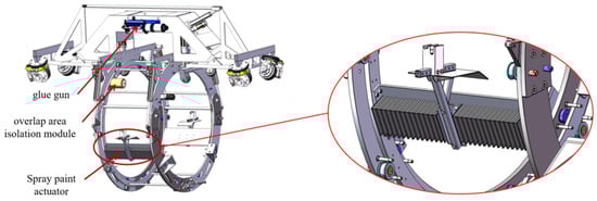
Figure 9.
Schematic diagram of the automated primer spray equipment.
2.2.4. Design of the Heat-Shrink-Tape Wrapping Module
The structure of the heat winding equipment is shown in Figure 10. It consists of a medium-frequency heating module, a press roller module, an infrared heating module, and a material roller module. The medium-frequency heating module heats the pipeline to bond the heat-shrink tape to the pipeline; the press roller module can lift or press the pipeline, and the surface of the press roller is designed in a stepped structure to adapt to the size changes at the weld and the pipeline anti-corrosion layer, providing compressive force for the heat-shrink tape to fully bond the pipe wall; the infrared heating module preheats the heat-shrink tape; and the material roller can pre-wrap the heat-shrink tape before construction, and can be quickly replaced during each pipe opening operation. The heat repair process is shown in Figure 11.
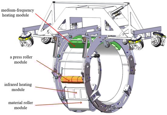
Figure 10.
Schematic diagram of the heat-shrink-tape wrapping module.
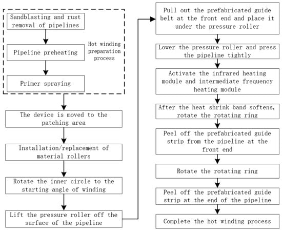
Figure 11.
Heat-shrink-tape wrapping process flow diagram.
Figure 12 shows the working principle diagram of hot winding and the axial cross-section of the pipeline. The red line in the figure represents the central axis of the pipeline. First, the gear ring rotates to the preset working angle. The leading end prefabricated guide band is pulled out from the material roller, and the handle on the press roller is operated to make it press the leading end prefabricated guide band. At this time, the end of the heat-shrinkable tape should be completely within the heating range of the infrared heating module. After preheating the end of the heat-shrinkable tape, the equipment rotates and drives the pressing roller to press the softened heat-shrinkable tape onto the outer wall of the pipeline. When the equipment rotates a full circle and the end of the heat shrinkable tape is also pressed onto the pipeline, the end prefabricated guide band is peeled off, and the hot winding operation is completed.
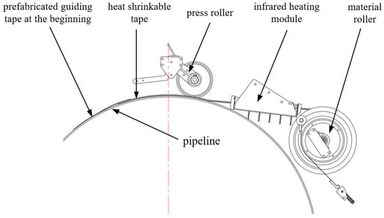
Figure 12.
Principle diagram of the heat-shrink-tape wrapping operation.
The pressing force of the press roller on the heat shrink belt is a key factor affecting the joint filling effect. When the press roller is located directly above the pipeline (Figure 13), the following equilibrium equation is used:
where
is the torsion spring torque,
is the support force of the pipeline on the press roller,
is the gravity of the press roller,
is the force exerted by the torsion spring, and
and
are the hinge point forces.
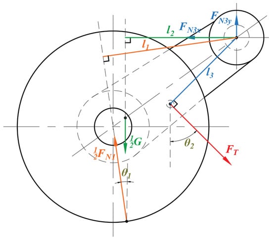
Figure 13.
Analysis of top compression force.
When the press roller is located directly below the pipeline (Figure 14), the following equilibrium equation is used:
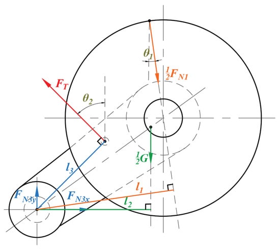
Figure 14.
Analysis of bottom compression force.
3. Simulation Analysis of Key Structural Components
Based on Table 1, after conducting the mesh-independence study and using the rotating frame as an example by comparing the five mesh cases (from coarse to fine), it can be observed that the peak stress gradually converges as the mesh is refined. When further refinement results in only very small changes and saturation is approached, this indicates the model results are essentially unaffected by mesh resolution and have entered a “mesh-independent” state. On this basis, we select a global mesh size of 5 mm, a mesh size of 3 mm for smaller structural surfaces, and further densification of the weld region by a factor of 2× (i.e., an effective size of approximately 1.5 mm or finer) as the mesh configuration for the final simulation. This scheme provides a reasonable balance between structural accuracy and computational cost.

Table 1.
Grid independence study.
3.1. Simulation Analysis of the Drive-Wheel Support Frame
The tetrahedral grid was used for the meshing of the rotating frame, with a grid size of 5 mm. The grid size at the smaller structural surfaces was set to 3 mm. The welding areas were treated with an increased mesh density level of two. The generated number of grid nodes was 1,045,535, and the number of elements was 391,309. The generated grid is shown in Figure 15. The connection between the support frame and the equipment frame is set as a cylindrical support, with the added load based on the results of the force analysis. The boundary conditions are set as shown in Figure 16. The structural material is set as 7075 aluminum alloy, with relevant mechanical parameters being the following: density of 2.77 g/cm3, Young’s modulus of 71 GPa, Poisson’s ratio of 0.33, and yield strength of 455 MPa [].
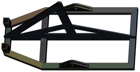
Figure 15.
Mesh partitioning of the drive-wheel support frame.
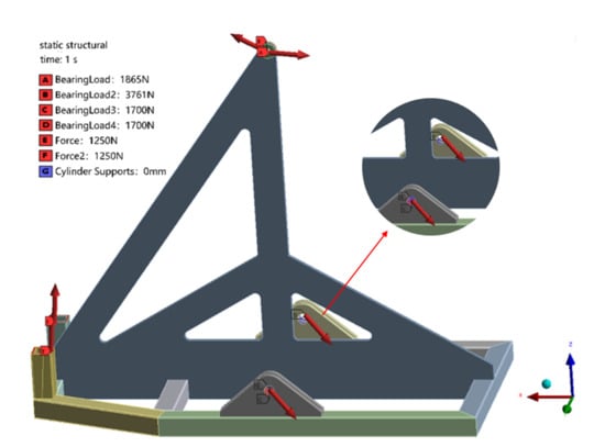
Figure 16.
Boundary conditions of the drive-wheel support frame.
The equivalent stress contour map obtained through simulation is shown in Figure 17. From the figure, it can be seen that the stress at the welding position of the square tube at the bottom of the support frame and the upper accessories is relatively high, with a stress magnitude of approximately 100 MPa. The maximum stress value is 120.45 MPa. The structural design meets the design standards and usage requirements and has a sufficient safety margin.
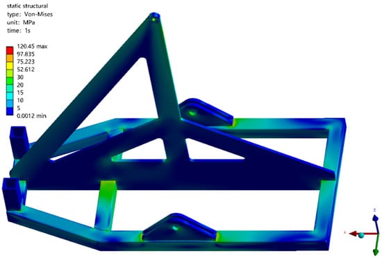
Figure 17.
Equivalent stress cloud diagram of the drive-wheel support frame.
3.2. Simulation Analysis of the Obstacle-Crossing Frame
The obstacle-crossing frame is connected to the aforementioned support frame and the obstacle electric push rod. Its force state forms a balanced force of equal magnitude but opposite direction with each point of the support frame. The boundary conditions are set as shown in Figure 18. A tetrahedral mesh is used for the meshing of the obstacle frame, with a mesh size of 5 mm. The welding areas are processed with an increased level of encryption, which is set at two. The generated number of mesh nodes is 1,535,892, and the number of mesh elements is 722,721, as shown in Figure 19. The material of the obstacle frame is also 7075 aluminum alloy, and the relevant mechanical parameters are the same as before. The equivalent stress cloud diagram of the obstacle frame simulation result is shown in Figure 20. The stress concentration in the sharp corners is not of reference value and can be ignored. The equivalent stress of the frame is basically below 250 MPa, and the structural design meets the design standards and usage requirements and a has sufficient safety margin.
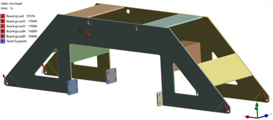
Figure 18.
Finite element analysis boundary conditions for the obstacle-crossing frame.
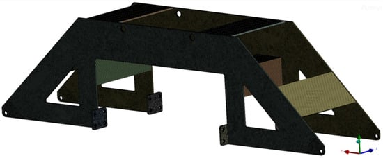
Figure 19.
Mesh partitioning of the obstacle-crossing frame.
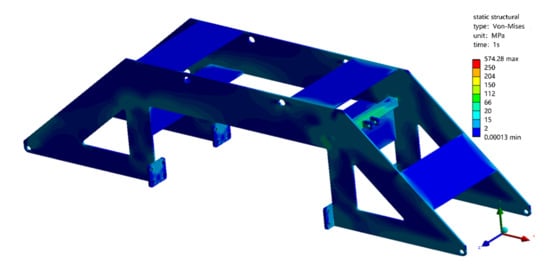
Figure 20.
Equivalent stress cloud diagram of the obstacle-crossing frame.
3.3. Simulation Analysis of the Rotary Frame
The gear ring on one side of the rotating frame is driven to rotation by the motor torque, overcoming the friction force. The non-gear ring side of the rotating frame is fixed, and an equivalent torque acting on the driving torque and friction force is applied to the other side. The rotating frame is meshed using a tetrahedral grid, with a grid size of 5 mm. The grid size at the smaller structural surfaces is set to 3 mm. The generated number of grid nodes is 2,994,145, and the number of elements is 2,328,482. The generated grid is shown in Figure 21.
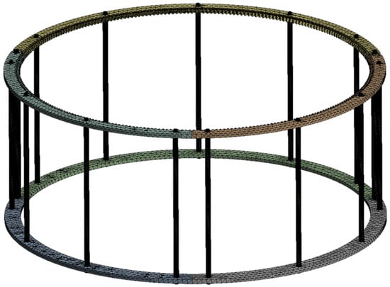
Figure 21.
Mesh partitioning of the rotary frame.
The structural material also adopts 7075 aluminum alloy, and the relevant mechanical parameters are the same as before. The deformation map is shown in Figure 22, and the equivalent stress map is shown in Figure 23. The simulation results can effectively identify the torque transmission path of the piston rod and the stress concentration area. By comparing the maximum deformation of the component with the yield limit of the material, the rationality of the design of the rotating frame structure and its torsional performance can be ultimately verified.
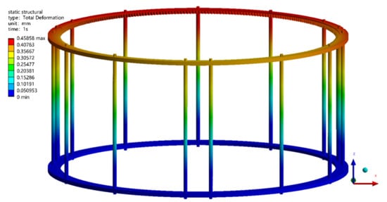
Figure 22.
Equivalent deformation cloud diagram of the rotary frame.
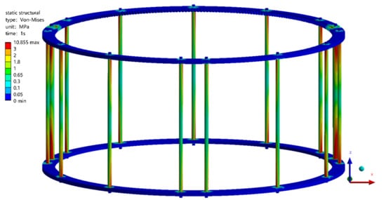
Figure 23.
Equivalent stress cloud diagram of the rotary frame.
4. Experimental Validation of the Joint-Coating Equipment
Ten anti-corrosion layers with a width of 300 mm were peeled off a pipeline as an experimental section, and tests were conducted on different functional modules on a universal chassis. Experimental research was conducted on the mid-frequency heating performance, primer spraying effect, and heat-shrink-tape winding effect, as shown in Figure 24. During the experiments, the equipment was operated under representative field conditions: it can travel on terrain with slopes up to 15°, suitable for straight long-distance pipelines. The system is powered by an AC 380 V source, stepped down to 220 V through the control cabinet to supply each module, with an air pressure of approximately 0.7 MPa and an ambient working temperature between –10 °C and 40 °C. These parameters, derived from multiple engineering applications, ensure stable operation and minimize any potential effect on the original pipeline structure and its anti-corrosion coating.
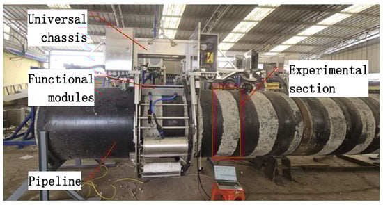
Figure 24.
The experimental rig of the joint-coating equipment.
4.1. Experiment of Mid-Frequency Heating Modules
Heating the pipeline at heating frequencies of 5 kHz, 4 kHz, and 3 kHz, respectively, four temperature sensors were arranged at 90 ° intervals around the circumference of the pipeline to collect temperature changes on the surface of the pipeline. The results are shown in Figure 25.
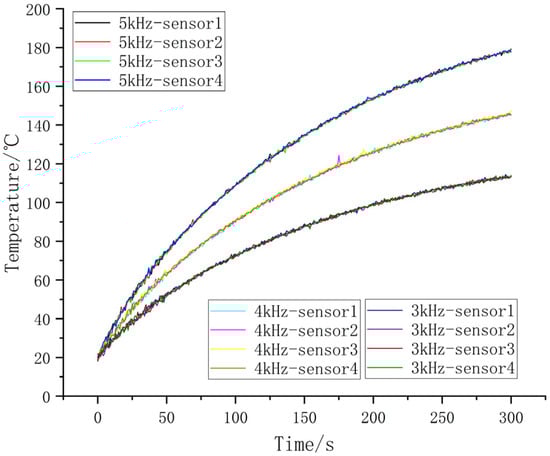
Figure 25.
Temperature variation in pipelines under different heating frequencies.
In the early stages, the heating rates of all three frequencies showed a rapid upward trend. This tendency is consistent with a higher thermal gradient between the surface of the pipeline and the surrounding environment, thereby reducing heat loss and enhancing energy accumulation. Among them, 5 kHz shows the steepest initial rise due to its higher electromagnetic power density, as supported by the theoretical relationship. The 3 kHz curve lags behind significantly, demonstrating the expected reduction in heating efficiency at lower frequencies. Notably, the 5 kHz case maintains the highest temperature rise rate across the entire heating period, whereas the 3 kHz case exhibits slower convergence. This divergence highlights the practical benefit of higher excitation frequencies in reducing heating duration for identical thermal loads. As the temperature increases, the heat dissipation from the pipe gradually intensifies, resulting in a progressive reduction in the heating rate and exhibiting typical first-order exponential behavior. For the preheating requirement of reaching 120 °C, the heating performance varies significantly with the excitation frequency. At 5 kHz, the target temperature can be achieved within 2 min, whereas at 4 kHz, 3 min are required to reach the same level. In contrast, at 3 kHz, the heating process exceeds 5 min before achieving the specified preheating temperature.
To further quantify the wall-heating behavior under different excitation frequencies, an exponential model was fitted to each of the three heating curves, expressed as
where
is the initial temperature,
is the asymptotic steady-state temperature, and
is the time constant representing the heating rate. The fitting results are
5 kHz:
4 kHz:
3 kHz:
Least-squares fitting was applied to the averaged sensor temperature data over the 0–300 s interval. The model reveals that, in the initial stage, the temperature rises exponentially, but as the balance between the heating input and heat loss is approached, the rise slows. This analytic form enables a quantitative comparison of heating efficiency across frequencies and provides a basis for parameter-identification within the electromagnetic–thermal dissipation model.
To extend the heating model to pipelines of other diameters and wall thicknesses, the following parameters can be adjusted: (1) the coil to pipe radius ratio, which determines magnetic coupling efficiency; (2) the number of turns per unit length, affecting power density; and (3) the effective wall thickness, which modifies the skin depth. By recalculating these parameters, the lumped parameter model Equations (8)–(13) can be directly applied to different pipe sizes, enabling the predictive optimization of heating time and temperature uniformity.
4.2. Experiment of Primer Spraying Modules
The effects of the nozzle to surface distance and the nozzle travel speed on the primer coating thickness were systematically investigated under constant air supply pressure. Specifically, experiments were conducted with nozzle heights of 200 mm, 225 mm, 250 mm, 275 mm, 300 mm, 325 mm, 350 mm, 375 mm, and 400 mm. For each height, the nozzle travel speeds were set to 40 mm/s, 50 mm/s, 60 mm/s, 70 mm/s, 80 mm/s, 90 mm/s, 100 mm/s, 110 mm/s, and 120 mm/s. The resulting coating thicknesses were measured using a calibrated coating thickness gauge to evaluate the influence of these parameters on film formation quality. The experimental device is shown in Figure 26.
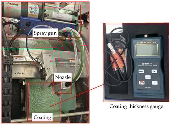
Figure 26.
The experiment device of coating thickness.
The experimental results are presented in Figure 27, where the colored surface represents the coating thickness corresponding to various nozzle travel speeds and nozzle to surface distances. The gray plane denotes the required coating thickness of 400 μm, and the intersection line between the two surfaces defines the critical boundary for the minimum acceptable coating thickness. As the nozzle distance increases, the spray dispersion becomes more pronounced, resulting in reduced deposition density and consequently thinner coatings. Similarly, higher nozzle speeds decrease the local residence time of the spray, further reducing coating thickness and intensifying the thickness gradient. This combined effect produces a nonlinear response surface, where coating thickness decreases sharply with increasing speed and distance. These experimental findings provide valuable guidance for parameter selection in primer spraying operations. To ensure both sufficient coating thickness and high spraying efficiency, the optimal parameter combinations should be chosen above and close to the intersection line.
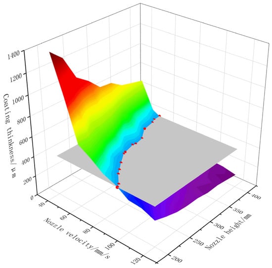
Figure 27.
The influence of nozzle speed and nozzle height on coating thickness.
4.3. Experiment of the Heat-Shrink-Tape Wrapping Module
The peel strength serves as a critical performance indicator reflecting the adhesive capability of heat-shrinkable tapes. After completing the field joint coating operation, a test specimen is prepared following a 24 h curing period by cutting a strip of the coating layer along the circumferential direction, with a width of approximately 20 mm and a length of at least 160 mm. One end of the strip is then clamped, and the coating layer is peeled vertically from the surface of the specimen at a constant velocity, ensuring uniform motion. The peeling force is continuously recorded during the process, as illustrated in Figure 28.
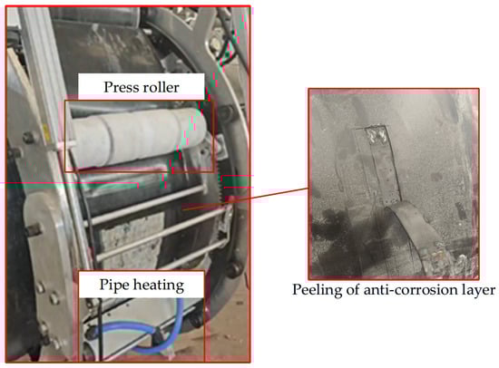
Figure 28.
The experiment of peeling strength.
The experimental results are presented in Figure 29, showing the variation in peel strength under different rolling speeds and pipe heating temperatures. The data demonstrate that increasing the pipe temperature and reducing the rolling speed both lead to a significant increase in peel strength. When the temperature exceeds 200 °C and the rolling speed is ≤16 mm/s, the peel strength consistently meets the requirement of being greater than 100 N/cm. However, at rolling speeds above 20 mm/s, the rapid rolling process may result in bubble entrapment, which can compromise the adhesion quality.
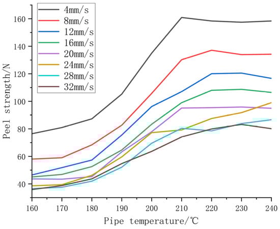
Figure 29.
The influence of rolling speed and pipe temperature on peeling strength.
5. Conclusions
The purpose of this paper is to develop a full-process automatic anti-corrosion joint-coating equipment to replace single mechanical anti-corrosion joint coating and manual joint coating. A pipeline heat-shrinkable tape anti-corrosion patching equipment that can perform pipeline obstacle walking and be driven by an electric motor has been designed. This equipment enables mechanized anti-corrosion patching to be independent of the reliance on hoisting machinery and can complete the spraying of sandblasting for rust removal, medium-frequency heating, primer spraying, and heat-shrinkable-tape winding in the anti-corrosion patching process. It solves many problems existing in the current pipeline heat-shrinkable-tape patching operations. The main conclusions of this paper are as follows.
- (1)
- A modular design integrating a universal chassis with interchangeable functional modules was proposed. The universal chassis incorporates axial obstacle-crossing, automated opening–closing, and circumferential rotation mechanisms, while the functional modules perform abrasive blasting, medium-frequency heating, primer spraying, and heat-shrink-tape wrapping. This design enables semi-automatic to near-automatic operation of the joint-coating process, significantly reducing manual intervention.
- (2)
- The structural integrity of critical components—including the rotating frame, sliding support, and cam rocker—was verified through finite element analysis. The results confirm that the system satisfies strength and safety requirements under operational conditions while maintaining a lightweight and robust configuration.
- (3)
- The experiments demonstrated that the system achieves uniform heating, controlled coating thickness, and adequate adhesion strength. For pipelines up to 1219 mm in diameter, the system meets industrial performance requirements and can be adapted for other sizes, such as 813 mm, ensuring broad applicability.
The all-process automated anti-corrosion patching equipment developed in this paper has a novel principle, a reliable structure, and is easy to achieve automatic control. It enables mechanized patching equipment to have the ability of axial pipeline walking and obstacle crossing and can complete the entire pipeline patching process. It realizes functions such as medium-frequency induction heating, automatic sandblasting rust removal, and automatic painting. It has high practical value and is of great significance for promoting the development of pipeline heat-shrinkable-tape patching equipment and the automation of patching operations.
Author Contributions
Conceptualization, C.W.; data curation, J.Y.; formal analysis, H.W.; methodology, J.Y.; resources, H.W.; software, G.J.; validation, G.J.; writing—original draft preparation, C.W.; writing—review and editing, S.Z. All authors have read and agreed to the published version of the manuscript.
Funding
This research received no external funding.
Data Availability Statement
The original contributions presented in this study are included in the article. Further inquiries can be directed to the corresponding authors.
Conflicts of Interest
Authors Changjiang Wang and Hehe Wang were employed by PipeChina Engineering Technology Innovation Co., Ltd. Authors Jianxin Yang and Guangpeng Ji were employed by PipeChina North Pipeline Company. The remaining authors declare that the research was conducted in the absence of any commercial or financial relationships that could be construed as a potential conflict of interest.
References
- Zhao, Y. CPP to Enhance China’s Pipeline Construction Powered by Technological Innovation and Supporting Important Projects. Pet. Sci. Technol. Forum 2011, 30, 17–19+68. [Google Scholar]
- Xie, Y.; Chu, X.; Ouyang, P.; Jiang, L.; Xing, J.; Yao, H.; Zayed, T. A mini review on coated pipes: Materials, manufacturing and anti-corrosion protection. Corros. Eng. Sci. Technol. 2025, 60, 217–230. [Google Scholar] [CrossRef]
- Shah, B.A.; Muthalif, A.G.A. A comprehensive review on corrosion management in oil and gas pipeline: Methods and technologies for corrosion prevention, inspection and monitoring. Anti-Corros. Methods Mater. 2025, 72, 681–701. [Google Scholar] [CrossRef]
- Yan, L.; Deng, W.; Wang, N.; Xue, X.; Hua, J.; Chen, Z. Anti-corrosion reinforcements using coating technologies—A review. Polymers 2022, 14, 4782. [Google Scholar] [CrossRef]
- Cheng, S.; Yuan, W. Corrosion mechanism and anticorrosion technology of oil and gas gathering and transportation pipeline. In IOP Conference Series: Earth and Environmental Science; IOP Publishing: Bristol, UK, 2021; Volume 859, p. 012115. [Google Scholar]
- Yang, Z.; Yu, J.; Wang, J.; Zhang, S. Lightweight Design of Cable Detection Climbing Device and Dynamic Performance Analysis. Mach. Des. Manuf. 2021, 10, 57–61. [Google Scholar]
- Yu, J.; Zhang, S.; Xiao, Q.; Luo, H.; Zhang, H. Design and Stability Analysis of Cable Inspection Robot’s Climbing Device. Mach. Des. Res. 2017, 33, 45–49. [Google Scholar]
- Zhang, S. The Design of Bridge Cable Inspection Robot's Climbing Device. Master’s Thesis, Hunan University, Changsha, China, 2014. [Google Scholar]
- Zhang, D. Structural Design of the High Voltage Transmission Line Tower Climbing Robots. J. Mech. Transm. 2015, 39, 93–96. [Google Scholar]
- Zhang, Z. The Research on The Mechanism of PGR-II Pipe Climbing Robot. Master’s Thesis, Northeast Petroleum University, Daqing, China, 2015. [Google Scholar]
- Zhang, Z.; He, F. Modeling and Simulation of PGR-II Pipe Climbing Robot. China Pet. Mach. 2016, 44, 106–110. [Google Scholar]
- Zhang, X. Research on Wall—Climbing Robot of Wheel—shaped Suspended Magnetic Adsorption. Master’s Thesis, Harbin Institute of Technology, Harbin, China, 2012. [Google Scholar]
- Zhou, H.; Liu, Q.; Liu, Y.; Jiang, Y.; Zhao, H.; Zhang, G.; Zhou, G. Application of Mobile Medium Frequency Heating Equipment in Field Joint Coating of Pipeline by Using Heat-shrinkable Tapes. Pet. Eng. Constr. 2015, 41, 75–78. [Google Scholar]
- Lu, Y.; An, Z.; Liu, Q.; Guo, M. Large-diameter Pipe Medium-Frequency Heating Equipment. Pipeline Tech. Equip. 2015, 6, 13–15. [Google Scholar] [CrossRef]
- Wang, C.; Zeng, H.; Zhao, Y.; Liu, R. Automatic Sand-Blasting Equipment Applied to 3rd West-East Natural Gas Pipeline Project. Fluid Mach. 2014, 42, 53–56. [Google Scholar]
- Jia, C. Design and Realization of Automatic Rust Removal Equipment for In-Service Pipeline Maintenance. Welded Pipe Tube 2020, 43, 53–56. [Google Scholar]
- Wang, C.; Zhang, F.; Zhang, H.; Liu, R.; Xu, M. Research on Integration of Joint Coating Equipment for Oil and Gas Pipelines. China Pet. Mach. 2022, 50, 142–149. [Google Scholar]
- GB/T 51241-2017; Ministry of Housing and Urban-Rural Development of the People’s Republic of China. Technical Code fer Field Joint Coatings of Pipeline. China Planning Press: Beijing, China, 2017.
- GB/T 8923.1-2011; Preparation of steel substrates before application of paints and related products—Visual assessment of surface cleanliness—Part 1: Rust grades and preparation grades of uncoated steel substrates and of steel substrates after overall removal of previous coatings. China Planning Press: Beijing, China, 2011.
- ISO 8501-1:2007; Preparation of steel substrates before application of paints and related products—Visual assessment of surface cleanliness—Part 1: Rust grades and preparation grades of uncoated steel substrates and of steel substrates after overall removal of previous coatings. International Organization for Standardization: Vernier, Switzerland, 2007.
- ASTM D4417-2003; Standard Test Methods for Field Measurement of Surface Profile of Blast Cleaned Steel. ASTM International: West Conshohocken, PA, USA, 2003.
- Wang, Z. 7075 The Approach to Holding Area Prediction of 7075 Aluminum Alloy Thick Plate for Pre-Stretching Processes. Master’s Thesis, Nanchang HangKong University, Nanchang, China, 2017. [Google Scholar]
Disclaimer/Publisher’s Note: The statements, opinions and data contained in all publications are solely those of the individual author(s) and contributor(s) and not of MDPI and/or the editor(s). MDPI and/or the editor(s) disclaim responsibility for any injury to people or property resulting from any ideas, methods, instructions or products referred to in the content. |
© 2025 by the authors. Licensee MDPI, Basel, Switzerland. This article is an open access article distributed under the terms and conditions of the Creative Commons Attribution (CC BY) license (https://creativecommons.org/licenses/by/4.0/).