Abstract
Fastenings are becoming increasingly important in modern building practice. A wide range of products cover for the great flexibility that they provide in a large variety of applications. In order to ensure the safe and economical use of the fastenings, a combined effort of manufacturing firms, practicing engineers and constructors, research organizations, and public authorities has led to the establishment of interrelated design standards, application guidance, and product approvals. It is however evident that failures, in fact even small defects, of fastenings can lead to disproportionate catastrophic events. In addition to these state-of-the-art documents, which reflect the most precise knowledge possible, a management of possible residual risks and hence causes of failure is also indispensable. Due to the great range of fastening systems with different dimensioning and assembly guidelines, load-bearing behaviour and areas of application, and the overall complexity of the subject, a coherent risk management procedure against structural risks can be very helpful in this respect. This article deals with the technical and load-bearing related risks of fastening technology in construction. The objective of the paper is to introduce fundamental concepts and significant risks met in the fastenings design specification and installation. Moreover, it provides a rating of the identified risks and it transfers recommendations for risk mitigation, based on semi-structured interviews with expert professionals who are active in the field. The results are accumulated in a dedicated risk register as a standard tool of the risk management process in civil engineering, which is the first of its kind in current scientific literature. The aim is to assist future practice and research by providing a basis for risk management considerations for fastenings, which moreover reflects actual risks indicated in the outcome of an industry survey.
1. Introduction
In the recent years, there have been repeated incidents of failure at fastening points with fatal consequences or considerable economic impact. Examples include the ceiling collapses of the Sasago Tunnel near Tokyo in Japan and in a tunnel section of the “Big Dig” Interstate Motorway Artery in Boston U.S.A.
The Boston incident involved very heavy reinforced concrete ceiling plates falling onto the roadway. On 10 July 2006 ceiling elements fell on a car on the roadway and injured the two passengers, one of whom died. According to the National Transportation Safety Board [1] and NASA [2], the main reason for the collapsing ceiling was the loss of the supporting bonded anchors due to failure of the mortar connection and consequent pull out. An epoxy resin mortar was used in these fastenings, which exhibited low resistance to creep under long-term tensile load. Further installation-related defects contributed to the reduction of the load-bearing resistance, which was discovered during the forensic inspection [1]. These included the incorrect method of preparing the borehole, insufficient mixing of the epoxy mortar, air pockets in the mortar due to improper filling of the drill hole, application of an excessive pre-stressing torque to the fastener, and clashes with concrete reinforcement during the drilling process. In addition to the personal injuries and litigation, there was an economic loss of around USD 54 million already in the first year of dismantling and repair works [2].
On 2 December 2012, ceiling slabs collapsed progressively over a length of 140 m in the Sasago Tunnel, killing nine people and injuring two more [3]. The main reason for the accident was attributed to the failure of the fastenings due to incorrect load assumptions and lack of structural redundancy in the designed load-bearing system [3]. Furthermore, installation defects leading to loss of strength were disclosed during the post-accident investigation. Three vehicles were crushed by the debris, and two of them caught fire, which aggravated the consequences of the situation because the ventilation system was integrated to the damaged ceiling.
Further incidents related to loss of fastenings of the suspended ceiling in the Uster public swimming hall in Switzerland (1985) [4,5], and a series of failure cases in public buildings and transport assets [6], as well as temporary work structures [7,8] in the United Kingdom. Meanwhile, field studies have shown that professionals dealing with fastenings may often lack technical knowledge and risk awareness on the topic [9,10].
Although the listed incidents are among the most serious in the construction industry, they are only a fraction of the total number of potential damages due to improper design, use and installation of fasteners. The effort of the industry to minimise the possibility of fastening failures is in the meantime evident in the establishment of modern design standards such as Eurocode 2—part 4 [11] with the associated product certification procedures, best practice guidance by technical authorities [12,13] and the introduction of special seminars for technicians (see for example [14] for requirements on horizontal to upwardly adhesive anchors installation). This also reflects the necessity that appropriate skillsets need to be present when it comes to using fastenings in construction, from the planning, the specification, and the installation through to the maintenance phase. Although the above initiatives may have already contributed to the safer use of fasteners, the fact that a building element with very small value can lead to events with very high consequences dictates that an appropriate fastening-specific risk management concept must be included and remain present in all phases of construction projects.
The present study attempts to propose a risk management concept with consideration of particularities related to fastenings in concrete and masonry. After this introduction, an overview of basic relevant background technical considerations and definitions on fastening technology is provided. This is followed by the risk methodology used for the investigated industry input. This input is the organised and tabulated in form of a fastenings-specific risk register, as a fundamental tool in risk management. The final section discusses the results in relation to the theoretical background and the conclusion includes a summary of main findings and recommendations for future research and the practical application of this investigation’s outcome. The risk identification, assessment, and mitigation, with focus on the load bearing safety of the systems, is derived from a survey based on interviews with practitioners in various sectors. In this way it was possible to assess as many risks as possible during the project development and to initiate preventive measures. This paper also presents a rare scientific discourse of different descriptions of practice-relevant risks caused by defects and errors in the design and construction practice is also a rare reference in published scientific discourse. The information provided is not viewed as exhaustive, nor does it intend to substitute engineering judgement, but it is expected that this transfer of knowledge will be of significant assistance in similar risk management exercises in practice and to the identification of future directions in research and industrial innovation.
2. Technical Considerations and Definitions in Fastenings Engineering
2.1. Load-Bearing Function of Fastening Systems
In the field of fastening technology, a large range of fastening products have been developed which act with different load-bearing characteristics. In general, three different main principles can be distinguished (see also Figure 1): Mechanical interlock, friction, and bond. Post-installed systems, such as undercut anchors and concrete screws, can be used to achieve an interlocking mechanism, which relies solely on compression contact between the anchor and concrete. Cast-in systems include shear connectors, transport anchors and anchor channels, and they use the same anchoring principle. In systems based on the load-bearing principle of friction, such as expansion anchors, the anchorage is created by lateral pressure from the anchor against the borehole wall. This is often done by a cone located at within a metal or plastic sleeve forming part of the anchor shaft. Bonded systems comprise a steel insert and a two-component mortar in a post-drilled hole, and they rely on a combination of adhesion and laterally generated friction between the fastening and the borehole. This connection most often requires the injection of mortar from cartridges or insertion through capsules into the hole. Finally, the direct fastening by means of setting bolts in concrete through impact should be mentioned as it gains popularity in non-structural but safety-critical applications [15]. In addition to the generally categorised fastening systems mentioned above, there are also special or hybrid applications. A more detailed presentation of fastening technology is given in [16].
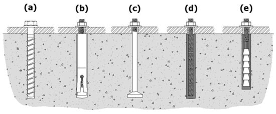
Figure 1.
Different anchor types, depending on the installation procedure: (a) concrete screw, (b) expansion anchor-sleeve type, (c) cast-in-place headed stud, (d) bonded anchor with threaded rod, (e) special bonded anchor (all pre-positioned systems).
2.2. Fastening Types and Assembly Configurations
With regard to the type of mounting and the associated sequence of assembly, a distinction can be made between pre-positioned and through-hole assemblies (see Figure 2). With prepositioning, the fastener is set ahead of the fixture to be attached, with the obvious demand for a very precise drilling and some tolerances in the attachment. Through-installation offers the possibility to first position the fixture and to drill and install the fasteners through holes in the attached component. In both cases, the fixture (e.g., steel plate) can stay at a distance of the substrate surface for a variety of construction reasons such as insulation or tolerance regulation, namely leading to a stand-off installation.
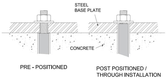
Figure 2.
Anchor installation configurations, dependent on logistic.
Depending on the structure-specific safety requirements, a fastening system is formed so that the loads are transferred into the anchoring substrate either via individual fasteners, which can also be formed as a group of fasteners, or with a multiple fastener-system in a redundant arrangement. In first case, failure or defect of a single anchor is directly translated to a system issue. In redundant fastening systems, the safety reserves of the system are accounted for in the design, and allowance is made for loss of individual elements without necessarily leading to loss of the system or excessive deformations. In case of a redundant multiple fastening system, the failure of individual anchors is compensated by the adjacent fastenings via the mounted fixture with several anchorage points. Therefore, apart from a minimum number of fastening points, an attachment with sufficient structural properties is required for the function of the system.
2.3. Anchorage Substrate Materials
In addition to the fastener itself, the anchorage substrate is a decisive factor for the anticipated structural performance, the stress that can be absorbed, and the technique or difficulty of installation. In the realm of fastening technology, the substrate can basically be differentiated between concrete, masonry, and lightweight construction materials. Depending on the existing anchorage substrate and the fastener to be used, the borehole should be drilled by appropriate configuration of drilling tools and equipment.
Due to its homogeneous, standardized composition and the possible specially aligned reinforcement, concrete can absorb the highest loads relevant to the design, and it can allow for a good balance between reliable and easy to plan installation projects. It is nevertheless indispensable to differentiate between cracked and non-cracked concrete, since cracked concrete has lower resistance regarding the fastening technology.
Masonry is an umbrella term for structures built by a multitude of different types of natural or artificial stone. Common types of masonry stone are solid bricks, perforated bricks, or natural stone blocks. Since only a small number of masonry stones are standardized, both the material properties and the geometry of the stones can vary greatly. For these reasons, it is often not possible to verify the actual loads that can be absorbed in masonry without testing and the permissible loads are generally lower than that of concrete.
Lightweight building materials have a low bulk density compared to normal concrete or natural stone, as they are made of lighter, more porous materials. In most cases, lightweight materials are used for non-load-bearing structures, but depending on the material, they may be also found in load-bearing function. Because of the use of lightweight materials for mostly non-structural applications, the fasteners for these do not require an exceptional load-bearing capacity and therefore often do not require a safety assessment.
2.4. The European Status in Technical Product Specification
Already a few decades ago, the ‘European Organisation for Technical Assessment’ (EOTA) developed a European Technical Assessment Framework for assessing the quality and performance of construction products [17]. The EOTA fastening division developed guidelines for the technical assessment, which were used for the assessment, but also served as design guidelines in the fastening industry.
Currently, the evaluations are based on the ‘European Assessment Documents’, which define both the documentation and the criteria for the evaluation of construction products. In order to enable the users of the assessments to easily access the specific product characteristics as well as the comparability of the construction products, the ‘European Technical Assessments’ are uniformly structured as follows according to Article 26 of the Construction Products Regulation (EU BauPVO) [18]:
- Manufacturer details and production sites,
- Applied assessment guidelines,
- Product title and intended use,
- Essential characteristics and established performance, and
- Applied performance evaluation systems for durability.
By obtaining the assessment by harmonized standards or the product-related technical assessment for a product, a manufacturer can label the product with the CE mark and market it throughout Europe. The CE mark serves as a characteristic that this product fulfils the criteria (among those also safety requirements) defined in the European Union (EU). The basic requirements for construction products in the EU are laid down in [18]. These criteria are (i) mechanical strength and stability; (ii) fire protection; (iii) hygiene; (iv) health and environmental protection; (v) safety and accessibility in use; (vi) sound insulation; (vii) energy saving and thermal insulation; (viii) sustainable use of natural resources.
2.5. The European Status in Structural Design
For the design of post-installed and cast-in fastenings in concrete, Eurocode 2—Part 4 [11] (DIN EN 1992-4 Design of anchorages for fasteners in concrete) represents the state of the art in design. With the publication of Part 4 of Eurocode 2, which combines rules for the majority of applicable design situations for concrete anchorages in one document, a major step has been taken towards harmonization of the rules for design in fastening technology [11]. It is important to note that depending on the time of preparation of the assessment or approval of a product, a superseded guideline may nevertheless be binding for the design. Thus, fasteners with older approvals must be designed, for example, according to the specifications in ETAG 001, Annex C [17]. The evaluation and design basis to be used is noted in the respective approval document. For other materials, such as wood or masonry, the respective approval documents (beyond the design code) are applicable. In addition, the respective regional and national regulations must be observed.
The basis of assessment is, from an engineering point of view, that the design action is less than, or equal to, the design resistance of the fastening or anchorage substrate (Ed ≤ Rd). The required design verification must be carried out in accordance with the design basis and the specified actions. In addition to the design considerations based on the typical load-resistance approach, it should be highlighted that fastenings are often subjected to a multitude of load types and actions which create complex design situations. Such complex situations can be due to high frequency dynamic loads, earthquake excitations, monotonic sustained loading, fire, or corrosion. The partial safety factors are to be taken from the corresponding standards, guidelines, or product assessment documents, while the installation quality is accounted for in selecting the applicable resistance partial safety factor. In addition, the applicable safety factors should be varied on the safe side in case of exceptional or partly unknown environmental and installation conditions. A fastening is loaded by either a tensile or transverse force, or a combination of both. The point of force application is not necessarily applied to the centre of gravity of the fastening system, which can create an additional eccentricity and hence moment. Particularly in the case of group fastenings as well as stand-off installations, the possible deviation of the acting load from the planned or theoretical point of application must be taken into account.
For the above reasons, it is understood that the fastening system design and application is to be seen as a holistic problem with load bearing safety and failure risk as the main criteria.
3. Risk Management Principles
Risk management in the construction industry deals with the determination of risks in the disciplines of design, project planning, execution, operation/maintenance, and possibly additional project-specific aspects, as for example procurements or decommissions. The goal of risk management is to detect possible risks at an early stage and to mitigate them through targeted actions. In addition, this exercise can sensitize the persons involved in the construction project, especially with regard to safety relevance, therefore communication and understanding of this process is a part of its application. According to ISO 31000 Risk Management—Principles and Guidelines [19], Risk management is defined as the “coordinated activities to direct and control an organization with regard to risk”. In the context of the present study, risk management is understood as the cycle of identification, analysis, evaluation, and mitigation or treatment of risks, which is repeated at every change in the project processes or at short time intervals, and which has to be constantly monitored and communicated amongst project participants (see also Figure 3). The risk identification, analysis and evaluation exercises are also collectively defined as risk assessment. Hence, in order to create a meaningful risk management, it is necessary to first perform a risk identification, i.e., to establish a database of possible risks. A subsequent determination of the probability of occurrence as well as the possible consequences represents here the risk analysis and it leads to a risk evaluation, i.e., it determines the scope for action and allows optimising the decision-making process through a transparent procedure. The risk mitigation or treatment can then follow based on technical measures or amended engineering management actions. The first step of a risk identification is therefore the determination of the possible occurrences or hazards [20].
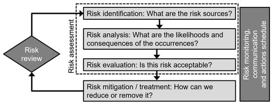
Figure 3.
Risk management process cycle, as understood in the context of this study.
A risk describes the magnitude of a hazard, and in its basic and prevailing mathematical definition it is formed from the product of the probability (p)—or the frequency (f)—of a damaging event E and the so-called average expectation of the consequences by the occurrence of the event E(D|E) [20]. An interdisciplinary view of the subject of matter to determine the possible sources of risk is essential in order to be able to complete the identification process comprehensively. It is important to mention that even with a thorough examination, not all risks can be determined in advance and they often only become apparent in the respective realization of the project. As suggested above, the most important factors of an identified risk are the probability of occurrence as well as the amount of damage when it occurs. The determination of the probability is therefore the entry point in the risk assessment. This can be achieved for example by inquiries or empirical values. In this way, a quantitative estimation regarding the probability of the occurrence of a certain risk is obtained. In addition to the probability of occurrence, the estimation or determination of the consequences upon occurrence, e.g., personal injury or damage to property, is established. The final assessment of a risk is based on the combination of probability and magnitude of the consequences. This results in a significant value for the determination of subsequent countermeasures. These measures can and should be considered, revised, and noted at every stage of the risk assessment. The value of the overall risk can be determined and visualized, for example, by a risk matrix. In addition, the introduction of a critical threshold into the risk matrix can serve to distinguish between negligible risks and critical risks that require unconditional implementation of reduction measures [21].
Risks can develop largely from human error as a primary factor (the error itself, may this be a workmanship defect or a miscalculation) or as a secondary factor (ignorance or negligence of threats). Residual risks are those parts of the risks that remain despite the execution of measures or are not recognized as a risk. Decisive for the residual risks is the correct consideration of the respective hazard recognition and the use of appropriate measures. For this reason, the following section focuses on the dangers arising from human error, as this is a fundamental source of error in the fastenings engineering industry.
Based on some studies [20,21,22], errors in the construction industry can have a multitude of causes. The study in [22] classifies the causes in personal, organisational, or project-specific, while they are also re-classified to lack of skills, lack of rules, or lack of ethics. Nevertheless, the probability of occurrence can be reduced by taking appropriate measures. Both technical and organizational measures can be applied. Above all, measures in the form of sufficient communications between the persons involved in the object as well as clear plans and work processes significantly reduce the error rate due to human error [20,23,24]. In addition, further training can increase the competence of those involved [22] and at least compensate to a certain extent for a lack of skills and knowledge.
Furthermore, in order to be able to amend the effects of possible errors that will occur despite appropriate measures, detection of the error is necessary. Therefore, a control by means of quality control and assurance is indispensable. An active communication makes it possible that errors can already be detected and corrected early by the subsequent participants. Part of this procedure is also a parallel independent supervision or inspection at all phases. Except for typical risk management practices, such measures are also proposed in Eurocode 0 Basis of design [25], which classifies, for example, three levels of design checking and three levels of inspection.
4. Expert Survey on Fastening Related Risks
4.1. Survey Methodology
The surveys were mainly conducted by means of interviews and served to identify possible sources of risk, their probability of occurrence and the extent of the consequences, as well as preventive measures and indications. Part of the data was collected by independently completing questionnaires. The criteria were based on the subjective assessments of the persons involved regarding the risks in fastening technology in the construction industry. These assessments depend on the experience as well as the field of activity of the respondents. The interviewed experts were chosen from different disciplines, including the manufacturing, construction, planning, and product certification fastening technology related sector. In total 16 experts were interviewed, of which 4 are affiliated to construction field work (25%), 7 are design and project management professionals (44%), 3 are involved with product testing and certification (19%), and 2 are at senior engineering positions in fastenings manufacturing (12%). The experts are based in the German-speaking, Central European region, but they have international professional activity. The average length of professional experience at the time of interview was 12.8 years, and they have all had project or area management roles.
The survey implemented structured interviews based on a pre-set questionnaire [26], however with the option for closed and open answers, so as to allow for opinions and explicit transfer of experiences [27]. The questionnaires were used as a basis for evaluation in the personal interviews and discourses with the respective persons regarding the possible risks in fastening technology with targeted questions. The questions addressed the description of the risk, the project’s stage when it may occur, likelihood, and impact of the risk. Open ended responses allowed also for consideration of countermeasures for the risks and assessments of further influences and dependencies, which are integrated in the recommendations section. Here it was possible to evaluate the probability of occurrence as well as the extent of the consequences of the occurrence of the respective risks by multiple choice. The main risk matrix has 3 ratings per probability and consequences, hence a three-grade system was provided in the questionnaire. In addition, the preventive measures and indications of the respective risks, which had been researched and elaborated in advance, were recorded in a table and presented to the interviewed professionals. The measures and information presented were evaluated in a discourse and subsequently statistically elaborated.
The contents of the questionnaire for the structured interview are presented below:
- 1.
- What is your name and affiliation (optional), your job title/subject area, and how long is your professional experience?
- 2.
- How high do you estimate the probability of the risks occurring in each of the given six categories in the draft register (see Table 1) and what do you estimate the consequences if they occur? Rating from 1 (low) to 3 (high)
 Table 1. Risk register for structural fastening risks based on the industry survey.
 - 3.
- Are you aware of other sources of risk and if so, which ones and how high do you estimate these (in terms of probability / consequences)?
- 4.
- Are the listed measures and instructions correct? Have you made any additions or remarks?
- 5.
- Do you have possible examples of the loss of load-bearing capacity of fasteners? And if so, how were these dealt with?
For the sake of clarity, an overall risk is indicated depending on the assessment of probability and consequences. The overall assessment of the risk is made up equally of probability and consequences. The respective values are multiplied as factors. A void/null response is not included in the assessment. The product thus results in the overall evaluation of the respective risk. In Figure 4, the implemented assessment basis is presented as a risk matrix. As with the probability and consequences, the rating is also graded as low, medium, and high with green, orange, and red markings, respectively. A low risk thus ranges between 1–2, a medium risk between 3–4, and a high risk between 6–9. The values are recorded with one decimal place and rounded accordingly for the indication of the mark. The results of the survey are presented in Table 1 below. The risk calculation averages the estimates of all respondents in the categories “Probability” (4th column) and “Consequence” (5th column) and then multiplies the averaged values to produce the anticipated risk (6th column).
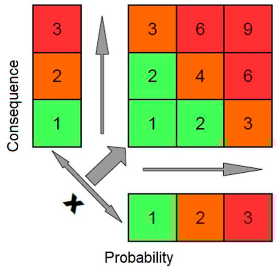
Figure 4.
Risk matrix.
4.2. Findings and Formation of Risk Register for Structural Fastening Risk
The data recorded in the risk register (Table 1) reflect the risk identification tendency in the fastening sector of the construction industry. The risk register is intended to reflect the findings of the survey and to provide planners with a clear and supportive aid for the implementation of fasteners in the construction industry. In addition, the list can help the people involved in the project to recall the possible sources of risks when employing fastening techniques.
A variety of critical aspects can be seen as regards the technical considerations addressed in Section 2. Regarding the load-transfer mechanism and hence type of the anchor (Section 2.1), there is little distinction to mechanical and bonded anchors and such product-specific risks. In general, risk No. 1.1 notes the risk of strength reduction due to loss of prestressing in expansion anchors, and reference to time-dependent material deterioration for mortars is mentioned as a load bearing deterioration agent in risk No. 3.1. Furthermore, no particular risks are mentioned in relation to cast-in place anchors, but hanger reinforcement (which is generally associated to cast-in systems) is recommended as a mitigation measure for a substrate that is expected to actually be of lower quality than planned. A distinction of product types can be seen at the installation-related risk group (risk Nos. 4.4–4.7), which address sub-standard structural performance due to sub-standard installation for bonded anchors.
Considerations of fastening types and assembly configurations (Section 2.2) are mostly represented in the risk group related to overall design (specifically risks Nos. 2.3–2.4).
Considerations of the substrate material (see Section 2.3) are also represented in the risk register. There is no specific distinction between concrete, masonry, or special types of substrates, such as lightweight concrete, but the observance of cracked concrete and the respective anchor specification and design is proposed as mitigation measure against failure due to poor substrate conditions.
The implementation of the appropriate product specifications that is discussed in Section 2.4 is noted as a possible risk (risk No. 2.1) with a relatively high ranking. Besides, it also is proposed as a mitigation measure in several occasions (e.g., risks related to corrosion, fatigue, fire performance), which highlights the importance of product selection considerations. An interesting finding is that risks related to product quality (risk group No. 5), which is inherent in the product technical specification, are results of quite low likelihood of occurrence. This is possibly interpreted as a trust of the interviewed population on the manufacturing sector.
Considerations on the correct use of structural design standards (Section 2.5) are not listed as a prevalent risk, but they are compliance to these standards is proposed as a mitigation measure for virtually all risks related in a way to the design calculations or planning phase. The standards proposed are, as expected, the newly introduced Eurocode 2—part 4, but also Eurocode 8 as regards seismic design.
As can be seen from the table, the most critical risks (with a rating rounding up to 6 or above) regardless of the underlying technical considerations are found to be related to borehole cleaning, load distribution on the anchors and the condition of the substrate. Special attention is paid to these critical risks and measures to minimize them should be included in the planning process.
For borehole cleaning, the evaluation was basically similar for all respondents. According to this, many had expressed a concern that the borehole cleaning during installation was inferior to what was prescribed or that it was not carried out by the correct work steps with suitable tools. Insufficient borehole cleaning sometimes leads to considerable reductions in resistance, especially in composite systems. The field study reported in [10] yielded comparably critical results with regard to the cleaning of boreholes in practice. In addition, the UK survey reported in [9] revealed that 21% of the planners have doubts about the correct installation of composite systems, while another 34% are only moderately confident. However, 84% of those surveyed consider borehole cleaning when using composite systems to be the most critical step in installation [9]. A critical analysis including possible actions to avoid sub-standard borehole preparation is therefore essential.
Ratings of significant emphasis were also given for the load distribution of groups of anchors in combination with an anchor plate. A correct assumption of the loads is crucial for proper design and load distribution. A sufficient stiffness of the anchor plate should always be aimed at for an even load distribution. In the case of transverse loads, the load transfer due to tolerances must be taken into account, and the annular gaps between the fixture holes and the anchorages can be filled in order to distribute the transverse loads evenly. In addition, elongated holes can be formed in the anchors near the edges in the direction of the transverse load in order to increase the resistance against edge breakouts of the concrete.
The condition of the substrate was also viewed as critical. The main concern was mostly related to the retrofitting or strengthening of existing structures and the related uncertainty of the materials, together with the position and density of the installed reinforcement. A preliminary examination of the substrate material and the performance of pull-out tests was to be considered in order to be able to achieve an efficient planning. In addition, tolerances in the placement of the reinforcement were considered of significant variation, even with sufficiently documented plans. Planning of increased expenditure due to probing and possible reinforcement encounters was considered an accountable effort.
Figure 5 exemplarily presents some materialised risks (i.e., actual defects and failures) corresponding to the risk register of Table 1.
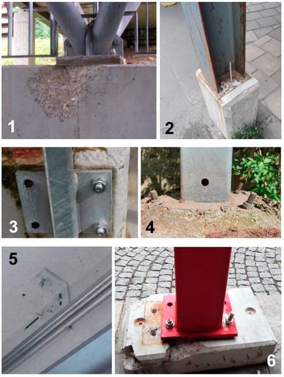
Figure 5.
Typical defects and failures associated to materialised risks listed in Table 1. 5-1: edge breakout due to small edge distances (risk No. 1.4); 5-2: inadequate embedment depth (risk No 4.3); 5-3: false configuration of the anchor plate (risk No. 2.3); 5-4: poor assessment of the anchorage base, negligence of non-structural layers and configuration according to standard (risk Nos. 2.5 and 4.8); 5-5: reinforcement strikes at drilling (risk No. 4.10); 5-6: inadequate assessment of the anchorage base and damage to building components (risk Nos. 2.5 and 4.11). All photos are taken by associates and students of the TU Dortmund—Chair of Fastenings Engineering; the fastening products shown are unknown and neither the authors nor their organisations are involved in these applications.
5. Discussion and Conclusions
Fastening technology provides an efficient solution to today’s rapid construction developments, automation, and fast evolving need for conversions and upgrades of objects in the construction industry. The technical communities’ interest to minimise the possibility of fastening failures is evident in the establishment of modern design standards, product standardisation and certification procedures, best practice guidance documents and special training events. However, as a result of the overall complexity of the fastenings sector in all project phases, a coherent risk management procedure against structural risks can prove vital for improved policy making and practices and advancement through research. This paper provides the fundamental concepts and methodology for the management of risks of fastening technology in construction. Furthermore, it provides a comprehensive and demonstrative accumulation of risks and mitigation measures based on an industry survey, with the aim to contribute to these directions.
The surveys and the evaluation of the data provide a tendency overview for the assessment of risks in fastening technology in the construction industry. It becomes clear in which areas improvements are possible and which areas should be given increased attention in order to ensure both safety and cost-effectiveness of fasteners in the construction industry. With regard to the possible risks, the engineers and planners focused their attention primarily on the area of installation. Often, increased safety factors or “Angsteisen” (additional precautionary anchors) were reckoned with for reasons of uncertainty regarding proper installation. Apart from the uneconomical planning, the lack of confidence in the trades involved in the execution of the work is to be viewed critically. Although the product evaluations refer to installation by appropriately trained personnel under the supervision of the site manager, the transparency in practice regarding proper installation by sufficiently trained personnel is questionable. In principle, the fastening technology is on the right track with training and certification of qualified personnel, but there is still a backlog demand, especially in the sensitization of contractors for safety-relevant fastenings and the corresponding installation. In principle, the installer trades in fastening technology but also the planning trades are recommended to take part in further training measures for their employees.
In the personal discourses with experts and practitioners during the surveys, opinions were often given regarding various other problems in fastening technology. The relatively complicated nature of both the design guidelines to be used and the selection of products was often mentioned. The main reasons for this can therefore be attributed to the low level of involvement with fastening technology in everyday professional life as well as the great variety of fastening systems in the market. The publication of the harmonized design guideline of Eurocode 2 Part 4 at least counteracted the wide range of prevailing design guidelines. This provided planners with a uniform and at the same time clearer design basis. Furthermore, many of the planning engineers expressed the wish that a more transparent overview of the basic application areas of the individual fastening systems would be useful. This is where manufacturers in the field of fastening technology see potential for facilitating the selection of a sensible and appropriate fastening system for engineers and planners outside of the typical product ranges and making their products more accessible to these disciplines.
Based on the survey presented herein, the following takeaways can be summarised, which can be of use and interest for all disciplines involved with fastening in research, design, project management, and construction:
- Risk management of fastenings can be largely assisted by use of a risk register. The study herein proves that listing and categorising risks, rating them, and linking those to risk mitigation measures is feasible. Moreover, this process can in this form facilitate an overview, monitoring and communication of relevant engineering risks.
- A risk register for fastenings, is made available herein for the first time in international literature, and it can be used as guidance or as a model for risk registers of projects involving fastenings.
- Questionnaires for semi-structured expert interviews are developed specifically for this study, with the option to be improved as the interviews progress. This also guarantees that the proposed risk register indicates actual risks and the outcome is strongly related to practice.
- The highest-ranking risks are found to be related to borehole cleaning, load distribution on the anchors and the condition of the substrate. While practicing engineers must devote particular attention to these risks, future research, standardisation, and technological innovation should also address the causes and consequences of these risks in order to possibly further reduce them.
- The lowest ranking risks (i.e., with a rating below 3), appear to be related on the one hand with the last steps of fastening installations (i.e., torqueing of anchors and adjusting the fixture to its final position), and on the other hand with the anticipated product quality.
It should be highlighted that the presented study may be disclosing useful information as noted above but it relies on relatively limited number of questionnaires, moreover from a certain geographic region (Central Europe). Some types of fastening systems (e.g., cast-in systems), or substrate types (e.g., various masonry types) may be underrepresented, since they are hardly addressed in the risk identification or mitigation records. Maintaining the survey process developed herein, and relying on the experience and findings gained by the present survey, a further study may be able to provide a model risk register with wider risk considerations and area of applicability.
Author Contributions
Conceptualization, P.S.; methodology, P.S.; formal analysis, R.K. (Rene Kudszus) and P.S.; investigation, R.K. (Rene Kudszus); resources, R.K. (Robert Klemencic) and P.S.; data curation, R.K. (Rene Kudszus); writing—original draft preparation, R.K. (Rene Kudszus) and P.S.; writing—review and editing, R.K. (Robert Klemencic) and P.S.; visualization, R.K. (Rene Kudszus) and P.S.; supervision, R.K. (Robert Klemencic) and P.S.; project administration, R.K. (Robert Klemencic) and R.K. (Rene Kudszus). All authors have read and agreed to the published version of the manuscript.
Funding
This research received no external funding.
Acknowledgments
The authors extend their appreciation for the input by several industry practitioners and experts contributing their knowledge and opinions, and to students of the TU Dortmund for photos used in Figure 5.
Conflicts of Interest
The authors declare no conflict of interest.
References
- NTSB (National Transportation Safety Board). Ceiling Collapse in the Interstate 90 Connector Tunnel, Boston, Massachusetts, July 10, 2006; Highway Accident Report NTSB/HAR-07/02; NTSB: Washington, DC, USA, 2006. [Google Scholar]
- NASA (National Aeronautics and Space Administration). Tunnel of Terror. Available online: https://sma.nasa.gov/docs/default-source/safety-messages/safetymessage-2008-06-01-thebigdigceilingtilecollapse.pdf?sfvrsn=e3a91ef8_4 (accessed on 17 September 2020).
- Kawahara, S.; Doi, H.; Shirato, M.; Kajifusa, N.; Kutsukake, T. Investigation of the tunnel ceiling collapse in the Central Expressway in Japan. In Proceedings of the Trans-Portation Research Board 93rd Annual Meeting, Washington, DC, USA, 12–16 January 2014. [Google Scholar]
- Peyer, B. Untersuchungsergebnisse zum Unglück im Hallenbad Uster (Investigation results of the accident in the indoor swimming pool Uster—In German). Schweiz. Bauztg. 1987, 105, 184–185. [Google Scholar]
- Faller, M.; Richner, P. Sicherheitsrelevante Bauteile in Hallenbädern. Werkstoffwahl und Kontrollierbarkeit. Schweiz. Ing. Archit. 2000, 118, 364–370. [Google Scholar]
- Stacy, M.; Denton, S.; Pottle, S. Management of safety-critical fixings. In Guidance for the Management and Design of Safety-Critical Fixings (C778); CIRIA—Construction Industry Research and Information Association: London, UK, 2019. [Google Scholar]
- Soane, A. Temporary Works Toolkit.: Part 5: Temporary works failures—What are the common causes? Struct. Eng. J. Inst. Struct. Eng. 2017, 95, 24–26. [Google Scholar]
- Andresen, J. Investigation of a collapsed scaffold structure. Proc. Inst. Civ. Eng. Forensic Eng. 2012, 165, 95–104. [Google Scholar] [CrossRef]
- Cronyn, B. New Civil Engineer. Available online: https://www.newcivilengineer.com/latest/industry-fears-over-fixings-10-09-2015/ (accessed on 17 September 2020).
- Grosser, P.; Fuchs, W.; Eligehausen, R. A field study of adhesive anchor installations. Concr. Int. 2011, 33, 57–63. [Google Scholar]
- CEN—European Committee for Standardization. EN 1992-4:2018 Design of Concrete Structures; Design of Fastenings for Use in Concrete (Eurocode 2—Part 4); CEN: Brussels, Belgium, 2018. [Google Scholar]
- DIBt—Deutsches Institut für Bautechnik [German Institute for Construction Engineering]. Hinweise für die Montage von Dübelverankerungen [Instructions for the Installation of Dowel Anchors]; DIBt: Berlin, Germany, 2010. [Google Scholar]
- BSI—British Standards Institute. BS 8539:2012—Code of Practice for the Selection and Installation of Post-Installed Anchors in Concrete and Masonry; BSI: London, UK, 2012. [Google Scholar]
- American Concrete Institute. Building Code Requirements for Structural Concrete (ACI 318-14): Commentary on Building Code Requirements for Structural Concrete (ACI 318R-14): An ACI Report; American Concrete Institute: Farmington Hills, MI, USA, 2014. [Google Scholar]
- Cook, R.A. Behavior of chemically bonded anchors. J. Struct. Eng. 1993, 119, 2744–2762. [Google Scholar] [CrossRef]
- Eligehausen, R.; Mallée, R.; Silva, J.F. Anchorage in Concrete Construction; John Wiley & Sons: Hoboken, NJ, USA, 2006. [Google Scholar]
- EOTA—European Organization for Technical Approvals. ETAG 001: Guideline for European Technical Approval of Metal Anchors for Use in Concrete, Annex C: Design Methods for Anchorages, 3rd Amendment; EOTA: Brussels, Belgium, 2010. [Google Scholar]
- European Parliament and Council. EU Regulation No. 305/2011 Construction Products Regulation (CPR); European Parliament and Council: Brussels, Belgium, 2011. [Google Scholar]
- ISO—International Standards Organisation. ISO 31000:2018 Risk Management—Principles and Guidelines; ISO: Geneva, Switzerland, 2018. [Google Scholar]
- Schneider, J.; Vrouwenvelder, T. Introduction to Safety and Reliability of Structures; IABSE: Zurich, Switzerland, 2017; Volume 5. [Google Scholar]
- Smith, N.J.; Merna, T.; Jobling, P. Managing Risk in Construction Projects; John Wiley & Sons: Hoboken, NJ, USA, 2014. [Google Scholar]
- Lopez, R.; Love, P.E.; Edwards, D.J.; Davis, P.R. Design error classification, causation, and prevention in construction engineering. J. Perform. Constr. Facil. 2010, 24, 399–408. [Google Scholar] [CrossRef]
- Ellingwood, B. Design and construction error effects on structural reliability. J. Struct. Eng. 1987, 113, 409–422. [Google Scholar] [CrossRef]
- Garrett, J.W.; Teizer, J. Human factors analysis classification system relating to human error awareness taxonomy in construction safety. J. Constr. Eng. Manag. 2009, 135, 754–763. [Google Scholar] [CrossRef]
- CEN—European Committee for Standardization. EN 1990: 2002—Basis of Structural Design (Eurocode 0); CEN: Brussels, Belgium, 2002. [Google Scholar]
- Wood, L.E.; Ford, J.M. Structuring interviews with experts during knowledge elicitation. Int. J. Intell. Syst. 1993, 8, 71–90. [Google Scholar] [CrossRef]
- Booker, J.M.; McNamara, L.A. Expert knowledge in reliability characterization: A rigorous approach to eliciting, documenting, and analyzing expert knowledge. In Engineering Design Reliability Handbook; CRC Press: Boca Raton, FL, USA, 2005; Chapter 13. [Google Scholar]
Publisher’s Note: MDPI stays neutral with regard to jurisdictional claims in published maps and institutional affiliations. |
© 2020 by the authors. Licensee MDPI, Basel, Switzerland. This article is an open access article distributed under the terms and conditions of the Creative Commons Attribution (CC BY) license (http://creativecommons.org/licenses/by/4.0/).