
Software Architecture Modeling of AUTOSAR-Based Multi-Core Mixed-Critical Electric Powertrain Controller


Abstract
:1. Introduction
1.1. State-of-the-Practice in Automotive Organizations
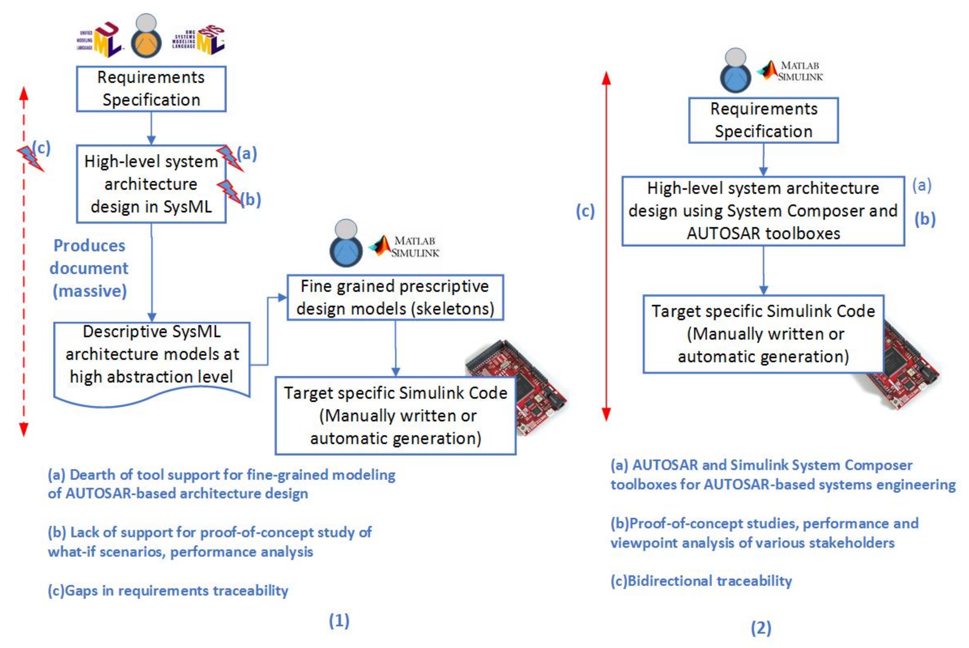
Main Pitfalls in State-of-the-Art Practice
- Dearth of feature rich tool support for detailed modeling and software architecture design of AUTOSAR-based systems (e.g., no detailed data dictionary);
- Lack of support (e.g., simulations) for proof-of-concept study of what-if scenarios and trade-off analysis of performance requirements (e.g., timing, memory, energy, and safety) during early architectural design;
- Lack of bidirectional requirements traceability and a comprehensive authoring process.
1.2. Proposed Approach
- Employing AUTOSAR specific block set in the latest releases of M/S, we were able to implement a detailed model-based software architecture design of AUTOSAR system including a detailed data dictionary;
- Making use of the Simulink System Composer toolbox in the recent releases of M/S, we have created custom-defined profiles to support trade-off analysis of safety software (e.g., safety vs. timing);
- Using powerful simulations supported by M/S toolboxes, we were also able to carry out umpteen proof-of-concept studies and what-if scenario simulations;
- With the help of a state-of-the-art requirements management tool plugin (Polarion for Simulink [9]) and custom-defined scripts, we achieved seamless bidirectional traceability between requirements and architecture design. This is also supported by a comprehensive authoring process.
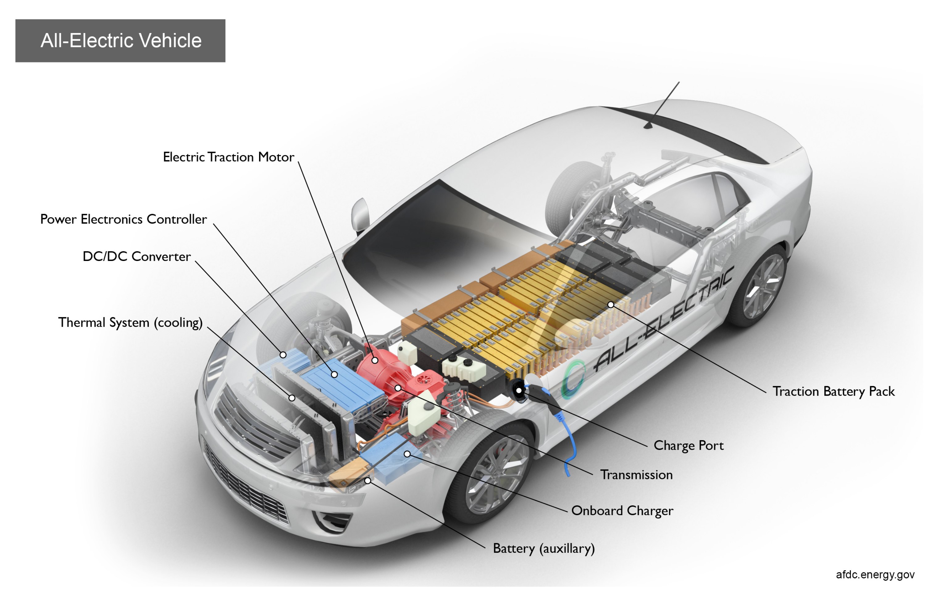
1.3. Electric Powertrain Example
2. Background and Related Work
2.1. Modeling Automotive Embedded Software Systems
2.2. Modeling and Simulation-Based Techniques Using UML and SysML
2.2.1. UML/SysML Tools for AUTOSAR-Based Architecture Modeling
2.2.2. Matlab/Simulink (M/S) Tool for AUTOSAR-Based Architecture Modeling
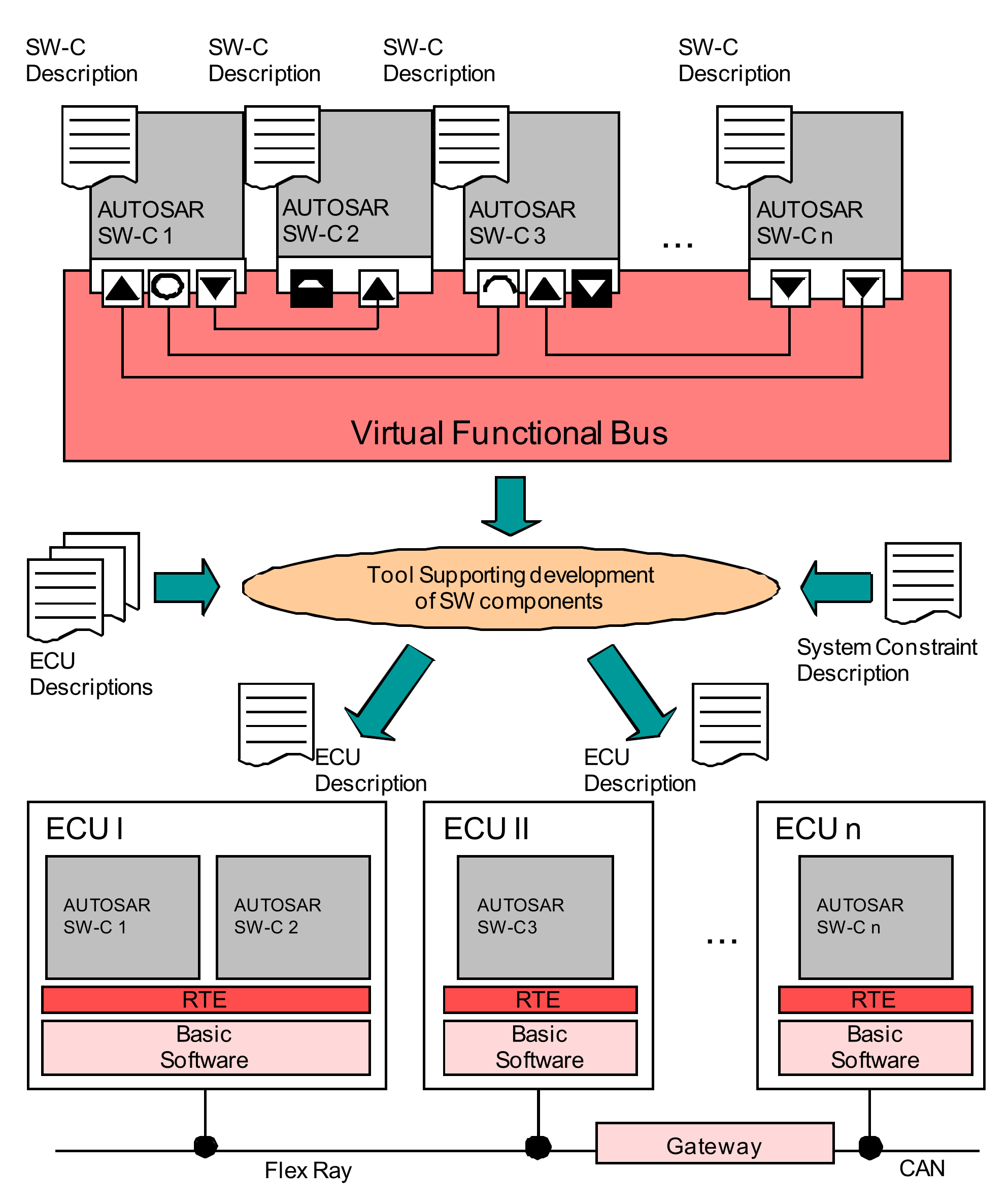
2.2.3. AUTOSAR Framework
2.3. Requirements Management (RM) Tools
3. Pitfalls in Legacy Approach and Best Practices in New Approach
3.1. Modeling AUTOSAR-Based Software Architecture
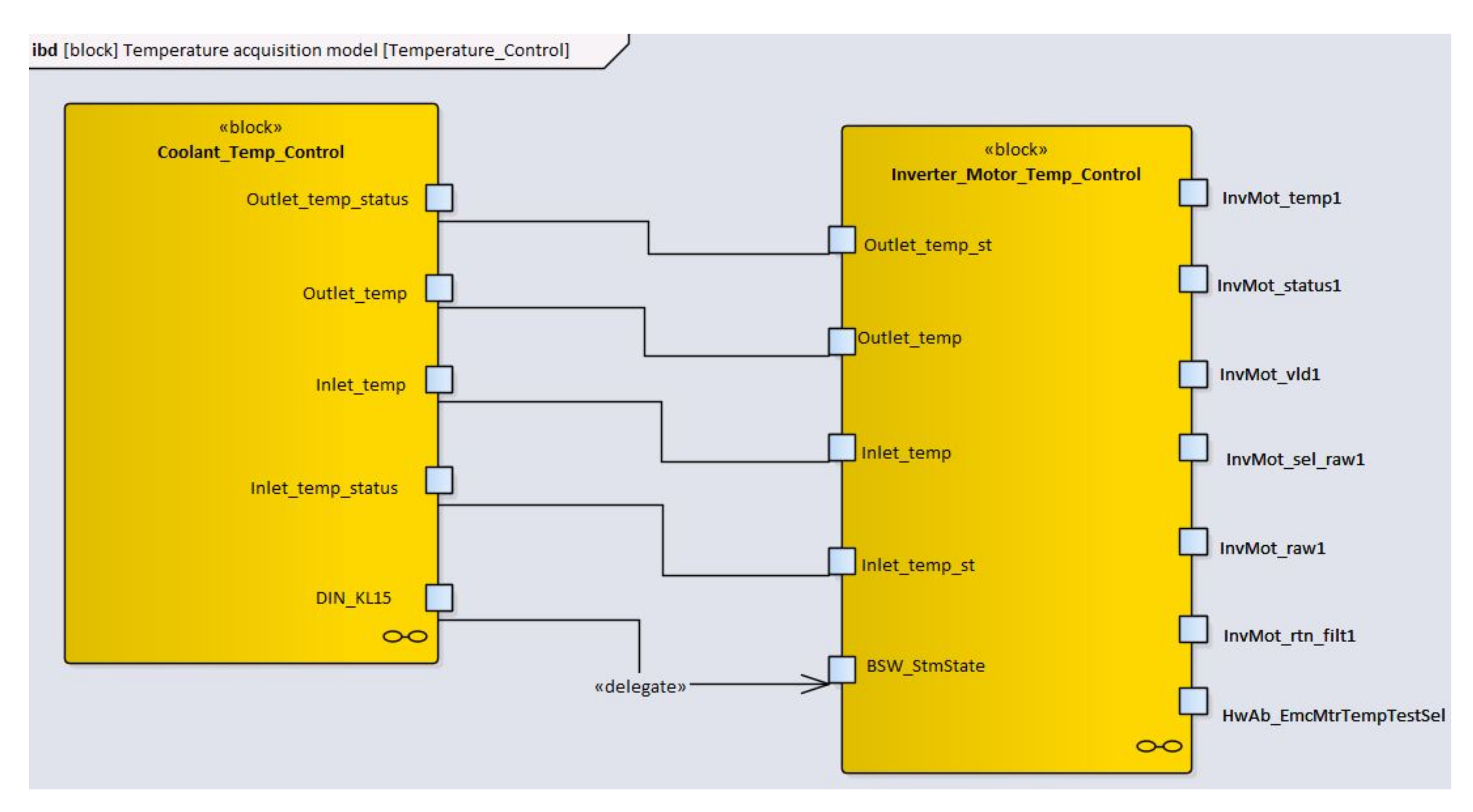
3.1.1. Using SysML/EA
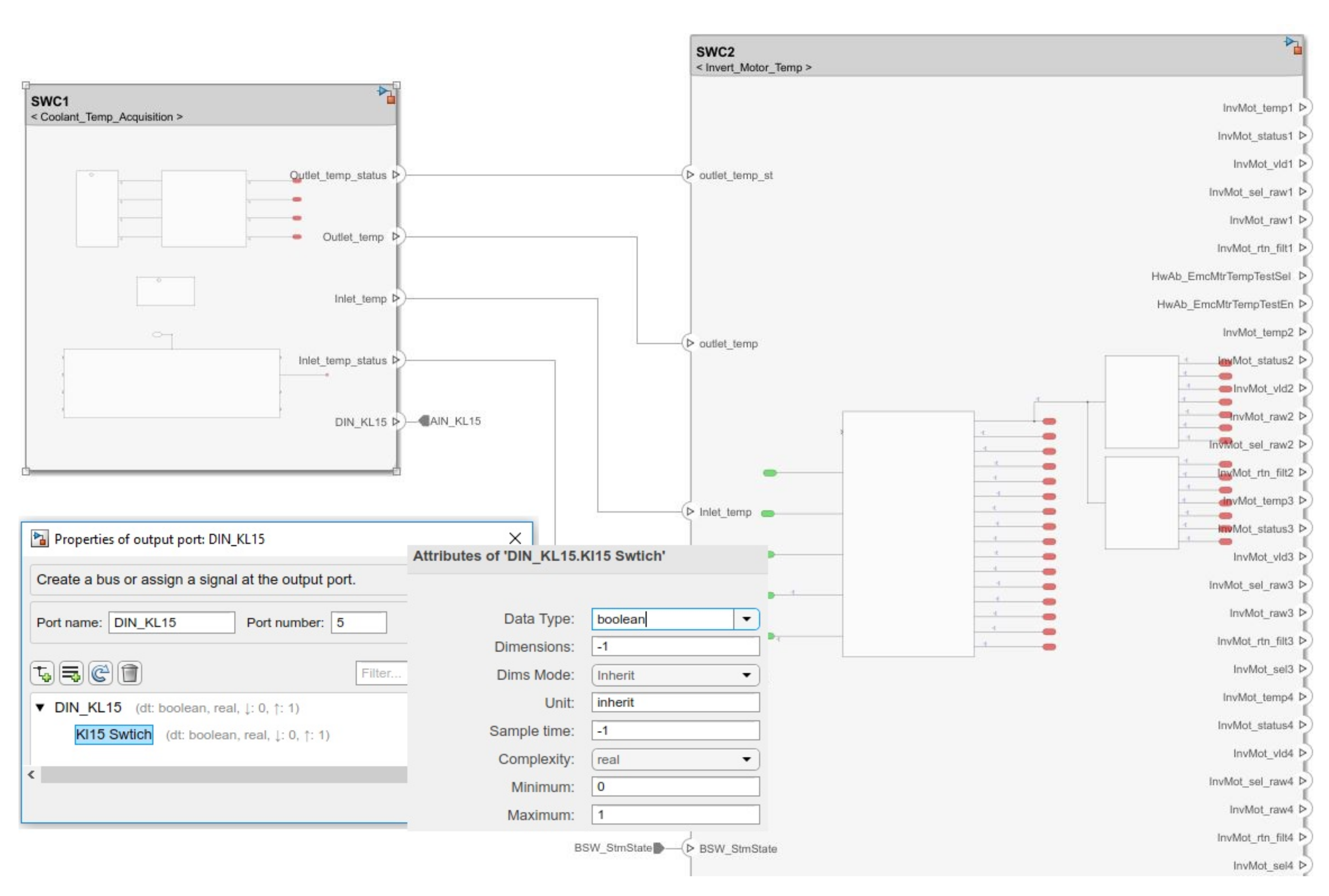
3.1.2. Using System Composer and AUTOSAR Blockset in M/S
- Best Practice-1 (BP-1): Modeling of AUTOSAR-based system architecture using AUTOSAR blockset together with System composer toolbox in recent releases of M/S;
- BP-2: Creating fine-grained AUTOSAR architecture models using Simulink System Composer data dictionary support.
3.2. Early Model-Based Performance Analysis
3.2.1. AUTOSAR Watchdog Manager (WdgM)
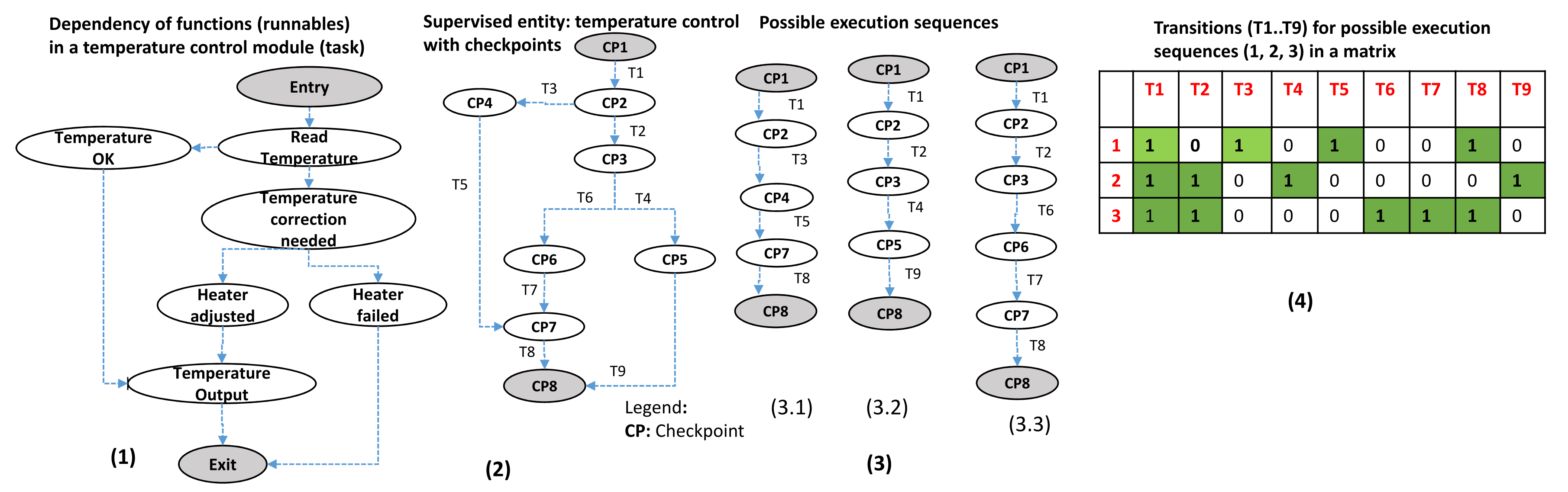
3.2.2. Supervised Entities, Checkpoints and Program Flow Graph
3.2.3. Granularity of Checkpoints
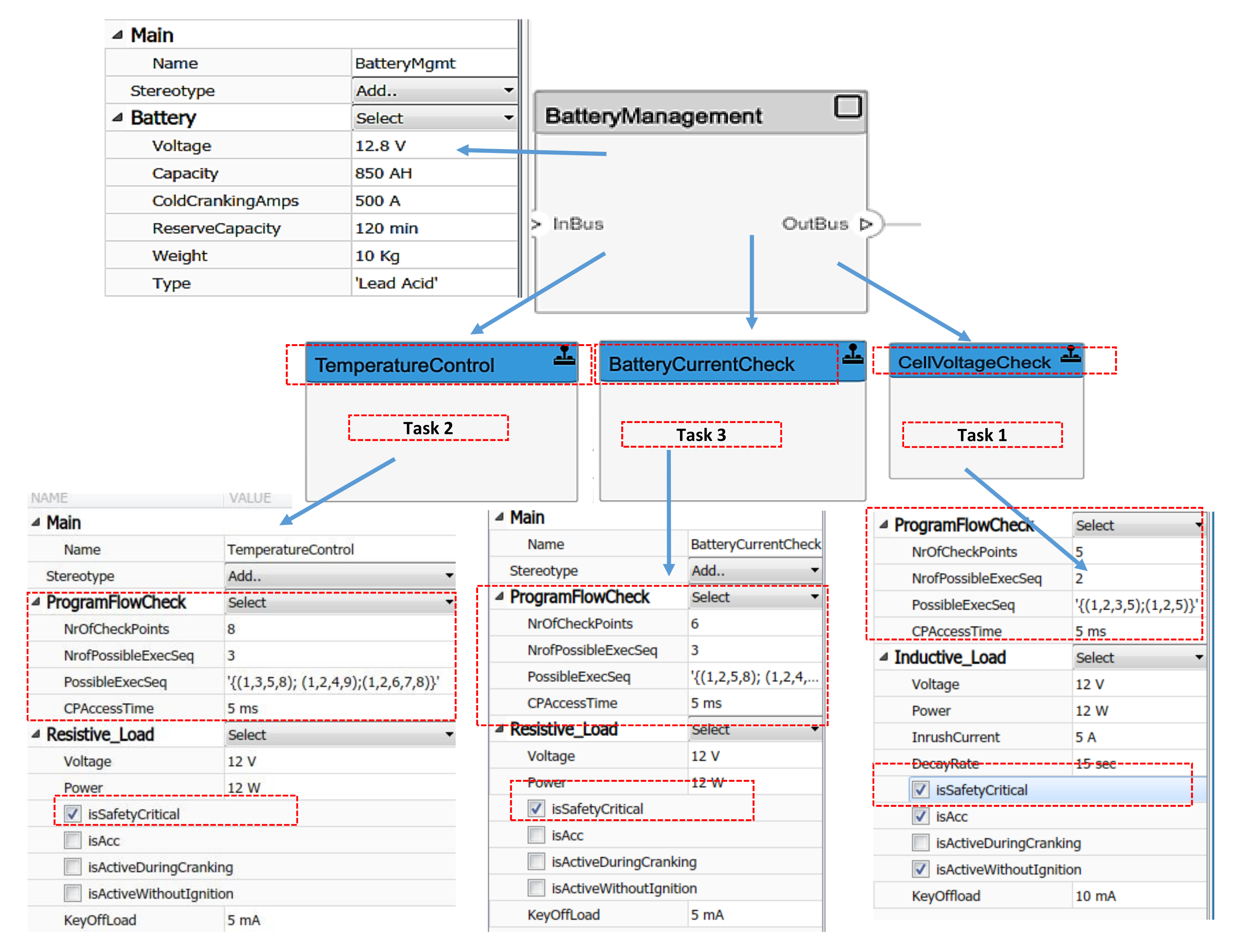
3.2.4. Battery Management System Example
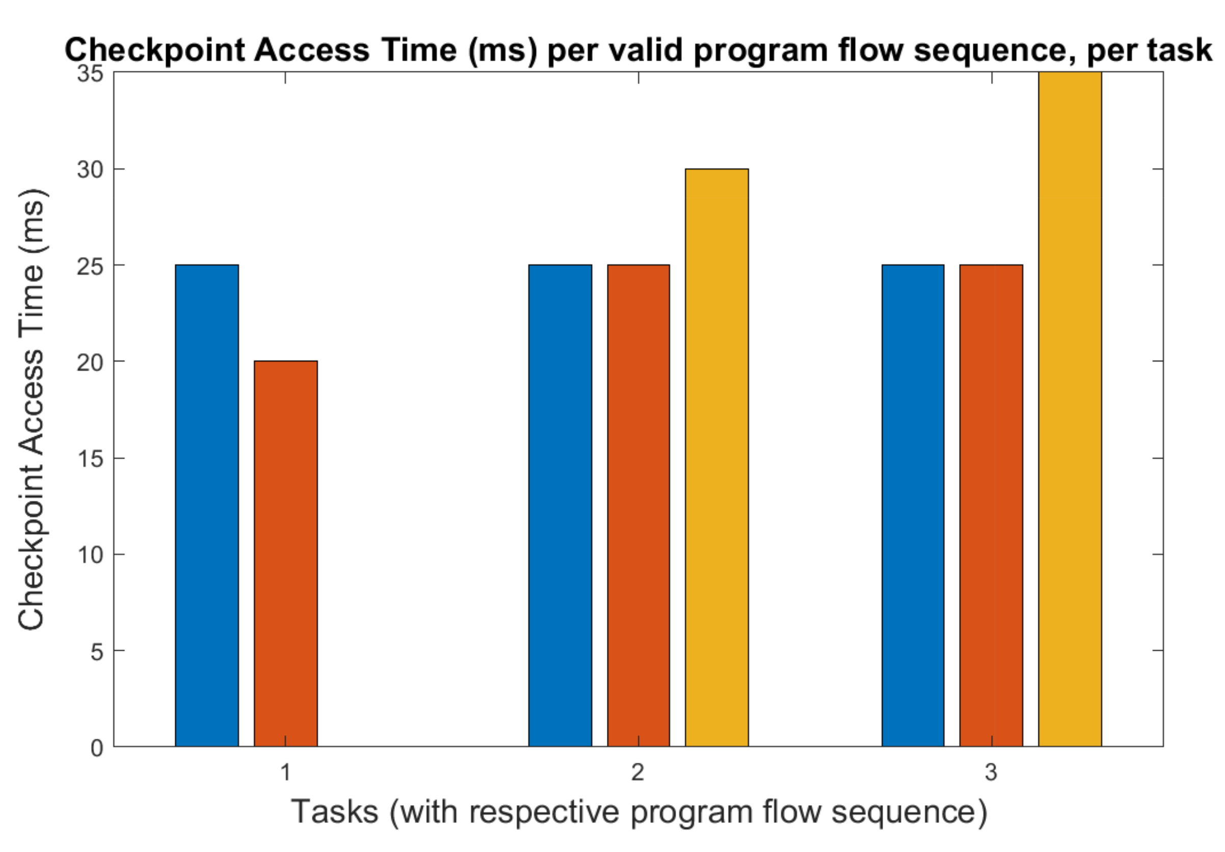
3.2.5. Estimation Using Matlab Script
3.2.6. Model-Based Estimation
3.2.7. Concept Phase of the Project—An Example
- BP-3: Early model-based performance and trade-off analysis of non-functional requirements using custom-defined profiles (e.g., employing M/S-SC toolbox [32]).
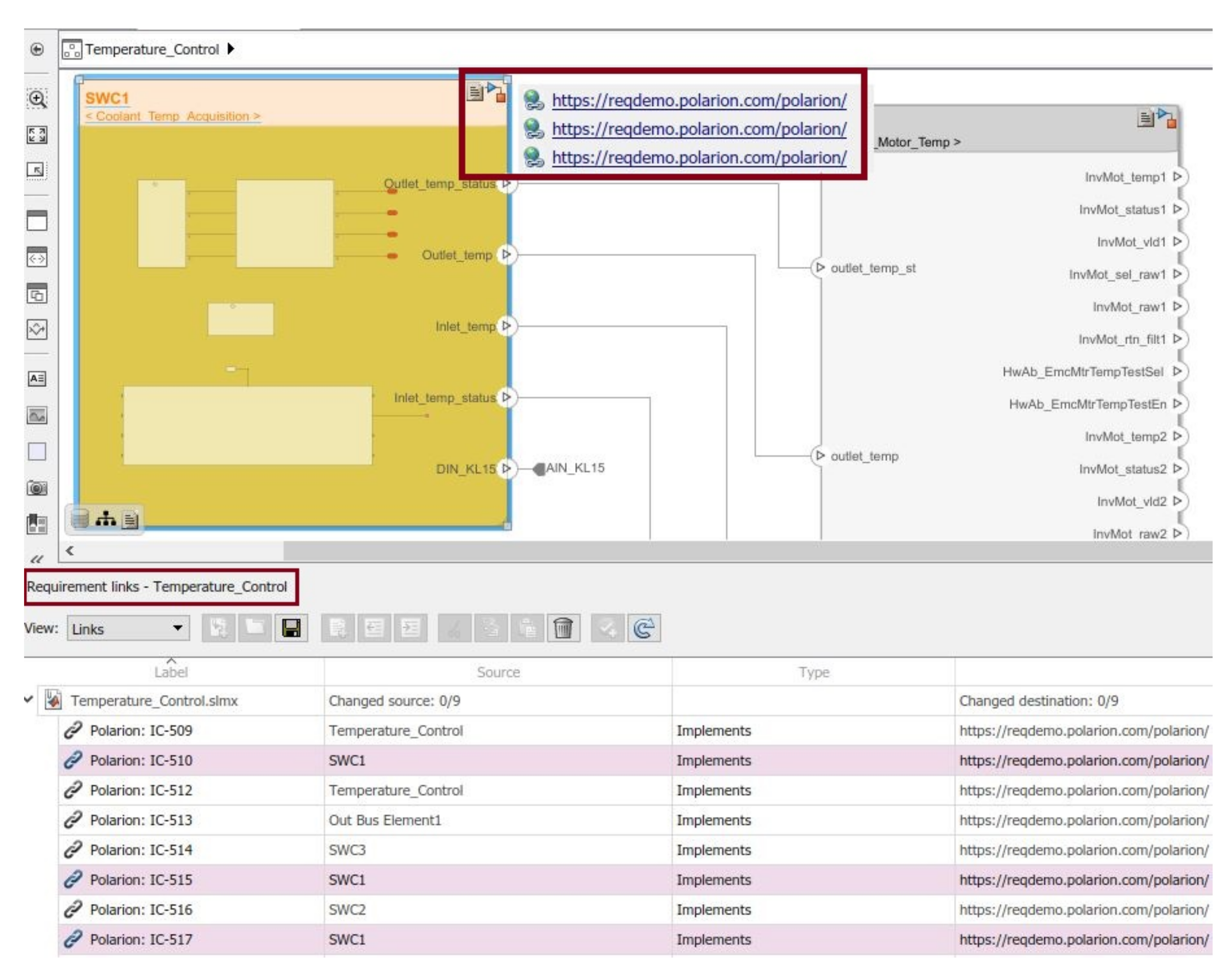
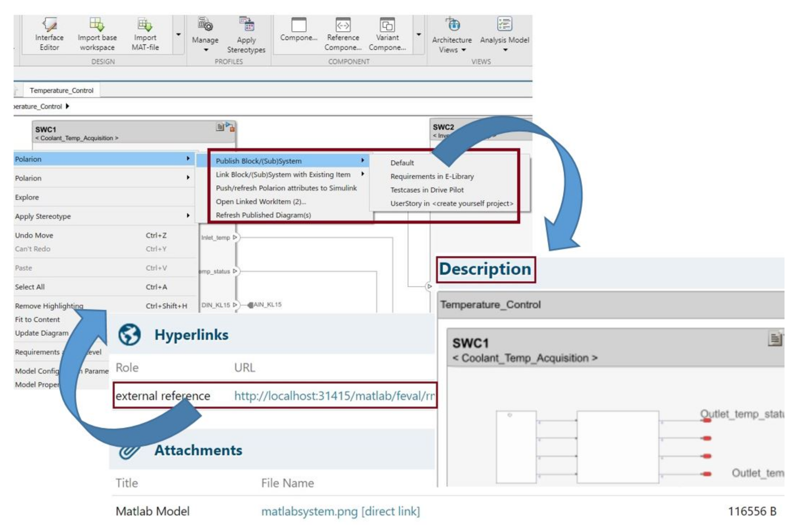
3.3. Bidirectional Traceability
3.3.1. Publishing and Authoring
3.3.2. Basic Software Configuration Using ARXML Schema
- BP-4: Employing seamless approach for high-level system and software architectural design with data dictionary support, helps to establish bidirectional traceability between modeling environment and the requirements database. Tracking of requirements back and forth between both the environments to verify fulfillment of requirements;
- BP-5: Use of a state-of-the-art plug-in between requirements management tool (Polarion) and System architecture design tool (M/S-SC) to publish requirements and design on to requirements database. Additionally, the approach updates both requirements and design whenever adapted for changes due to technical analysis and discussions in a more efficient way;
- BP-6: Import and export of ARXMLs between architectural modeling environment to Basic software (BSW) configuration and development tool-chain to reduce ambiguity on architectural considerations and development time.
4. Lessons Learned
5. Summary and Conclusions
Author Contributions
Funding
Conflicts of Interest
References
- van der Sanden, B.; Li, Y.; van den Aker, J.; Akesson, B.; Bijlsma, T.; Hendriks, M.; Triantafyllidis, K.; Verriet, J.; Voeten, J.; Basten, T. Model-Driven System-Performance Engineering for Cyber-Physical Systems: Industry Session Paper. In Proceedings of the 2021 International Conference on Embedded Software (EMSOFT), Austin, TX, USA, 10–15 October 2021; pp. 11–22. [Google Scholar]
- Sangiovanni-Vincentelli, A.; Natale, M.D. Embedded System Design for Automotive Applications. Computer 2007, 40, 42–51. [Google Scholar] [CrossRef]
- AUTomotive Open System ARchitecture (AUTOSAR). Available online: https://www.autosar.org/ (accessed on 21 September 2021).
- UML Specification. Available online: https://www.omg.org/spec/UML/About-UML/ (accessed on 21 September 2021).
- SysML Specification. Available online: http://www.omgsysml.org/ (accessed on 21 September 2021).
- Mathworks Products. Available online: https://www.mathworks.com/ (accessed on 21 September 2021).
- Enterprise Architect Tool. Available online: https://www.sparxsystems.com.au/products/ea/index.html (accessed on 21 September 2021).
- IBM Software. IBM Rational Rhapsody Developer. Available online: https://www.ibm.com/products/systems-design-rhapsody (accessed on 21 September 2021).
- Polarion ALM Connector for Simulink. Available online: https://extensions.polarion.com/extensions/173-polarion-connector-for-simulink (accessed on 21 September 2021).
- Martinez, L.R.; Prieto, M.D. New Trends in Electrical Vehicle Powertrains, 1st ed.; Intech Open: London, UK, 2019. [Google Scholar]
- ISO26262-Road Vehicles Functional Safety Standard. Available online: https://www.iso.org/standard/68383.html (accessed on 21 September 2021).
- OMG. Object Management Group. Available online: https://www.omg.org/ (accessed on 21 September 2021).
- Bucaioni, A.; Cicchetti, A.; Ciccozzi, F.; Mubeen, S.; Sjödin, M. A Metamodel for the Rubus Component Model: Extensions for Timing and Model Transformation From EAST-ADL. IEEE Access 2017, 5, 9005–9020. [Google Scholar] [CrossRef]
- Mubeen, S.; Nolte, T.; Sjödin, M.; Lundbäck, J.; Lundbäck, K.L. Supporting timing analysis of vehicular embedded systems through the refinement of timing constraints. J. Softw. Syst. Model. 2019, 18, 36–69. [Google Scholar] [CrossRef] [Green Version]
- Bocciarelli, P.; D’Ambrogio, A.; Giglio, A.; Gianni, D. A SaaS-based automated framework to build and execute distributed simulations from SysML models. In Proceedings of the Winter Simulations Conference (WSC), Washington, DC, USA, 8–11 December 2013; pp. 1371–1382. [Google Scholar]
- Bocciarelli, P.; D’Ambrogio, A.; Giglio, A.; Paglia, E. Model-Driven Distributed Simulation Engineering. In Proceedings of the Winter Simulation Conference (WSC ’19), National Harbor, MD, USA, 8–11 December 2019; IEEE Press: Piscataway, NJ, USA, 2019; pp. 75–89. [Google Scholar]
- Sporer, H. A Model-Based Domain-Specific Language Approach for the Automotive E/E-System Design; Association for Computing Machinery: New York, NY, USA, 2015; pp. 357–362. [Google Scholar]
- Mhenni, F.; Nguyen, N.; Choley, J.Y. SafeSysE: A Safety Analysis Integration in Systems Engineering Approach. IEEE Syst. J. 2018, 12, 161–172. [Google Scholar] [CrossRef]
- Mhenni, F.; Choley, J.Y.; Penas, O.; Plateaux, R.; Hammadi, M. A SysML-based methodology for mechatronic systems architectural design. Adv. Eng. Inform. 2014, 28, 218–231. [Google Scholar] [CrossRef]
- Andrianarison, E.; Piques, J.D. SysML for embedded automotive Systems: A practical approach. In Proceedings of the ERTS2 2010, Embedded Real Time Software & Systems, Toulouse, France, 19–21 May 2010. [Google Scholar]
- Daniele, G.; Andrea, D.; Andrea, S.T. Modeling and Simulation-Based Systems Engineering Handbook; CRC Press: Boca Raton, FL, USA, 2015. [Google Scholar]
- Zacharewicz, G.; Daclin, N.; Doumeingts, G.; Haidar, H. Model Driven Interoperability for System Engineering. Modelling 2020, 1, 94–121. [Google Scholar] [CrossRef]
- Ducq, Y.; Chen, D.; Alix, T. Principles of Servitization and Definition of an Architecture for Model Driven Service System Engineering. In Enterprise Interoperability; van Sinderen, M., Johnson, P., Xu, X., Doumeingts, G., Eds.; Springer: Berlin/Heidelberg, Germany, 2012; pp. 117–128. [Google Scholar]
- Sundharam, S.M.; Havet, L.; Altmeyer, S.; Navet, N. A model-based development environment for rapid-prototyping of latency-sensitive automotive control software. In Proceedings of the Sixth International Symposium on Embedded Computing and System Design (ISED), Patna, India, 15–17 December 2016; IEEE: Piscataway, NJ, USA, 2016; pp. 228–233. [Google Scholar]
- Sundharam, S.M.; Navet, N.; Altmeyer, S.; Havet, L. A Model-Driven Co-Design Framework for Fusing Control and Scheduling Viewpoints. Sensors 2018, 18, 628. [Google Scholar] [CrossRef] [PubMed] [Green Version]
- Petriu, D.C. Software Model-based Performance Analysis. In Model-Driven Engineering for Distributed Real-Time Systems; John Wiley & Sons, Inc.: Hoboken, NJ, USA, 2013; pp. 139–166. [Google Scholar]
- Iyenghar, P.; Huning, L.; Pulvermüller, E. Early Synthesis of Timing Models in AUTOSAR-based Automotive Embedded Software Systems. In Proceedings of the 8th International Conference on Model-Driven Engineering and Software Development, Valletta, Malta, 25–27 February 2020; pp. 26–38. [Google Scholar]
- Jianqiang, W.; Shengbo, L.; Xiaoyu, H.; Keqiang, L. Driving simulation platform applied to develop driving assistance systems. IET Intell. Transp. Syst. 2010, 4, 121–127. [Google Scholar] [CrossRef] [Green Version]
- Franco, F.R.; Neme, J.H.; Santos, M.M.; da Rosa, J.N.; Dal Fabbro, I.M. Workflow and toolchain for developing the automotive software according AUTOSAR standard at a Virtual-ECU. In Proceedings of the IEEE 25th International Symposium on Industrial Electronics (ISIE), Santa Clara, CA, USA, 8–10 June 2016; pp. 869–875. [Google Scholar]
- Vatanparvar, K.; Faruque, M.A.A. Design and Analysis of Battery-Aware Automotive Climate Control for Electric Vehicles. ACM Trans. Embed. Comput. Syst. 2018, 17, 1–22. [Google Scholar] [CrossRef]
- Mathworks AUTOSAR Blockset. Available online: https://www.mathworks.com/products/autosar.html (accessed on 21 September 2021).
- System Composer Toolbox. Available online: https://www.mathworks.com/products/system-composer.html (accessed on 21 September 2021).
- Navet, N.; Simonot-Lion, F. (Eds.) Automotive Embedded Systems Handbook; CRC Press: Boca Raton, FL, USA, 2009. [Google Scholar]
- AUTOSAR Release 4.4.0: Methodology and Templates. Available online: https://www.autosar.org/standards/classic-platform/classic-platform-440/ (accessed on 21 September 2021).
- DOORS Requirements Management Tool. Available online: https://www.ibm.com/products/requirements-management (accessed on 21 September 2021).
- Requirements Management for Eclipse. Available online: https://www.eclipse.org/rmf/ (accessed on 21 September 2021).
- ReqIF. Requirements Interchange Format. Available online: https://www.omg.org/spec/ReqIF/About-ReqIF/ (accessed on 21 September 2021).
- Best Practices for Traceability of Functional Safety Requirements in Automotive. Available online: https://hosteddocs.emediausa.com/synopsys-asset-2-aug-2019.pdf (accessed on 21 September 2021).
- Polarion Extension for Enterprise Architect. Available online: https://extensions.polarion.com/extensions/167-polarion-connector-for-enterprise-architect (accessed on 21 September 2021).
- Vitkin, L.; Fallahi, A. The Role of the Data Dictionary in the Model-Based Development Process; SAE Technical Paper; SAE International: Warrendale, PA, USA, 2009. [Google Scholar]
- Modeling Guidelines of Basic Software Enterprise Architect UML Models, AUTOSAR CP Release 4.3.0. Available online: https://www.autosar.org/fileadmin/user_upload/standards/classic/4-3/AUTOSAR_TR_BSWUMLModelModelingGuide.pdf (accessed on 21 September 2021).
- Specification of Watchdog Manager-AUTOSAR CP Release 4.3.1. Available online: https://www.autosar.org/fileadmin/user_upload/standards/classic/4-3/AUTOSAR_SWS_WatchdogManager.pdf (accessed on 21 September 2021).
- DaVinci Configurator. Available online: https://www.vector.com/de/en/products/products-a-z/software/davinci-configurator-pro/ (accessed on 21 September 2021).
- Iyenghar, P.; Huning, L.; Pulvermüller, E. Model-Based Timing Analysis of Automotive Use Case Developed in UML. In Proceedings of the Evaluation of Novel Approaches to Software Engineering-15th International Conference, ENASE 2020, Prague, Czech Republic, 5–6 May 2020; Ali, R., Kaindl, H., Maciaszek, L.A., Eds.; Revised Selected Papers; Springer: Berlin/Heidelberg, Germany, 2020; Volume 1375, pp. 360–385. [Google Scholar]
- Iyenghar, P.; Pulvermueller, E. A Model-Driven Workflow for Energy-Aware Scheduling Analysis of IoT-Enabled Use Cases. IEEE Internet Things J. 2018, 5, 4914–4925. [Google Scholar] [CrossRef]
- Automotive Software Performance Improvement and Capability Determinitation (ASPICE). Available online: http://www.automotivespice.com/ (accessed on 21 September 2021).
- GLIWA Embedded Systems, Timing Suite T1. Available online: https://www.gliwa.com/index.php?page=products_T1&lang=eng (accessed on 21 September 2021).


Publisher’s Note: MDPI stays neutral with regard to jurisdictional claims in published maps and institutional affiliations. |
© 2021 by the authors. Licensee MDPI, Basel, Switzerland. This article is an open access article distributed under the terms and conditions of the Creative Commons Attribution (CC BY) license (https://creativecommons.org/licenses/by/4.0/).
Share and Cite
Sundharam, S.M.; Iyenghar, P.; Pulvermueller, E. Software Architecture Modeling of AUTOSAR-Based Multi-Core Mixed-Critical Electric Powertrain Controller. Modelling 2021, 2, 706-727. https://doi.org/10.3390/modelling2040038
Sundharam SM, Iyenghar P, Pulvermueller E. Software Architecture Modeling of AUTOSAR-Based Multi-Core Mixed-Critical Electric Powertrain Controller. Modelling. 2021; 2(4):706-727. https://doi.org/10.3390/modelling2040038
Chicago/Turabian StyleSundharam, Sakthivel Manikandan, Padma Iyenghar, and Elke Pulvermueller. 2021. "Software Architecture Modeling of AUTOSAR-Based Multi-Core Mixed-Critical Electric Powertrain Controller" Modelling 2, no. 4: 706-727. https://doi.org/10.3390/modelling2040038
APA StyleSundharam, S. M., Iyenghar, P., & Pulvermueller, E. (2021). Software Architecture Modeling of AUTOSAR-Based Multi-Core Mixed-Critical Electric Powertrain Controller. Modelling, 2(4), 706-727. https://doi.org/10.3390/modelling2040038