Abstract
NUSES is a pathfinder satellite that will be deployed in a low Earth orbit, designed with new technologies for space-based detectors. Ziré is one of the payloads of NUSES and aims to measure the spectra of electrons, protons, and light nuclei in a kinetic energy range spanning from a few MeVs to several hundred MeVs, as well as photons in the energy range from 0.1 MeV to 30 MeV. Ziré consists of a Fiber TracKer (FTK), a Plastic Scintillator Tower (PST), a calorimeter (CALOg), an AntiCoincidence System (ACS) and a Low Energy Module (LEM). The FTK is based on thin scintillating fibers read out by Silicon Photomultiplier (SiPM) arrays. We assembled a prototype of Ziré (Zirettino) equipped with a single FTK layer, a reduced number of PST layers and a partially instrumented CALOg. A preliminary version of the Ziré custom Front-End Board (FEB) featuring the on-the-shelf ASIC CITIROC by OMEGA/Weeroc was used for the readout. We carried out several beam test campaigns at CERN’s PS facility and a dynamic qualification test. The performance of FTK will be presented and discussed.
1. Introduction
The NUSES mission [1] is conceived as a pathfinder for new observation methods and new technologies in the study of high- and low-energy cosmic radiations from space, enabling new sensors and tools. The satellite will host two payloads: Terzina and Ziré. The first, Terzina [2,3], focuses on the detection of ultra-high-energy cosmic rays (UHECRs) and UHE-neutrino through space-based detection of the atmospheric Cherenkov light produced in extensive air showers. The other scientific instrument, Ziré [4,5], is dedicated to the low-energy radiation detection, cosmic rays (<300 MeV) and gamma rays (0.1–30 MeV), and it also aims to study cosmic radiation anomalies in the Van Allen belt system to find possible correlations with natural Earth phenomena, e.g., earthquakes or volcanic eruptions, according to the Magnetosphere-Ionosphere-Lithosphere Coupling (MILC) model [6]. Ziré will also include an additional instrument, the Low Energy Module (LEM) [7], which expands its capabilities by enabling detection of very low-energy particles, less than tens of MeV.
Both scientific instruments will be completely equipped with SiPMs, advantageous due to their low power consumption, their high sensitivity and their compactness. This choice represents a key innovation of the NUSES mission.
The two payloads will be hosted on the New Italian Micro BUS (NIMBUS), a ballistic platform for Low Earth Orbit (LEO) microsatellites, developed by TAS-I in a new modular approach. The satellite will follow a Sun-synchronous orbit, being always on the day-night border, at an altitude of about 550 km and an inclination of 97.8°. The mission duration will be 3 years.
The focus of this work is the Ziré detector, which is composed of four main sub-detectors, as reported in Figure 1. Its main scientific goals are:
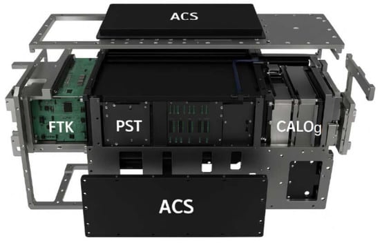
Figure 1.
Layout of the Ziré payload, excluding the LEM. From the left to the right: the Fiber Tracker (FTK), the Plastic Scintillator Tower (PST) and the Calorimeter (CALOg). A plastic scintillator AntiCoincidence System (ACS) envelopes the detector.
- flux and spectrum measurement of cosmic-ray electrons, protons and light nuclei up to 300 MeV of galactic and solar origin;
- measurement of gamma rays with energy below few tens of MeV, to study transient events, e.g., bright Gamma Ray Bursts, and Coronal Mass Ejections;
- space weather monitoring;
- spectrometry for electrons between 0.1 and 7 MeV and for protons between 3 and 50 MeV together with the LEM sub-detector, to investigate possible MILC couplings.
The axis of Ziré will be pointed towards the celestial horizon, along which three sub-detectors are aligned:
- the Fiber TracKer (FTK): it consists of three X-Y scintillating fiber modules, cross section, and it is designed to provide a fast and efficient trigger, to identify the particle entry point and measure the deposited charge;
- the Plastic Scintillator Tower (PST): it is a column of 32 layers, each one composed of three PS X–Y scintillator bars: the first six layers, i.e., those located immediately after the FTK, are thick, while the remaining 26 layers are thick. It provides a coarse tracking, energy measure and particle identification;
- the calorimeter (CALOg), consisting of a matrix of GAGG crystals, each with size . An entrance window on the FTK side ensures incoming particles go across the three sub-detectors; CALOg has two further windows, one facing the horizon and the other looking at the zenith, allowing measurement of energies below 10 MeV, typically gamma rays from transient events.
The Anti-Coincidence System (ACS), finally, consisting of nine layers of plastic scintillators, each 0.5 cm thick, cover the instrument on all sides except for the FTK entrance windows. It helps discriminate between events induced by charged particles and those generated by gamma rays. More details on the FTK design and on its characterization are given in the following text.
2. Materials and Methods
2.1. The Ziré FTK
The FTK consists of three modules spaced apart, each with two scintillating fiber planes arranged in orthogonal directions. Each plane consists of two staggered ribbons of Kuraray SCF78-MSJ double-cladding round fibers [8], as shown in Figure 2. Therefore, the on-axis thickness of an individual plane is about , allowing for a lower minimum energy threshold for particles to cross the three modules, reducing the multiple Coulomb scattering inside the module.
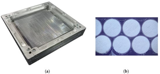
Figure 2.
Picture of one single X-Y module of the Ziré FTK (a), with a zoom on one side, in which the staggered structure of the Kuraray round fibers can be appreciated (b).
These scintillating fibers have a polystyrene core with a refractive index . A fluorescent dye is dissolved in the polystyrene matrix. The core is surrounded by a double cladding structure. The inner cladding is made of polymethylmethacrylate (PMMA) (), while the outer cladding is made of a fluorinated polymer (). Incident charged particles release an ionization energy deposit in the fiber, which is converted to optical photons (the light yield is approximately 8000 photons/MeV or more), which are transported by internal reflections to the light sensors located at the end of the fibers. The double cladding allows to enhance the trapping efficiency, which is about 5.4%, assuming that light propagates in the fiber via total internal reflections.
The FTK described above is based on detailed studies performed on reduced scale modules at Bari INFN laboratories [9,10,11]. They consisted of X-Y modules of two orthogonal planes of staggered round scintillating fibers, with cross section of , in order to match the size of the sensor used: a Hamamatsu S13552 MPPC SiPM array [12] of 128 channels. Individual cells have a size of , and are arranged in columns of pixels, resulting in a channel area of and a pitch of . The SiPM arrays were soldered on one side of a printed circuit board (PCB), and all channels are routed to four LSHM-120 Samtec multi-channel connectors [13] assembled on the other side of the PCB. To reduce the number of electronic channels, dedicated PCB interfaces were designed to group sets of two or four adjacent SiPM strips. Studies with different readout pitches (, and ) have been carried out, and study with fibers from two different producers (Kuraray and Saint Gobain) and two different diameters ( and ) have been also compared [14].
Since one side of the Ziré FTK is about long, 3 Hamamatsu SiPM arrays are needed to cover the whole side. They are mounted on a PCB, having 384 channels in total. Among the three modules, only the one closest to the PST has a double side readout, allowing to trigger with a left-right coincidence and reduce the redundancy. A custom electronic board has been developed, consisting of four FEBs hosting 6 CITIROC 1A [15] ASICs produced by OMEGA/Weeroc.
2.2. Zirettino Prototype
A reduced scale Ziré prototype has been assembled (see Figure 3) to validate the performance of the whole detector. In the following Table 1, the characteristics of each Zirettino sub-detectors are reported, compared to that of Ziré instrument.
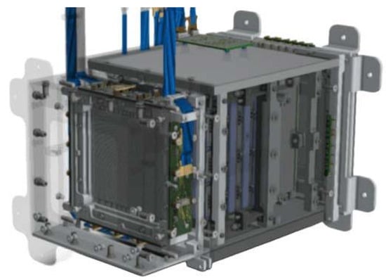
Figure 3.
A CAD image of the Zirettino, displaying the four PCBs of the FTK, equipped with SiPM arrays, and the SAMTEC cables.

Table 1.
Comparison between Ziré and Zirettino sub-detector sizes.
Focusing on FTK, Zirettino has only one module, designed by SOPHIA High Tech, based on FTK reduced prototypes. It is equipped with Kuraray scintillating fibers, with an equivalent readout pitch of . For the readout system, a prototype of the flying front-end board has been developed by Nuclear Instruments. It consists of a concentrator board hosting a central Field Programmable Gate Array (FPGA) and connected to a mezzanine board which is equipped with two DAQ-units. Each DAQ-unit hosts 4 Citiroc 1A ASICs, four LSHM-120 Samtec multi-channel connectors [13] and a Xlinx Artix UltraScale+ FPGA AU10P [16] for controlling the DAQ of the individual unit. Additionally, the board includes a number of NIM I/O connectors for the input and output of logical signals such as trigger and validation signals. For the readout of the whole prototype two FEBs are required, along with two concentrators and four DAQ units, and 16 ASICs (12 only for FTK). Different logic conditions have been implemented, including the FTK, the PST, and the CALOg. In particular, the FTK can provide a trigger to the other subsystem by requiring the coincidence of a signal on the same strip on both the right and left sides in both the X and Y views of the central section of the tracker. In order to take into account possible misalignment between the left and right sides of the same view the left-right coincidence request is implemented between pairs of adjacent strips.
3. Results
The FTK was characterized with a particle beam at CERN PS facility, and subsequently subjected to a qualification phase involving vibration and thermal tests. This section summarizes the results of these measurements. The goal of the beam test was the study of the performances in terms of efficiency and spatial resolution. Therefore, we selected particles with the maximum allowed beam momentum in the CERN-PS T10 beam line to minimize the multiple Coulomb scattering effects.
3.1. Characterization with the Data Collected During the Beam Test at CERN
The FTK of Zirettino was tested first at CERN PS facility with a 10 GeV/c negative pion beam. The first trigger level was provided by two modules of scintillators, choosing among square tiles, two fingers and one veto tile; the tracking system was obtained with two modules of the FTK reduced prototypes (described previously) placed upstream and downstream.
A particle traversing the FTK module usually results in a group of fired strips within each SiPM array: the charge distribution of those clusters in terms of photoelectrons (pe) averaged over the four SiPM arrays has been measured, giving a mean value of about 37 pe, as shown in Figure 4a.
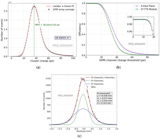
Figure 4.
(a) Distribution of photoelectrons into strip clusters, as the average charge among the four SiPM arrays of Zirettino FTK, fitted with a convolution of Landau and Gauss distribution. (b) The efficiency of the SiPM array connected to a given side as a function of the minimum number of photoelectrons () collected by the SiPM array. (c) Residual distribution fitted with a double Gaussian distribution (red curve). The two single Gaussian distribution are also reported in the plot (green and blue).
The capability of the FTK to provide a fast trigger to all other subsystems was also investigated. The trigger efficiency has been evaluated as a function of the charge collected by the hit strips, by imposing the condition that at least one strip is activated, with a charge above a certain threshold in each view (see Figure 4b). This efficiency depends clearly on the chosen threshold and increases as the threshold decreases, since more strips are likely to have a charge above that threshold. A plateau above 99% up to 15 p.e. has been observed.
Figure 4c shows the distributions of the residuals between the position of the particle reconstructed by the SiPM arrays of the FTK X view and the track determined with the external trackers. The distributions are peaked at zero but they have slight tails caused by multiple Coulomb scattering of charged particles with the atoms of the material on the beamline. The best fit curve is the sum of two Gaussian distributions with the same mean value but different sigma and amplitude. In this case, the resolution is determined from the combined widths of the two Gaussian functions and was evaluated from the FWHM of the best fit function. It can be observed that the spatial resolution found is of about . The values obtained are consistent with expectations.
The FTK of Zirettino has been tested also at CERN SPS facility. Lead ions with 150 A GeV/c momentum were sent on a Be target, and secondary nuclei with A/Z = 2 were selected. A preliminary joint analysis with PST has been performed in order to test the particle identification capability of the instrument [17]. Different ion species have been identified combining the information of the two detectors. Saturation effects of the SiPM and the electronics, and quenching effects in scintillators (Birks law), are evident for both FTK and PST, contributing to non-linearity effects.
3.2. FTK Qualification Tests
At the beginning of 2024 a Structural Model (SM) of Ziré was assembled by SOPHIA High Tech. It is completely equivalent to the Flight Model (FM) from the structural point of view, but the photodetectors and electronics modules were non-functional. It was assembled in order to evaluate its structural integrity during launch and operational conditions, by means of vibrational tests.
The SM fiber tracker comprised three modules: a first module with an epoxy glue layer (EPO-TEK 301) spread over the entire fiber plane, securing the fibers to the metal support across the entire surface of the module; a second module consisting of an empty frame; finally a module, the one closest to PST, with the epoxy glue layer over the fiber length and, additionally, two supports above and below the fiber mat to ensure the flatness of the module. These supports were realized from AIREX R21 (density of ), a material widely employed in aerospace applications due to its high mechanical strength combined with low density and good thermal insulation properties. It is a rigid foam made of polyvinyl chloride (PVC) characterized by a high resistance to mechanical stresses and by the capability of absorbing vibrations. The main goal was to compare these two designs, testing their robustness during dynamic tests, in order to define the best solution in terms of resistance and weight, while keeping the material budget minimal.
The Structural Model has been qualified with dynamic tests during Spring 2024 at Thales Alenia Space. Vibrations are generated using an electrodynamic shaker and their effects are measured through piezoelectric accelerometers placed at various positions on the object being tested. These accelerometers measure the acceleration experienced by the object along three directions and produce an electrical output signal that can be recorded and analyzed.
After the vibrational tests, a visual inspection showed no damage and all components kept the correct position. The two FTK modules of the SM were properly inspected (see left panel of Figure 5) and compared to a non-vibrated FTK module.
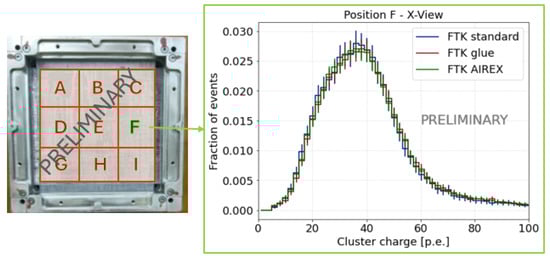
Figure 5.
Cluster charge distribution in the sector F of the three FTK modules: ‘FTK standard’ is the module with epoxy glue layer only between fiber ends and frame; ‘FTK glue’ represents the module with epoxy glue layer along all the fibers planes; ‘FTK AIREX’ indicates the module with AIREX supports.
The FTK module was divided in nine regions, labeled according to the scheme in the left panel of Figure 5, and tested at CERN PS beam test in late September 2024. Each of the three modules was placed on the beam line one at a time, with the quadrant under test positioned to ensure that the beam struck the central region. Data acquisition was controlled by an internal trigger generated by requiring coincidences on both the right and left sides in both views for the specific module section. An external tracking system provided a validation signal to discard events in which the signal was not generated by a beam particle. It can be observed that the FTK module not subjected to vibration shows the same cluster charge distribution, in terms of photoelectrons, compared to the other two modules. Therefore, no inefficiencies can be deduced, concluding that the FTK was not affected by any damage caused by vibrational tests.
4. Discussion
In spring 2025, three scintillating fiber modules were assembled in the clean room of the Bari INFN laboratories, following the design of the ’FTK glue’ module. These modules are designated for integration into the FTK of the Engineering Qualification Model (EQM), with functionality tests planned for early fall.
To evaluate potential deformations of the FTK fibers and mechanical structure caused by temperature variations expected during the mission, thermal tests were also carried out in Bari INFN laboratories during the summer 2025. The temperature range spanned from −30 ∘C to +45 ∘C, within the operational limits.
Near future activities include a vacuum test at fixed temperature, aimed at completing the FTK validation phase.
Finally, three modules for the flight model will be assembled in winter 2025. Delivery of the proto-flight model is expected in early 2026.
Author Contributions
Software, L.D.V., F.G., M.G., A.L., L.L., G.P. and R.P.; Validation, A.L., L.L., G.P. and R.P.; Investigation, F.C.T.B., G.F., M.G., A.L., F.L. (Francesco Loparco), L.L., M.N.M., G.P., R.P., P.S. and A.S.; Resources, G.D.R. and F.L. (Francesco Licciulli); Data Curation, M.G., A.L., L.L., G.P. and R.P.; Conceptualization, I.D.M., A.L., F.L. (Francesco Loparco), L.L., M.N.M., G.P. and R.P.; Methodology, A.L., F.L. (Francesco Loparco), L.L., M.N.M., G.P. and R.P.; Formal analysis, A.L., F.L. (Francesco Loparco), L.L., G.P. and R.P.; Writing—Original Draft, L.L. and G.P.; Supervision, M.N.M.; Project administration, M.N.M.; Funding acquisition, I.D.M., A.D.G. and M.N.M.; Writing—Review & Editing, A.L., L.L., M.N.M., R.P. and P.S. All authors have read and agreed to the published version of the manuscript.
Funding
This work is supported by the Italian Government (CIPE n. 20/2019), by the Italian Ministry of Economic Development (MISE reg. CC n. 769/2020), by the European Union NextGenerationEU under the MUR National Innovation Ecosystem grant ECS00000041-VITALITY-CUP D13C21000430001. This study was carried out also in collaboration with the Ministry of University and Research, MUR, under contract n. 2024-5-E.0-CUP n. I53D24000060005. This research, leading to the beam test results, also received partial funding from the European Union’s Horizon Europe research and innovation program under grant agreement No. 101057511.
Data Availability Statement
The datasets generated during and/or analyzed during the current studies are available from the corresponding author on reasonable request.
Acknowledgments
The authors would like to thank the INFN Bari staff for their contribution to the procurement and construction of the prototype. In particular, we are grateful to D. Dell’Olio, M. Franco, N. Lacalamita, F. Maiorano, M. Mongelli, C. Pastore, and R. Triggiani for their technical support. We also thank A. Abba and L. Ferrentino from Nuclear Instruments for their assistance with the readout boards, and D. Borrelli from Sòphia High Tech for his contribution to the mechanical design and development.
Conflicts of Interest
The authors declare no conflicts of interest.
References
- De Mitri, I.; Di Santo, M. The NUSES space mission. In Proceedings of the 12th Cosmic Ray International Seminar—CRIS, Napoli, Italy, 12–16 September 2022; Journal of Physics: Conference Series; IOP Publishing: Bristol, UK, 2023; Volume 2429, p. 012007. [Google Scholar]
- Aloisio, R.; Burmistrov, L.; Di Giovanni, A.; Heller, M.; Montaruli, T.; Trimarelli, C. The Terzina instrument on board the NUSES space mission. In Proceedings of the 38th International Cosmic Ray Conference (ICRC2023), Nagoya, Japan, 26 July–3 August 2023; Volume 444, p. 391. [Google Scholar]
- Montaruli, T. The Terzina payload on board the NUSES space mission. In Proceedings of the 39th International Cosmic Ray Conference (ICRC2025), Geneva, Switzerland, 15–24 July 2025. [Google Scholar]
- Abdullahi, M.; Aloisio, R.; Arneodo, F.; Ashurov, S.; Atalay, U.; Barbato, F.C.T.; Battiston, R.; Bertaina, M.E.; Bissaldi, E.; Boncioli, D.; et al. The Zirè experiment on board the NUSES space mission. In Proceedings of the 39th International Cosmic Ray Conference (ICRC2025), Geneva, Switzerland, 15–24 July 2025. [Google Scholar]
- Panzarini, G. The Zirè detector on board the NUSES space mission. In Proceedings of The XIII International Conference on New Frontiers in Physics, Orthodox Academy of Crete, Kolymbari, Crete, Greece, 17–31 July 2025. [Google Scholar]
- Piersanti, M.; Materassi, M.; Battiston, R.; Carbone, V.; Cicone, A.; D’Angelo, G.; Diego, P.; Ubertini, P. Magnetospheric–Ionospheric–Lithospheric Coupling Model. 1: Observations during the 5 August 2018 Bayan Earthquake. Remote Sens. 2020, 20, 3299. [Google Scholar] [CrossRef]
- Abdullahi, M.; Aloisio, R.; Arneodo, F.; Ashurov, S.; Atalay, U.; Barbato, F.C.T.; Battiston, R.; Bertaina, M.E.; Bissaldi, E.; Boncioli, D.; et al. Online Time and Energy Resolved Flux Measurements of sub-MeV Charged Particles with the Zirè Low Energy Module (LEM) on the NUSES Space Mission. In Proceedings of the 39th International Cosmic Ray Conference (ICRC2025), Geneva, Switzerland, 15–24 July 2025. [Google Scholar]
- Plastic Scintillating Fibers. Available online: http://kuraraypsf.jp/pdf/all.pdf (accessed on 2 September 2025).
- Mazziotta, M.N.; Altomare, C.; Bissaldi, E.; De Gaetano, S.; De Robertis, G.; Dipinto, P.; Di Venere, L.; Franco, M.; Fusco, P.; Gargano, F.; et al. A light tracker based on scintillating fibers with SiPM readout. Nucl. Instruments Methods Phys. Res. Sect. A 2022, 1039, 167040. [Google Scholar] [CrossRef]
- Mazziotta, M.N.; Pillera, R. The light tracker based on scintillating fibers with SiPM readout of the Zirè instrument on board the NUSES space mission. In Proceedings of the 38th International Cosmic Ray Conference (ICRC2023), Nagoya, Japan, 26 July–3 August 2023; Volume 444, p. 83. [Google Scholar]
- Mazziotta, M.N.; Pillera, R. Development of a light tracker based on thin scintillating fibers and Silicon Photomultipliers for space application. Nucl. Instruments Methods Phys. Res. Sect. A 2025, 1882, 171064. [Google Scholar]
- Hamamatsu S13552 MPPC. Available online: https://www.hamamatsu.com/jp/en/product/optical-sensors/mppc/mppc_mppc-array/S13552.html (accessed on 2 September 2025).
- Razor beam LSHM-120 Connector. Available online: https://www.samtec.com/products/lshm (accessed on 2 September 2025).
- Pillera, R.; Altomare, C.; De Robertis, G.; Di Venere, L.; Gargano, F.; Giliberti, M.; Loparco, F.; Loporchio, S.; Lorusso, L.; Panzarini, G.; et al. Characterization of a light fiber tracker prototype with SiPM array readout. In Proceedings of the 2023 9th International Workshop on Advances in Sensors and Interfaces (IWASI), Monopoli, Italy, 8–9 June 2023; pp. 221–226. [Google Scholar]
- Citiroc 1A ASIC. Available online: https://www.weeroc.com/read_out_chips/citiroc-1a/ (accessed on 2 September 2025).
- AMD Artix UltraScale+ FPGAs. Available online: https://www.amd.com/en/products/adaptive-socs-and-fpgas/fpga/artix-ultrascale-plus.html (accessed on 11 November 2025).
- Pillera, R. Nuses CollaborationThe scintillating fiber tracker of the Ziré detector on the NUSES space mission. J. Instrum. 2024, 19, C11005. [Google Scholar] [CrossRef]
Disclaimer/Publisher’s Note: The statements, opinions and data contained in all publications are solely those of the individual author(s) and contributor(s) and not of MDPI and/or the editor(s). MDPI and/or the editor(s) disclaim responsibility for any injury to people or property resulting from any ideas, methods, instructions or products referred to in the content. |
© 2025 by the authors. Licensee MDPI, Basel, Switzerland. This article is an open access article distributed under the terms and conditions of the Creative Commons Attribution (CC BY) license (https://creativecommons.org/licenses/by/4.0/).