Abstract
The purpose of this paper is to investigate the through-thickness stresses of woven glass fiber reinforced polymer (GFRP) composite laminates under combined tensile and shear loading. Tensile tests were carried out with cross specimens at room temperature under various stacking angles, and the through-thickness strength properties of the woven GFRP laminates were evaluated. The failure characteristics of the woven GFRP laminates were also studied by optical microscopy observations. A three-dimensional finite element analysis (FEA) was carried out to calculate the stress distributions in the cross specimens, and the failure conditions of the specimens were examined. The numerically determined interlaminar tensile and shear stresses at failure location were consistent with Hoffman and Mohr-Coulomb failure criteria when the stacking angle was relatively small. This work is the first attempt to quantify the relation between interlaminar tensile and shear strengths of GFRP composite laminates under tensile and shear loading simultaneously using a combined numerical and experimental approach. A method based on finite element stress analysis was developed for estimating the through-thickness strength of the composite laminates using the experimentally determined fracture load and location. The results suggest that the through-thickness strength under combined tensile and shear loading can be determined effectively by this approach for relatively small stacking angles.
1. Introduction
Woven glass fiber reinforced polymer (GFRP) composite laminate is applied in various fields because of its excellent mechanical and physical properties. In this laminate, interlaminar failure is one of the most critical failure modes; therefore interlaminar mechanical properties can govern the design of composite structures. Up to now, many studies have been performed regarding interlaminar shear properties of woven composite laminates. For example, Takeda et al. [1] have examined the shear strength and damage self-sensing of woven carbon fiber reinforced polymer (CFRP) composite laminates at cryogenic temperatures. They have revealed that the apparent interlaminar shear strength of woven CFRP composite laminates decreases with decreasing from room temperature to cryogenic temperatures. Cai et al. [2] have investigated the effect of through-thickness compressive stress on the fiber direction tensile strength of GFRP composite laminates. They have demonstrated a nonlinear decreasing trend for the in-plane tensile strength under the growing through-thickness compressive stress in GFRP with a random oriented mat of glass fibers. Gan et al. [3] have shown that the fiber-direction (longitudinal) tensile strength of CFRP composite laminates decreases with increasing through-thickness compressive stress. Recently, the interlaminar tensile strength of woven composite laminates has been studied. The ASTM standard test method [4] is used to determine the through-thickness tensile strength and elastic modulus of fiber reinforced polymer composite materials. In this method, a tensile force is applied using adhesively bonded thick metal end tabs. However, since the bond strength of the adhesive may be lower than the through-thickness strength of the composite laminates, the failures at the adhesive layer between the composite specimen and the end tabs is one of the drawbacks of this test method. Gerlach et al. [5] proposed a cross specimen to characterize the through-thickness tensile properties of three-dimensional (3D) woven CFRP composite laminates. Takeda et al. [6] have also proposed another cross specimen to investigate the interlaminar tensile behavior of woven GFRP composite laminates at cryogenic temperatures. The dimensions of the cross specimen were designed by performing 3D finite element analysis (FEA). Static through-thickness tensile tests were performed on woven GFRP composite laminates using this cross specimen, and the interlaminar tensile failure mechanisms were investigated. This study demonstrated that the specimen is suitable for obtaining the through-thickness tensile strength data. Hoffmann et al. [7] have proposed a new specimen geometry to determine the through-thickness tensile strength of composite laminates, based on FEA and the test results. Narita et al. [8] actually adopted the geometry [6] and performed cyclic fatigue through-thickness tensile tests on the cross specimen of woven GFRP composite laminates at cryogenic temperatures, and investigated the interlaminar tensile fatigue mechanisms. It was found that cooling from room temperature to 77 K causes an increase in the number of cycles to failure.
As mentioned above, a variety of research on the interlaminar properties of woven composite laminates has been conducted. However, the combined interlaminar tensile and shear behavior has still not been evaluated enough even though the actual material failure involves interlaminar tensile and shear stresses simultaneously.
In this study, we performed static through-thickness tensile tests on the cross specimens of woven GFRP composite laminates with various stacking angles () at room temperature, and evaluated the combined interlaminar tensile and shear properties. The failure characteristics of the specimens were also observed by optical microscopy. In addition, the stress distributions in the cross specimen and the failure conditions of the specimens were calculated by the FEA.
2. Experiment Procedure
2.1. Materials
National Electrical Manufacturers Association (NEMA) grade G-11 commercial plain woven GFRP composite laminates (Toyo Lite Co., Ltd., Kyoto, Japan) were prepared. The fibers were E-glass, and the woven fabric used in the G-11 woven laminates was a plain weave consisting of warp and fill bundles interlaced orthogonally. The fibers were sized with epoxy and silane. The matrix was bisphenol-A epoxy resin cured with 4,4’-diaminodiphenyl sulfone (DDS) hardener, its specific density was 1.8 and the overall fiber weight fraction was approximately 60 wt.%. The manufacturer denotes the standard strengths of this material in accordance with each applicable JIS standard (JIS K-6911). These values are shown below. The flexural strengths: 350 MPa (vertical to lamination) and 250 MPa (parallel to lamination). The compressive strengths: 350 MPa (vertical to lamination) and 250 MPa (parallel to lamination). The tensile strength: 200 MPa.
Figure 1 shows the schematic illustration of the cross specimen. The dimensions of the cross specimen were width mm, shoulder radius mm, thickness of the reduced section mm, thickness and length of the crossing beam section mm and mm, respectively. Total thickness of the specimen was mm. In order to investigate the behavior of the laminates subjected to the combined interlaminar tensile and shear stresses, the stacking angles for the horizontal plane in each specimen were varied (). The specimen at stacking angle is shown in Figure 2. The global coordinate system - was defined at the center position of the specimen, and the -axis was set to be parallel to the through-thickness direction. The aforementioned horizontal plane corresponded to the -plane. These cross specimens were produced by cutting a thick plain woven GFRP panel set at a predetermined angle by a milling machine. The cross specimen was designed based on the data calculated by the FEA [6]. It was expected to produce a desirable failure mode because the through-thickness tensile stress distribution was maximized in the edge of the central reduced section. Then, it is possible to obtain reliable interlaminar strength data.
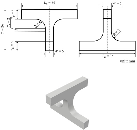
Figure 1.
Schematic of cross specimen.
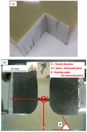
Figure 2.
(a) The glass fiber reinforced polymer (GFRP) composite laminates and (b) detailed description of the cross specimen with stacking angle .
2.2. Instrumentation
Figure 3 shows the experimental setup for the combined interlaminar tensile and shear test. The cross specimen was supported and loaded at two points, respectively, and the loading and support spans, weremm. These test jigs were made of SUS 304 austenitic stainless steel, and each diameter was 10 mm. In this condition, the reduced section in the center can be subjected to a tensile load. When using the cross specimen having different stacking angles (i.e.,, both an interlaminar tensile stress and an interlaminar shear stress were generated in the fiber/matrix interface.
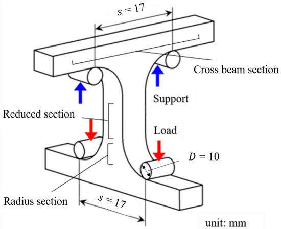
Figure 3.
Setup of combined interlaminar tensile and shear test.
The combined interlaminar tensile and shear tests were performed at room temperature. A servo-hydraulic testing machine (EHF-UB30KN-20LA, Shimadzu Co., Japan) was used as the loading machine. The cross specimens were loaded under displacement control with 0.1 mm/min, and it secured a static loading condition [4]. In each test, the load and load point displacement were recorded using a general-purpose data acquisition system (NR-500 series, Keyence Co., Osaka, Japan). At least six experiments were performed under each condition except . It should be noted that strain measurements, using the strain gauges, were not carried out because of the non-uniform stress/strain fields in the central reduced section [6].
After the tests, the microscopic examinations of the specimens were performed using optical microscopy (VHX-500 and VH-Z05, Keyence Co., Osaka, Japan). Then, the fracture behavior was observed, and the fracture angles for the horizontal plane (-plane) were measured.
2.3. Finite Element Analysis
A 3D FEA was performed on the cross specimens with various stacking angles using ANSYS Multiphysics code (ver. 11.0). Figure 4 shows the finite element model of the cross specimen and the test jigs. The global coordinate system was defined as a Cartesian coordinate system O- with the -axis being parallel to the through-thickness direction of the specimen. The origin of the global coordinate system was located at the center of the cross specimen.
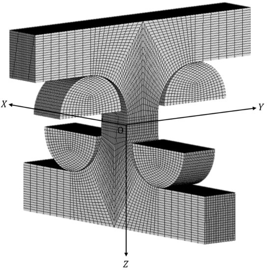
Figure 4.
Finite element model of cross specimen.
The woven GFRP laminates were modeled as one homogeneous orthotropic elastic material, and the test jigs were modeled as an extremely stiff elastic body. When the stacking angle was not parallel or perpendicular to the horizontal plane, the material properties of the cross specimen were asymmetric. Therefore, the local coordinate systems of the specimen were defined as a Cartesian coordinate system o-. The origin of the local coordinate systems was also located at the centers of each element. In order to consider the stacking angles of each specimen, the local coordinate systems were rotated around the -axis by an appropriate angle based on the following equation:
The schematic of the geometric relationship is shown in Figure 5. The -, - and -axes were, respectively, along the warp, fill, and through-thickness direction of each specimen.
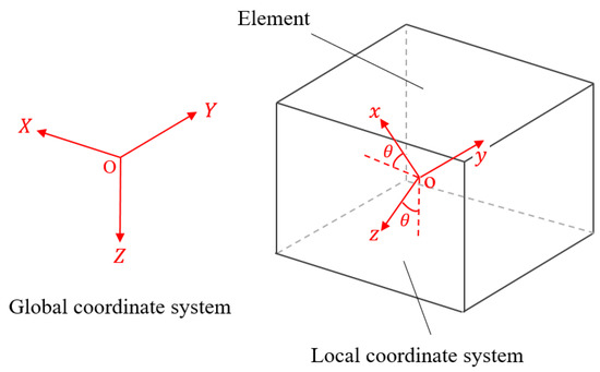
Figure 5.
Schematic of geometric relationship.
The constitutive equations according to the local coordinate systems can be written by the following equation:
where are the strain components, are the stress components, are the Young’s moduli, are the shear moduli, and are the Poisson’s ratios (). is the Poisson’s ratio for transverse strain in the -direction when stressed in the -direction, and a similar convention can be used for the other Poisson’s ratios and .
The orthotropic elastic properties of the G-11 woven GFRP laminates for the FEA of the cross specimens were determined from the micromechanics model for composites reinforced with plain weave fabrics [9]. The model included some parameters to characterize the fabric microstructures and the constituent material properties (i.e., Young’s moduli, Poisson’s ratios, and shear moduli). The parameters of the G-11 woven GFRP laminates at room temperature (295K) are given in Table 1 [6,10].

Table 1.
The material properties of G-11 woven GFRP laminates at room temperature.
The mechanical loadings are produced by applying the prescribed displacement, in the -direction on the top surface of the loading noses. Then, the displacements are adjusted so that the total nodal forces on the top surface of the loading noses correspond to the average fracture loads, for each stacking angle obtained from the experiments. On the other hand, the supporting jigs are fixed.
Eight-node 3D solid elements were applied for meshing the specimen and the jigs. The model consisted of 178,473 nodes and 174,880 elements.
In the analysis, the interlaminar stress distributions were calculated. Considering the experimental results, the interlaminar tensile strength and shear strengthwere also obtained. Finally, the relationship between the fracture interlaminar tensile and shear stresses was compared to the Hoffman failure criterion [11]. Considering the uniaxial tensile, compressive stresses and shear stress , we have
where and are the tensile, compressive and shear strengths. The subscripts andrepresent the tensile, compression and shear. The relationship between the fracture interlaminar tensile and shear stresses was also compared to the following Mohr–Coulomb theory [12]:
Takagi et al. [13] and Kitamura et al. [14] have applied the above criterion to the slip behavior and debonding behavior of the laminates.
3. Results and Discussion
3.1. Combined Interlaminar Tensile and Shear Tests
Figure 6 shows the failure cross specimens for each stacking angle after the combined interlaminar tensile and shear tests. Red dashed line means the fracture part. Table 2 lists typical fracture stress, fracture angle, and fracture location obtained from each test. Only data for the specimens fractured at the part surrounded by the red line (see Figure 6) are reported. It was found that all cross specimens fractured along each stacking angle. In addition, the cross specimens with stacking angles fractured near the reduced section. Some specimens with the stacking angle of tended to fracture at radius points, while others fractured near the loading points. In the case of the stacking angle , all specimens fractured near the loading points. Because the complex stress distributions and the stress concentrations occur near the contact points between the specimen and the jigs, there is a possibility that the fracture data of the specimens with the stacking angles of and were incorrect. Therefore, the data of the specimens that fractured near the loading points were not employed.

Figure 6.
Failed cross specimens for each stacking angle : (a) , (b) , (c) , (d) , and (e) .
Table 2.
Typical fracture stress, fracture angle and fracture location of cross specimens.
Figure 7 shows the typical stress-displacement curves of the cross specimens for each stacking angle. It was confirmed that the fracture stress increased as the stacking angle increased. This is because the fibers were more oriented in the tensile direction with an increase in the stacking angle. Furthermore, we suggest that the elongation increases until the stacking angle of, and then decreases at.
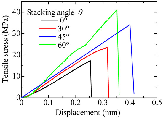
Figure 7.
Stress–displacement curves of cross specimens for each stacking angle.
3.2. Finite Element Analysis
Figure 8 shows the distributions of the normal stress and strain in the Z-direction in the global coordinate system, and interlaminar tensile and shear stresses in the local coordinate system for the specimen with the stacking angle of . It seems that the normal stress and strain are uniform in the reduced section. Note that the shear stresses in the global coordinate system are almost zero (no figure shown). Therefore, in order to discuss the through-thickness strength under combined tensile and shear loading, it is necessary to evaluate the stresses in the local coordinate system (see Figure 8c,d), Figure 9 also shows the stress distributions along the path with X = −2.5 mm, Y = 0 mm, Z = 0 Z 7 mm under the fracture stress . In this figure, denotes the through-thickness tensile stress, and and indicate the interlaminar tensile and shear stresses, respectively. It was shown that the combined interlaminar stress fields were generated near the fracture locations of the cross specimens when the stacking angle was not equal to . If the stacking angle was less than , the fibers were substantially oriented perpendicular to the tensile direction. Hence, the tensile strength of the fiber/matrix interface contributes to the fracture strength of the specimen. Considering that the specimens with the stacking angles of and fractured at the reduced section (see Table 2) where the interlaminar tensile stress was maximum, it was confirmed that the contribution of the interlaminar tensile stress was dominant regarding the specimen failure among the combined interlaminar stress fields when the stacking angle was low. On the other hand, if the stacking angle was or more, the interlaminar shear strength contributed to the fracture strength. In this case, the fibers were more oriented in the tensile direction. The through-thickness strength of the specimen increased, and the effect of the interlaminar shear stress on fracture increased relative to the interlaminar tensile stress. From the results shown in Table 2 and Figure 9, the specimens with the stacking angles and fractured near the section where the interlaminar shear stress reached a peak. Therefore, it was found that the contribution of the interlaminar shear stress was dominant with regard to the failure among the combined interlaminar stress fields when the stacking angle was high. However, there is the possibility that the specimens which fractured near the loading points cannot be correctly considered because very complex stress fields were generated. From these results, it is possible to determine the fracture interlaminar tensile and shear stresses of the specimens which fractured near the reduced sections. Here, these calculated fracture interlaminar tensile and shear stresses in Figure 9 are regarded as the interlaminar tensile and shear strengths.
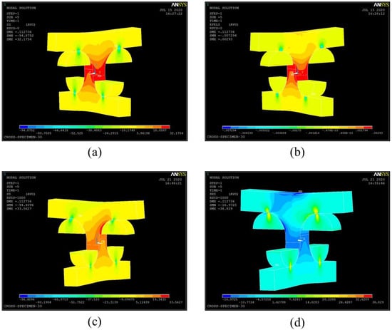
Figure 8.
The distributions of the (a) normal stress and (b) normal strain in the Z-direction in the global coordinate system, and (c) interlaminar tensile and (d) interlaminar shear stresses in the local coordinate system (stacking angle
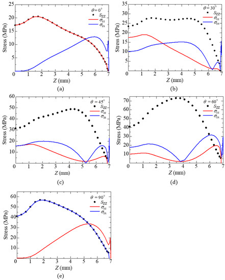
Figure 9.
Stress distributions along the path with X = −2.5 mm, Y = 0 mm, Z = 0 Z 7 mm under fracture stress for each stacking angle : (a) , (b) , (c) , (d) , and (e) . ().
Figure 10 shows the relationship between the values of interlaminar tensile strength and shear strength of each specimen. In this figure, the interlaminar stress values for the specimens fractured at loading point are omitted. The dashed black line shows the prediction from Equation (3) whereas solid red line represents the one from Equation (4). Here, and were obtained from the experiments [6,15]. The value of was assumed to be the compressive strength of SL-ES30 woven GFRP composite laminate at room temperature [16]. Three important observations can be made based on the data. First, from this result, it can be seen that the interlaminar tensile strength was decreased while the interlaminar shear strength was increased as the stacking angle increased. Second, good agreement between the two theories was found. This is due to the fact that Equation (3) can be approximated by Equation (4) when the compressive strength is much larger than the tensile strength . Third, the experimental values for were not consistent with the theoretical ones, because the maximum interlaminar shear stress is applied in the radius section. This finding indicated that the interlaminar fracture behavior of the woven GFRP composite laminates under combined tensile and shear loadings could be predicted correctly by using the theoretical failure criteria for the stacking angles of , and . For the stacking angle of , it is necessary to design a new cross specimen geometry. Work in this area is currently being pursued.
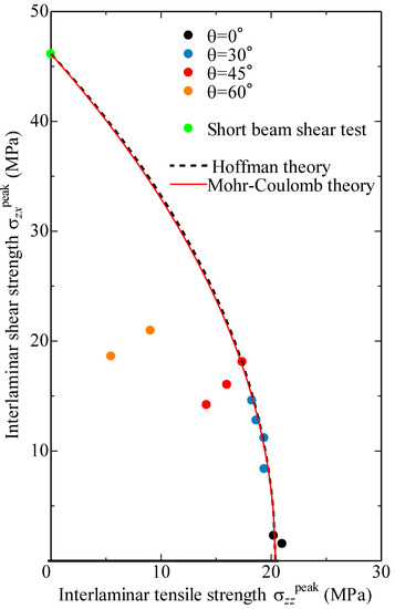
Figure 10.
Relationship between interlaminar tensile strength and shear strength .
4. Conclusions
In this study, the combined interlaminar tensile and shear tests and the numerical simulations by FEA were conducted. By introducing local coordinate systems, the peak interlaminar tensile and shear stresses at the fracture locations were estimated, and these values could be regarded as the interlaminar tensile and shear strengths. Then, the following conclusions are drawn as:
- The cross specimens with the stacking angles tended to fracture near the reduced section, whereas some specimens with stacking angle fractured at the radius point where the maximum interlaminar shear stress would be applied, and all specimens with the stacking angle fractured near the contact points between the specimen and the jigs where the stress concentration occurred.
- From the predicted interlaminar stress distributions obtained by FEA, it was found that the combined interlaminar tensile and shear stress fields were generated in the reduced sections of the specimens with the stacking angles and .
- Considering the predicted interlaminar stresses at fracture locations calculated by FEA, it was confirmed that the interlaminar tensile strength decreased while the interlaminar shear strength increased as the stacking angle increased. Furthermore, the relationship between the combined interlaminar tensile and shear strengths obtained from FEA were actually almost consistent with the prediction based on Hoffman and Mohr-Coulomb failure criteria when the stacking angle was , and .
- We derived the tensile and shear strengths from the FEA with stacking angle and reference data [16] of the short beam shear test, respectively, and these values were determined by = 20.4 MPa and = 46.1 MPa. On the other hand, from this study, the interlaminar tensile and shear strengths of the GFRP composite laminates with each stacking angle were expected at = 19.2 MPa, = 11.1 MPa, = 17.5 MPa, = 14.4 MPa and = 25.0 MPa, respectively.
The current approach provides a reasonable estimation of the through-thickness strength of the woven composite laminates under combined tensile and shear loading for the stacking angles , and . Future work will be focused on the improvement of the strength evaluation for the stacking angle by changing the geometry of the cross-specimen.
Author Contributions
Conceptualization, F.N.; methodology, F.N.; validation, T.K. and H.K.; formal analysis, T.K. and M.S.; investigation, T.K. and M.S.; data curation, T.K. and M.S.; writing—original draft preparation, T.K. and M.S; writing—review and editing, H.K. and F.N.; visualization, T.K. and M.S.; supervision, F.N.; project administration, H.T. All authors have read and agreed to the published version of the manuscript.
Funding
This research received no external funding.
Conflicts of Interest
The authors declare no conflict of interest.
References
- Takeda, T.; Shindo, Y.; Fukuzaki, T.; Narita, F. Short beam interlaminar shear behavior and electrical resistance-based damage self-sensing of woven carbon/epoxy composite laminates in a cryogenic environment. J. Compos. Mater. 2014, 48, 119–128. [Google Scholar] [CrossRef]
- Cai, D.; Zhou, G.; Silberschmidt, V. Effect of through-thickness compression on in-plane tensile strength of glass/epoxy composites: Experimental study. Polym. Test. 2016, 49, 1–7. [Google Scholar] [CrossRef][Green Version]
- Gan, K.W.; Wisnom, M.R.; Hallett, S.R. Effect of high through-thickness compressive stress on fiber direction tensile strength of carbon/epoxy composite laminates. Compos. Sci. Technol. 2014, 90, 1–8. [Google Scholar] [CrossRef]
- ASTM D7291/D7291M-07. Standard Test Method for Through-Thickness “Flatwise” Tensile Strength and Elastic Modulus of A Fiber-Reinforced Polymer Matrix Composite Material; Annual Book of Standards; ASTM International: West Conshohocken, PA, USA, 2007.
- Gerlach, R.; Siviour, C.R.; Wiegand, J.; Petrinic, N. In-plane and through-thickness properties, failure modes, damage and delamination in 3D woven carbon fiber composites subjected to impact loading. Compos. Sci. Technol. 2012, 72, 397–411. [Google Scholar] [CrossRef]
- Takeda, T.; Narita, F.; Shindo, Y.; Sanada, K. Cryogenic through-thickness tensile characterization of plain woven glass/epoxy composite laminates using cross specimens: Experimental test and finite element analysis. Compos. Part B 2015, 78, 42–49. [Google Scholar] [CrossRef]
- Hoffman, M.; Zimmermann, K.; Bautz, B.; Middendorf, P. A new specimen geometry to determine the through-thickness tensile strength of composite laminates. Compos. Part B 2015, 77, 145–152. [Google Scholar] [CrossRef]
- Narita, F.; Tanaka, C.; Suzuki, M. Interlaminar tension-tension fatigue of woven glass fiber reinforced plastic composite laminates at low temperatures. J. Compos. Biodegrad. Polym. 2018, 6, 28–33. [Google Scholar] [CrossRef]
- Hahn, H.T.; Pandey, R. A micromechanics model for thermoelastic properties of plain woven fabric composites. J. Eng. Mater. Technol. 1994, 116, 517–523. [Google Scholar] [CrossRef]
- Miura, M.; Shindo, Y.; Takeda, T.; Narita, F. Interlaminar fracture characterization of glass/epoxy composites under mixed-mode II/III loading conditions at cryogenic temperatures. Eng. Fract. Mech. 2012, 96, 615–625. [Google Scholar] [CrossRef]
- Hoffman, O. The brittle strength of orthotropic materials. J. Compos. Mater. 1967, 1, 200–207. [Google Scholar] [CrossRef]
- Chen, W.F. Limit Analysis and Soil Plasticity; Elsevier Scientific Publishing Company: New York, NY, USA, 1975. [Google Scholar]
- Takagi, T.; Miya, K.; Takeuchi, Y.; Tani, J. Unite element slip analysis of multi layer beam plate based on a composite theory. Fusion Eng. Des. 1989, 7, 255–267. [Google Scholar] [CrossRef]
- Kitamura, K.; Yamamoto, T.; Uchida, T.; Moriyama, H.; Yamamoto, J.; Nishimura, A.; Motojima, O. Cryogenic shear fracture tests of interlaminar organic insulation for a forced-flow superconducting coil. IEEE Trans. Magn. 1994, 30, 1879–1882. [Google Scholar] [CrossRef]
- Miura, M.; Shindo, Y.; Takeda, T.; Narita, F. Effect of damage on the interlaminar shear properties of hybrid composite laminates at cryogenic temperatures. Compos. Struct. 2010, 93, 124–131. [Google Scholar] [CrossRef]
- Shindo, Y.; Tokairin, H.; Sanada, K.; Horiguchi, K.; Kudo, H. Compression behavior of glass-cloth/epoxy laminates at cryogenic temperatures. Cryogenics 1999, 39, 821–827. [Google Scholar] [CrossRef]
© 2020 by the authors. Licensee MDPI, Basel, Switzerland. This article is an open access article distributed under the terms and conditions of the Creative Commons Attribution (CC BY) license (http://creativecommons.org/licenses/by/4.0/).