Abstract
Twin-roll casting is a technology for the production of thin strips directly from liquid metal by combining continuous casting with hot rolling in a single step. The thermo-mechanical cyclic interaction with the solidifying strip causes fatigue crack formation at the outer surface of the rolls. A 2D FEM model with Eulerian boundary conditions and the interference fit load on the rolls was defined. The influence of the roll–strip thermal contact, the inlet temperature of the liquid aluminum, the efficiency of the water cooling and the production rate on the fatigue damage of the rolls was analyzed with a parametric study. The maximum temperature of the rolls, the maximum contact pressure, the accumulated plastic strain and the equivalent strain computed (considering a multiaxial out-of-phase fatigue criterion) were considered to investigate the thermo-mechanical fatigue load on the rolls. The results showed that, in the considered range, the most influential parameters on the fatigue mechanism are the heat contact conductance coefficient, which dominates the thermo-mechanical load, and the tangential velocity of the rolls, which contributes to the thermal field and determines the roll–strip mechanical contact interaction.
1. Introduction
Twin-roll casting is a technology for the production of thin strips about 1 mm to 10 mm thick. The process was devised by Henry Bessemer [1] and involves the production of the strips directly from liquid metal by combining continuous casting with hot rolling in a single step. The operating principle is based on the rapid solidification of the liquid metal on internally cooled rotating rolls and on the mechanical action of these rolls on the strip [2,3]. Compared to the more traditional processes [4], twin-roll casting allows a reduction in production steps, energy savings and lower investment costs [5], while also allowing for recycled materials [6]. The microstructure and mechanical properties of the finished product are also considerable [7,8,9] and are still the object of research [10,11,12,13].
There are three main types of twin-roll casting according to the direction of the molten metal flow: horizontal, with the axes of the rolls arranged vertically one above the other [14]; vertical, with the axes on the horizontal plane [15]; and an inclined configuration [7].
The operating conditions of the rolls depend on thermal factors, fluid dynamics and mechanical interactions between the rolls and the strip [16]. The main parameters that influence these aspects are the superheat temperature of the melted metal, the configuration of the nozzle, the presence or absence of lubricant between the rolls and the strip, the thickness of the strip, the rotation speed of the rolls, heat and force exchanged (roll separation force) between the rolls and the strip [17], the rolls’ material (steel or copper) and their diameter.
There have been several studies that carry out a thermo-fluid dynamic analysis of the process, often performed by a numerical method with 2D or 3D models [18]. The models have investigated the solidification of the metal, distinguishing the liquid, solid and an intermediate liquid–solid zone (mushy zone) and identifying turbulent flows in the molten area [19]. The amplitude of the mushy zone influences the mechanical force exchanged between the rolls and the strip and the properties of the product [20]. The proposed models take into account possible turbulence, solidification, thermal fluxes to the environment and the heat exchange between the rolls and the strip, identifying the heat transfer coefficient as one of the most important parameters [21]. From a fluid dynamics point of view, the liquid–solid strip can be represented as a mono-phase or bi-phase material, modeling the semi-solid area (mushy zone) like a substance with variable viscosity [22,23,24].
Studies relating specifically to the analysis of stresses and strains in the twin-roll casting process, on the other hand, seem to be few and not easily available, and they mainly concern the strip produced [12].
The wear of the rolls in the twin-roll casting process of steel was experimentally studied by Zapuskalov et al. [25], investigating the surface roughness of the roll and showing the influence of the erosive action due to the flow of processed material on the component.
Stress analysis in both the strip and rolls was studied by Saxena et al. [26]. Stresses due to friction between the rolls and the strip were not considered, and the roll separating force was calculated analytically and then applied on the components. The liquid–solid metal was modeled as a viscoplastic material by adjusting the Poisson coefficient and the Young modulus to treat the liquid. The analysis showed the arising of high compression stresses on the surface of the roll due to thermal load and compression force on the rolls, identifying the conditions for the onset of fatigue.
Hadadzadeh et al. [20] developed a 2D model of the top-half part of the group roll/strip. The solidification process and the zone of liquid–solid transition (mushy zone) were taken into consideration. The rolls were assumed to be rigid and the interaction between the roll and the strip was modeled considering the friction according to Coulomb’s law.
The influence on the interaction force between the strip and the rolls, the asymmetrical rotation speed of the rolls and the configuration of the nozzle has been studied by Lee et al. [16]. The values obtained from the numerical simulation were compared with the force values measured experimentally, showing the convergence of the respective values over time.
The twin-roll casting process has received a growing interest in recent decades. The parameters of the process and their influence on the product have been studied, but not much has been carried out to specifically analyze the conditions of the rolls. The objective of this work is to study the thermo-mechanical state and the damage conditions in relation to the rolls’ life expectancy in the twin-roll casting process of aluminum alloys.
Rolls are an important component, not only for their cost, but also for the required reliability necessary to ensure the continuous productivity of the process.
Due to the thermo-mechanical conditions at the outer surface of the roll, wear damage occurs and cracks form [27]. These cracks can generate defects and determine the production of a low-quality strip. The propagation of the cracks can cause the failure of the roll [28]. To avoid the failure of the rolls and to ensure a good-quality product, it is important to perform roll maintenance operations. Hence, it is necessary to investigate the damaging phenomena at the outer surface of the rolls by considering different operating conditions.
This is possible by developing a thermo-mechanical numerical model of the rolls to predict their stress and strain state during the process. In order to investigate the damage phenomena and to predict the crack initiation, the influence of the main process parameters is considered. A proper fatigue index is considered to compare the expected damage in different process conditions.
2. Materials and Methods
A 2D schematic of the horizontal twin-roll thin-strip caster with all dimensions is illustrated in Figure 1. The geometrical data taken into account are shown in Table 1.
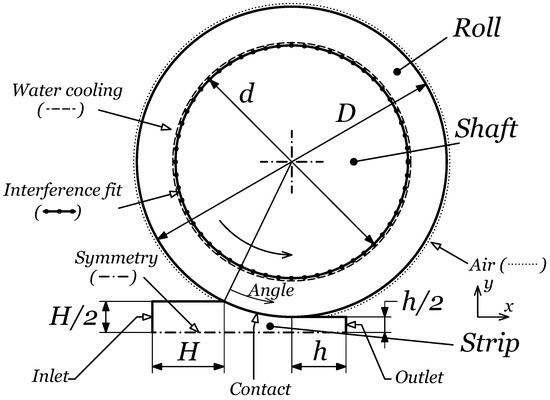
Figure 1.
Schematic representation of the twin-roll casting process with relevant modeling parameters.

Table 1.
Geometrical data of the roll and the strip.
An explicit thermo-mechanical 2D plane-strain FEM was defined by using Abaqus 2020 FEA software. The symmetry of the problem was considered and the top-half part of the strip–roll–shaft geometry was modeled. Lagrangian analysis was used, but the Eulerian boundary conditions [29] at the inlet and the outlet zones were imposed. This allowed us to model a limited portion of the strip during the whole simulation and to avoid unwanted mesh deformations. To reach the steady-state conditions during the process while considering the time cost of the numerical simulation, 8 rotations of the rolls were performed. The attainment of the steady-state conditions was verified a posteriori by considering the thermo-mechanical state history of the rolls during the simulations.
The reference conditions for the simulation were considered as follows: , , and . Then, a parametric study was performed by varying 4 process parameters through 5 levels:
- Strip–roll contact conductance coefficient, , which represents the thermal efficiency of the heat-removing process from the strip during the production;
- The liquid aluminum superheat, , related to the initial temperature of the liquid aluminum poured though the nozzle between the rolls;
- Water-cooling heat transfer coefficient, , related to the intensity and efficacy of the cooling system at the internal surface of the rolls;
- The tangential velocity of the rolls, , representing (and proportional to) the production rate of the finite product.
To analyze the impact of the process conditions on the thermo-mechanical load and fatigue, 4 indicators were considered:
- Maximum temperature, , reached by the roll during the rotation;
- Maximum contact pressure, , which represents the mechanical load due to the strip–roll contact interaction;
- Accumulated plastic strain, , at the external surface of the roll after 8 rotations;
- Equivalent strain value, , which is related through the life curve to the number of cycles required to cause the crack initiation.
2.1. Material Modeling
The data to model the thermal and mechanical behavior of the material of the roll and the mechanical properties of the material of the strip presented below were provided by the manufacturer of the rolls.
2.1.1. Rolls
The material of the rolls was modeled as an elastic–plastic solid. The Von Mises yield surface and the associative flow rule were considered. A temperature-dependent non-linear kinematic hardening behavior was implemented according the Armstrong–Frederick law [30]. The plastic behavior of the rolls was modeled considering the experimental hardening curves represented in Figure 2.
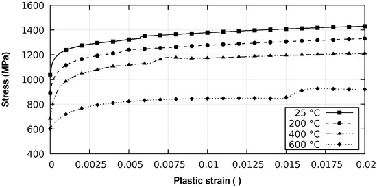
Figure 2.
Hardening curve data of the rolls.
The temperature-non-dependent parameters are density , specific heat and Poisson’s ration The temperature-dependent properties are indicated in Table 2. The reference temperature for the considered thermal expansion is .
Table 2.
Temperature-dependent material properties of the rolls.
2.1.2. Strip
The aluminum strip was treated as an elastic–plastic material with linear isotropic hardening. The thermo-physical data (density, thermal conductivity, specific heat) were implemented according to the A1-6061-T6 alloy, referring to [31]. The latent heat during the solidification of the aluminum was also taken into account. The dependence of the Young modulus of the strip , plastic hardening modulus of the strip (the slope of the stress versus plastic strain curve) and the yield stress of the strip with respect to the temperature are shown in Figure 3. The Poisson’s ration of the strip was considered as . Table 3 indicates the thermal expansion values for different temperatures of the material of the strip with reference temperature .
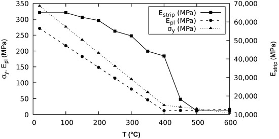
Figure 3.
Elastic–plastic properties of the material of the strip.
Table 3.
Thermal expansion of the material of the strip.
2.1.3. Shaft
The shaft was modeled as an elastic solid with the Young modulus = 210,000 MPa and Poisson’s ratio .
2.2. Boundary Conditions and Interactions
Reference process conditions and parameter variations were defined, with reference to the studies present in the literature, relative to the aluminum alloy strip production [19,21,23,32]. The levels of varied parameters were defined according to the cited studies in order to investigate a reasonably wide range of physical conditions [33].
2.2.1. Initial Conditions
- The initial temperature of the roll and the shaft were considered as equal to the environmental temperature ;
- The initial temperature of the strip was equal to the inlet temperature and varied according to the parameter. The reference values considered were and .
2.2.2. Mechanical Conditions
- The symmetry condition at the middle axes of the strip was defined.
- The shaft rotation speed was imposed according to the tangential velocity of the rolls to achieve. The reference value for the tangential velocity was . Five levels were investigated, as indicated in Table 4;
Table 4. Physical data and casting conditions of the process.
- The interference fit interaction between the roll (inner surface in Figure 1) and the shaft was computed by considering the rough friction model according to the geometry and thermal conditions of the parts during the whole simulation;
- The nodes of the inlet surface were fixed considering the coordinate system for the strip in Figure 1 (). The nodes of the outlet surface were constrained to remain on the same plane, avoiding the longitudinal displacements ().
2.2.3. Thermal Conditions
- The inlet temperature of the liquid metal at the inlet nozzle was the constraint ;
- The heat fluxes due to water-cooling system were computed as follows:where is the specific heat flux at a point on the inner surface of the roll, is the temperature of the point and is the water-cooling reference temperature. The water-cooling heat transfer coefficient varies according to Table 4 with the reference value ;
- The heat fluxes between the outer surface of the roll and the surrounding air were computed as follows:where the reference temperature of the air and the heat transfer coefficient .
2.2.4. Roll–Strip Contact
The roll–strip mechanical contact was defined by assuming the Coulomb friction model with the friction coefficient . The thermal contact was defined by considering a contact conductance coefficient relative to the following heat flux equation:
where is the specific heat flux between points in contact and and are, respectively, the temperature of the roll and strip points in contact. The contact conductance coefficient was varied through five values, as shown in Table 4, and its reference value was .
2.3. Numerical Settings
To perform the simulation the plane strain mesh was defined with the characteristics presented in Table 5. The adaptive mesh was used for the strip in order to define Eulerian boundary conditions. The global and local view of the mesh are represented in Figure 4. In order to reach a reasonable time of execution, a mass-scaling technique was adopted. The value for target time increment for the explicit iteration was calibrated a posteriori to minimize the influence of the mass scaling on the results.
Table 5.
Mesh elements used in the model.
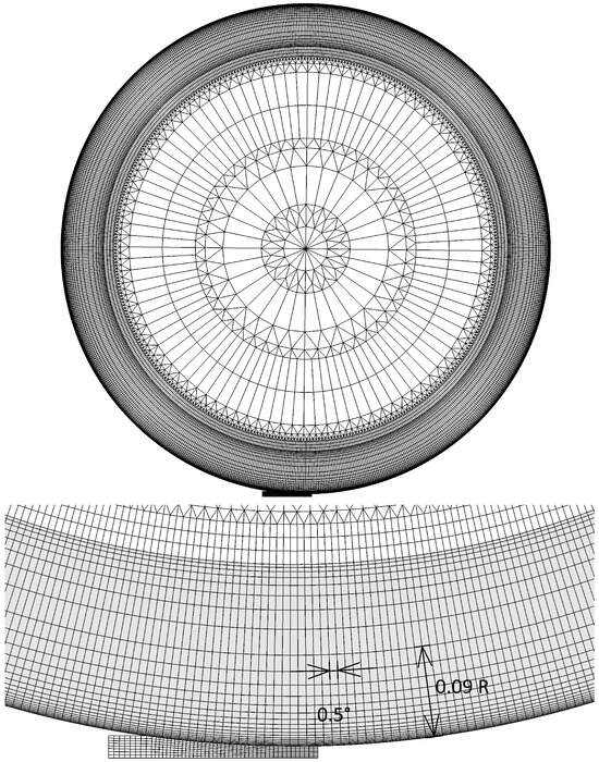
Figure 4.
Global and local view of the mesh of the model (R is the external radius of the roll).
2.4. Fatigue Modeling
To evaluate the thermo-mechanical fatigue damage, the equivalent strain criterion [34] was used. The equivalent strain is assumed as the maximum Von Mises value during the cycle of the amplitude of the deviatoric strain tensor:
The deviatoric strain tensor is computed as follows:
where is the identity tensor. The mean strain tensor is the solution of the following optimization problem:
To compute the equivalent strain, the min–max optimization problem was solved [35] by using a Python optimization script, considering the Basin-hopping and Powell optimization methods.
3. Results
Table 6 summarizes the levels of the parameters investigated and the corresponding level index.
Table 6.
Levels of the process parameters varied in the study.
3.1. Temperature and Stress Fields
Figure 5a shows the temperature field after 8 cycles in the reference process conditions. The maximum temperature at the external surface of the roll reaches and minimum temperature . There is a high temperature gradient at the external surface of the roll near the contact zone. This high temperature gradient is due to the high heat fluxes from the hot strip.
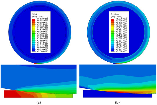
Figure 5.
Global and strip–roll contact zone view: (a) temperature field , (b) Von Mises stress field .
As shown in Figure 5b, the high temperature gradient causes high stresses near the contact area. High temperature and stress gradients are present at the external surface of the roll. Due to the high stresses, the yield condition is reached and the plastic flow is present during the first rotations of the roll.
3.2. Stress Cycle
Figure 6 shows the stress history during the rotation of the roll, considering the radial , tangential , axial and shear stresses. The angular position in Figure 6 corresponds to the last angular position before the point comes in contact with the liquid metal as schematically represented in Figure 1. It is possible to distinguish two main parts during the rotation of the roll: contact zone (the left side of the plot) and free zone (the right side of the plot). Radial and shear stresses, and , are principally determined by the mechanical contact interaction between the strip and the roll. Tangential and axial stresses, and , are mainly influenced by the temperature gradient and the interference fit interaction between the roll and the shaft.
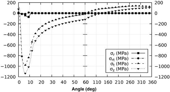
Figure 6.
Radial , tangential , axial and shear stresses during the rotation of the roll.
Figure 6 shows that high compressive stresses arise at the contact zone. At the contact zone, stresses, due to strip–roll mechanical contact interaction ( and ), are lower than the those determined by the temperature gradient and the related thermal expansion ( and ). On the other hand, tensile stresses are present far away from the contact area: and . These stresses are determined by the absence of the high temperature gradient at the surface, residual stresses and the global temperature field. The influence of the roll–shaft interference fit interaction is relatively negligible, with average roll–shaft contact pressure . The global temperature field and the thermal expansion of the roll decrease the effective interference and the contact pressure between the roll and the inner shaft.
The results show that a multiaxial out-of-phase cyclic load is present, which causes the thermo-mechanical fatigue (or the thermal-gradient fatigue) damage.
The stress cycle shows that the stress state is only roughly approximately bi-axial and in-phase with stresses directed along the external surface of the component (tangential and axial). The out-of-plane stress (radial direction) is caused by the mechanical contact, and its value is relatively small compared to the thermal stresses.
3.3. Influence of Process Parameters
3.3.1. Maximum Temperature of the Roll
Figure 7 shows the influence of the process parameters on the maximum temperature at the external surface of the roll .
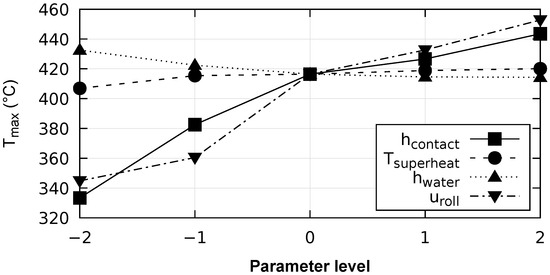
Figure 7.
Maximum temperature on the external surface of the roll, depending on process parameters.
- As the strip–roll contact conductance coefficient rises from to , the maximum temperature increases from to . This effect is caused by the increasing heat fluxes between the strip and the roll at the contact zone;
- As the superheat temperature rises from to , the maximum temperature rises from to . This effect is caused by the higher heat fluxes from the liquid strip to the roll because of the higher strip inlet temperature;
- As the water-cooling heat transfer coefficient rises from to , the maximum temperature decreases from to . The cooling system tends to decrease the global temperature field of the roll;
- As the tangential velocity of the rolls rises from to , the maximum temperature rises from to . The maximum temperature of the roll is mostly influenced by the level of the heat fluxes along the strip–roll contact length. In the considered process conditions for low roll speeds, the surface temperature of the strip decreases more rapidly and the rate of the temperature change of the roll is higher. In these conditions, the heat fluxes’ effect on the point temperature along the strip–roll contact length tends to be lower. Thus, for relatively low roll speeds, the material point tends to reach its maximum temperature earlier with lower values. The opposite behavior occurs for higher roll speeds. The roll speed also influences the average temperature of the component and, in particular, the minimum temperature at the outer surface during the roll rotation. As the roll speed increases, the average temperature tends to increase due to the lower cooling action of the water-cooling system during the roll cycle. It should be pointed out that this last phenomenon has little influence on the actual maximum temperature of the roll, which is more driven by the heat flux distribution along the contact zone.
Considering the levels taken into account, the tangential velocity of the rolls and the strip–roll contact conductance coefficient are the most influential parameters in the evaluated range.
3.3.2. Maximum Contact Pressure
The influence between the maximum contact pressure and the process parameters is shown in Figure 8.
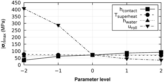
Figure 8.
Maximum contact pressure on the external surface of the roll, depending on process parameters.
- As the strip–roll contact conductance coefficient rises from to , the maximum contact pressure increases from to ;
- As the superheat temperature rises from to , the maximum contact pressure decreases from to ;
- As the water-cooling heat transfer coefficient rises from to , the maximum contact pressure increases from to ;
- As the tangential velocity of the rolls rises from to , the maximum contact pressure decreases from to . The influence of the velocity of the rolls is more relevant for smaller velocities. Due to more rapid solidification process at relatively low speed values, the mechanical contact pressure increases significantly and can contribute to the wear damage of the roll.
The mechanical contact interaction between the strip and the roll is mainly influenced by the solidification process of the strip along the casting direction. In particular, the mechanical contact stresses are influenced by the distance between the inlet surface and the point of the full solidification of the strip. This quantity is defined as sump depth and determines the main portion of the strip subjected to the rolling. As the solid portion of the strip undergoing the rolling increases (lower superheat temperature, lower roll speed, more efficient water-cooling system or more intense thermal contact), the contact pressure tends to increase. Considering the levels taken into account, the tangential velocity is the most influential parameter. The influence of the strip–roll contact conductance coefficient on the mechanical contact interaction is not negligible.
3.3.3. Accumulated Plastic Strain
Figure 9 shows the influence of the process parameters on the accumulated plastic strain after eight cycles of the roll.
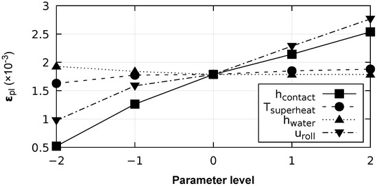
Figure 9.
Accumulated equivalent plastic strain on the external surface of the roll, depending on process parameters.
It should be noted that, for all the simulations, the equivalent plastic strain increment tends to decrease during the eight cycles. In some cases, for example, for high values of the contact heat transfer coefficient, the plastic strain increment is visible only during the first two or even during the first load cycle only. Such a behavior was confirmed by running an additional 19 cycles of simulation for the reference conditions, which showed that, after the first cycles, the elastic shake-down phenomenon occurs. The attainment of the elastic shake-down conditions is even faster if the isotropic hardening of the material occurs.
In the reference conditions, the accumulated plastic strain after eight rotations of the roll . The accumulated plastic strain is related to the fatigue damage and, this is caused by the cyclic thermo-mechanical load followed by the plastic flow.
- An increase in the strip–roll contact conductance coefficient from the value of to causes a monotonous increase in the accumulated plastic strain from to . This is caused by the increasing contact heat fluxes between the strip and roll, determined by the contact conductance coefficient. Higher temperature gradients and thermal strains cause the stress to rise and the subsequent plastic flow;
- The influence of the melt superheat temperature is relatively small. As the melt superheat temperature rises from to , the accumulated plastic strain increases from to . These results are due to the higher thermal shock that occurs when the liquid aluminum touches the external surface of the cooled roll;
- As the tangential velocity of the rolls rises from to , the accumulated plastic strain increases from to .
The results show that the strip–roll contact conductance coefficient and the tangential velocity of the rolls from are the most influential parameters in the plastic flow phenomenon. These two parameters contribute to the higher temperature gradient at the roll surface and the thermal softening of the material, causing damaging plastic flow.
3.3.4. Equivalent Strain
Figure 10 shows the relationship between the thermo-mechanical fatigue load, represented by the equivalent strain , and the process parameters. In the reference conditions, the equivalent strain . The results show that the most relevant parameter to consider to evaluate the fatigue damage is the contact conductance coefficient .
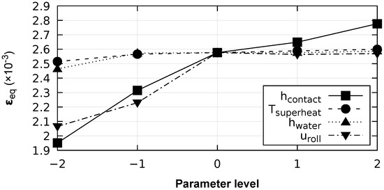
Figure 10.
Equivalent strain value for the fatigue evaluation, depending on process parameters.
- In fact, as the strip–roll contact conductance coefficient rises from to the equivalent strain increases monotonously from to . This result shows the importance of the contact heat fluxes between the strip and the roll in the thermo-mechanical fatigue damage. Due to a higher contact conductance, contact heat fluxes increase and so does the temperature gradient at the external surface of the roll;
- As the melt superheat temperature rises from to , the equivalent strain slightly increases from to ;
- As the water-cooling heat transfer coefficient varies between and , the equivalent strain remains almost constant, with a variation from to ;
- The influence of the tangential velocity of the rolls on the equivalent strain is more relevant for small values of the roll speed. As the tangential velocity of the rolls rises from to , the equivalent strain increases from to . For higher values of the velocity, the equivalent strain remains almost constant. This behavior could suggest the influence of the contact pressure on the equivalent strain value for small velocities of the rolls. In fact, the contact pressure increases significantly for very low roll speeds, as shown in Figure 8, and influences the stress tensor state.
4. Conclusions
A two-dimensional coupled thermo-mechanical numerical model was defined. An explicit integration method and mixed Lagrangian-Eulerian analysis was performed, simulating eight rotations of the roll. The temperature-dependent properties were used and the latent heat of the aluminum was taken into account. The plastic behavior of the material of the roll was considered, and the kinematic cycling hardening model was defined based on the tensile test experimental data. The liquid aluminum initial temperature and the strip roll thermo-mechanical contact were defined with a contact conductance coefficient and the Coulomb friction model. The interference fit between the roll and the shaft was considered as well.
The results showed that a cyclic out-of-phase thermo-mechanical fatigue phenomenon occurs. Thermal stresses are considerably higher than those caused by the roll–strip mechanical contact.
Table 7 summarizes the results obtained and represents how a process parameter influences a damage parameter in the considered range. The results showed that, in the considered range, the most influential parameters are the heat contact conductance coefficient , which dominates the thermo-mechanical load, and the tangential velocity of the rolls , which influences the thermal field and mechanical contact interaction between the roll and the strip. In fact, the results showed that, at a relatively low production rate, the contact pressure increases () and can aggravate the wear damage of the roll.
Table 7.
Influence of the process parameters on the thermo-mechanical fatigue damage: relatively strong positive correlation, very small positive correlation, 0 relatively negligible influence, very small negative correlation, relatively strong negative correlation.
The obtained data could be used to make choices to minimize the damaging conditions of the roll and to reduce the thermo-mechanical fatigue phenomenon. On the other hand, the results could suggest which variables are more critical to design an experimental evaluation of the roll stress conditions and the prediction of their lifespans.
Author Contributions
Conceptualization, R.S.; methodology, R.S.; software, R.S.; validation, R.S. and A.M.; formal analysis, R.S.; investigation, R.S.; data curation, R.S.; visualization, R.S., N.Z. and A.M.; writing—original draft preparation, R.S.; writing—review and editing, R.S., N.Z. and A.M.; supervision, A.M.; project administration, A.M. All authors have read and agreed to the published version of the manuscript.
Funding
This research received no external funding.
Data Availability Statement
Data are available upon request from the authors.
Acknowledgments
The provision of information on the process conditions and material data by the Lucchini RS SpA and, in particular, by Ing. Andrea Ghidini is gratefully acknowledged.
Conflicts of Interest
The authors declare no conflicts of interest.
References
- Bessemer, H. Improvement in the Manufacture of Iron and Steel. U.S. Patent N. 49053, 25 July 1865. [Google Scholar]
- Maleki, A.; Taherizadeh, A.; Hoseini, N. Twin Roll Casting of Steels: An Overview. ISIJ Int. 2017, 57, 1–14. [Google Scholar] [CrossRef]
- Akiyoshi, R.; Hori, M.; Matsui, K.; Hirata, A.; Fujita, K.; Ogawa, S. Roll Cooling Structure for Twin Roll Continuous Caster. U.S. Patent N. 5887644, 30 March 1999. [Google Scholar]
- Zapuskalov, N. Twin Roll Comparison of Continuous Strip Casting with Conventional Technology. ISIJ Int. 2003, 43, 1115–1127. [Google Scholar] [CrossRef]
- Ding, P.; Pan, F.; Jiang, B.; Wang, J.; Li, H.; Wu, J.; Xu, Y.; Wen, Y. Twin-roll strip casting of magnesium alloys in China. Trans. Nonferrous Met. Soc. China 2008, 18, 1003–6326. [Google Scholar] [CrossRef]
- Haga, T.; Ikawa, M.; Watari, H.; Kumai, S. High speed twin roll casting of 6016 strip. J. Achiev. Mater. Manuf. Eng. 2006, 18, 371–374. [Google Scholar]
- Zhao, H.; Li, P.; He, L. Microstructure and mechanical properties of an asymmetric twin-roll cast AZ31 magnesium alloy strip. J. Mater. Process. Technol. 2012, 212, 1670–1675. [Google Scholar] [CrossRef]
- Sakaguchi, H.; Haga, T.; Watari, H.; Kumai, S. High speed twin roll casting of 6016 aluminium alloy strip. J. Achiev. Mater. Manuf. Eng. 2007, 20, 495–498. [Google Scholar]
- Haga, T.; Suzuki, S. A high speed twin roll caster for aluminum alloy strip. J. Mater. Process. Technol. 2001, 113, 291–295. [Google Scholar] [CrossRef]
- Gras, C.; Meredith, M.; Hunt, J.D. Microdefects formation during the twin-roll casting of Al–Mg–Mn aluminium alloys. J. Mater. Process. Technol. 2005, 167, 62–72. [Google Scholar] [CrossRef]
- Chen, S.; Chen, J.; Yu, J.; Lv, L. Simulation of Microstructures in Solidification of Aluminum Twin-roll Casting. J. Manuf. Process. 2012, 22, 1452–1456. [Google Scholar] [CrossRef]
- Hadadzadeh, A.; Wells, M.A. Inverse and centreline segregation formation in twin roll cast AZ31 magnesium alloy. Mater. Sci. Technol. 2015, 31, 1715–1726. [Google Scholar] [CrossRef]
- Neuser, M.; Schaper, M.; Grydin, O. Mechanical and Microstructure Characterisation of the Hypoeutectic Cast Aluminium Alloy AlSi10Mg Manufactured by the Twin-Roll Casting Process. J. Manuf. Mater. Process. 2023, 7, 132. [Google Scholar] [CrossRef]
- Guthrie, R.; Tavares, R. Mathematical and physical modelling of steel flow and solidification in twin-roll/horizontal belt thin-strip casting machines. Mater. Sci. Technol. 1998, 22, 851–872. [Google Scholar] [CrossRef]
- Wang, D.; Zhou, C. A top side-pouring twin-roll caster for metals strips. J. Mater. Process. Technol. 2014, 214, 916–924. [Google Scholar] [CrossRef]
- Lee, Y.S.; Kim, H.W.; Cho, J.H. Process parameters and roll separation force in horizontal twin roll casting of aluminum alloys. J. Mater. Process. Technol. 2015, 218, 48–56. [Google Scholar] [CrossRef]
- Kim, M.-S.; Kim, H.-W.; Kim, S.-H.; Kumai, S. Role of Roll Separating Force in High-Speed Twin-Roll Casting of Aluminum Alloys. Metals 2019, 9, 645. [Google Scholar] [CrossRef]
- Zeng, J.; Koitzsch, R.; Pfeifer, H.; Friedrich, B. Numerical simulation of the twin-roll casting process of magnesium alloy strip. J. Mater. Process. Technol. 2009, 209, 2321–2328. [Google Scholar] [CrossRef]
- Saxena, A.; Sahai, Y. Modeling of Fluid Flow and Heat Transfer in Twin-Roll Casting of Aluminum Alloys. Mater. Trans. 2002, 43, 206–213. [Google Scholar] [CrossRef]
- Hadadzadeh, A.; Wells, M.A. Mathematical modeling of thermo-mechanical behavior of strip during twin roll casting of an AZ31 magnesium alloy. J. Magnes. Alloy 2013, 43, 101–114. [Google Scholar] [CrossRef]
- Lee, Y.S.; Kim, H.W.; Cho, J.H. Effect of Casting Parameters on Roll Separation Force during Twin Roll Casting. Procedia Eng. 2014, 81, 1547–1552. [Google Scholar] [CrossRef]
- Toyoshima, S.; Takahashi, Y. A Numerical Simulation of Forming Processes for Semi-solid Materials. ISIJ Int. 1991, 31, 577–582. [Google Scholar] [CrossRef][Green Version]
- Lee, Y.S.; Kim, H.W.; Cho, J.; Chun, S.H. Coupled thermal-fluid-mechanics analysis of twin roll casting of A7075 aluminum alloy. Met. Mater. Int. 2017, 23, 923–929. [Google Scholar] [CrossRef]
- Rodrigues, C.M.G.; Ludwig, A.; Wu, M.; Kharicha, A.; Vakhrushev, A. Two-phase viscoplastic model for the simulation of twin roll casting. J. Mater. Process. Technol. 2020, 286, 116814. [Google Scholar] [CrossRef]
- Zapuskalov, N.; Vereschagin, M. Wear of Roll Surface in Twin-roll Casting of 4.5% Si Steel Strip. ISIJ Int. 2000, 40, 589–596. [Google Scholar] [CrossRef]
- Saxena, A.; Sahai, Y. Modeling of Thermo-Mechanical Stresses in Twin-Roll Casting of Aluminum Alloys. Mater. Trans. 2002, 43, 214–221. [Google Scholar] [CrossRef]
- Dündar, M.; Beyhan, B.; Birbaşar, O.; Altuner, H.M.; Işıksaçan, C. Surface Crack Characterization of Twin Roll Caster Shells and Its Influence on As-Cast Strip Surface Quality. In Light Metals 2013; Sadler, B.A., Ed.; The Minerals, Metals & Materials Series; Springer: Cham, Switzerland, 2013. [Google Scholar]
- Wang, M.; Gu, T.; Yang, N.; Ma, Q. Study on microstructure and fatigue crack propagation of roll sleeves in an aluminum strip casting machine. Eng. Fail. Anal. 2013, 31, 338–343. [Google Scholar] [CrossRef]
- ©Dassault Systèmes. Abaqus/CAE. User’s Guide; Dassault Systèmes Simulia Corp.: Providence, RI, USA, 2014. [Google Scholar]
- De Souza Neto, E.A.; Perić, D.; Owen, D.R.J. Computational Methods for Plasticity: Theory and Applications; John Wiley & Sons, Ltd.: Chichester, UK, 2008; p. 188. [Google Scholar]
- Kenneth, C.M. Recommended Values of Thermophysical Properties for Selected Commercial Alloys; Woodhead Publishing Limited: Cambridge, UK, 2002; pp. 64–67. [Google Scholar]
- Bondarenko, S.; Stolbchenko, M.; Schaper, M.; Grydin, O. Numerical Analysis of Twin-Roll Casting of Strips with Profiled Cross-Section. Mater. Res.-Ibero-Am. J. 2018, 21, e20171098. [Google Scholar] [CrossRef]
- Li, B.Q. Producing thin strips by twin-roll casting—part II: Process modeling and development. JOM 1995, 47, 13–17. [Google Scholar]
- Ciavarella, M.; Monno, F. A comparison of multiaxial fatigue criteria as applied to rolling contact fatigue. Tribol. Int. 2010, 43, 2139–2144. [Google Scholar] [CrossRef]
- Bernasconi, A. Efficient algorithms for calculation of shear stress amplitude and amplitude of the second invariant of the stress deviator in fatigue criteria applications. Int. J. Fatigue 2002, 24, 649–657. [Google Scholar] [CrossRef]
Disclaimer/Publisher’s Note: The statements, opinions and data contained in all publications are solely those of the individual author(s) and contributor(s) and not of MDPI and/or the editor(s). MDPI and/or the editor(s) disclaim responsibility for any injury to people or property resulting from any ideas, methods, instructions or products referred to in the content. |
© 2024 by the authors. Licensee MDPI, Basel, Switzerland. This article is an open access article distributed under the terms and conditions of the Creative Commons Attribution (CC BY) license (https://creativecommons.org/licenses/by/4.0/).