Abstract
Unmanned aerial vehicle (UAV) remote sensing has found extensive applications in various fields due to its ability to quickly provide remote sensing imagery, and the rapid, even automated, geometric registration of these images is an important component of their time efficiency. While current geometric registration methods based on image matching are well developed, there is still room for improvement in terms of time efficiency due to the presence of the following factors: (1) difficulty in accessing historical reference images and (2) inconsistencies in data sources, scales, and orientations between UAV imagery and reference images, which leads to unreliable matching. To further improve the time efficiency of UAV remote sensing, this study proposes a fully automatic geometric registration framework. The workflow features the following aspects: (1) automatic reference image acquisition by using online map services; (2) automatic ground range and resolution estimation using positional and orientation system (POS) data; (3) automatic orientation alignment using POS data. Experimental validation demonstrates that the proposed framework is able to carry out the fully automatic geometric registration of UAV imagery, thus improving the time efficiency of UAV remote sensing.
1. Introduction
Remote sensing technology has experienced rapid development in recent years, which is capable of providing useful imagery [] for areas such as environmental monitoring [,,] and emergency response [,]. Among all platforms, UAV-based remote sensing, due to its low cost, ease of operation, and wide field of view, is being used in almost every application that needs Earth observation imagery [,].
Before being used, UAV images need to undergo a geometric registration process to remove the geometric distortion introduced by the various positions and orientations of the camera []. For this purpose, traditional photogrammetry techniques such as direct georeferencing (DG) [] and aerial triangulation (AT) [] can be adopted, which may be performed without using any reference images (except for the digital elevation model (DEM) needed by DG). However, the geometric accuracy of DG may not be good enough for high-accuracy applications, and AT is too complex for simple applications.
Another way to carry out the geometric registration of UAV imagery is using image matching techniques, which does not require too much photogrammetric background knowledge, and geometric registration based on image matching is often an accuracy insurance [,]. The core idea is to register a sensed UAV image to a reference image, the basic steps of which include the following: reference image preparation, geometric preprocessing, conjugate points extraction through an image matching technique, transformation model construction, and resampling []. It is worth mentioning that automated geometric registration is made possible mainly by the advent of image matching technology, which is one of the reasons why image matching techniques are currently being paid more and more attention.
However, the aforementioned studies failed to address some issues that are also important for applications, such as how to obtain reference images and, once obtained, how to locate the regions to be matched from larger or even global-wide images. In addition, the significant scale and rotation differences between UAV imagery and reference images may make feature matching fail and thus should also be addressed.
This paper proposes a fully automatic geometric registration framework for UAV imagery based on online map services and a POS to address the aforementioned issues. First of all, POS data are used for the automated estimation of the ground range and resolution of the sensed UAV imagery. Secondly, the estimated ground range and resolution are used to calculate the suitable range and zoom level of the online map service to be used as reference images. Then, clips from the online map service are used as reference images, which are very important for applications since traditional reference images are not widely accessible to the public. In addition, POS data are also used for orientation alignment between the sensed UAV imagery and the reference images, since orientation misalignment may pose challenges to the feature matching process. Feature matching is then carried out to extract conjugate points from the sensed UAV imagery and the reference images, which are then used for the geometric registration of the sensed UAV imagery.
In summary, the main contribution of this paper is a fully automated geometric registration framework of UAV imagery, including the following:
- (1)
- An automated ground range and resolution estimation method of the sensed UAV imagery using the corresponding POS data;
- (2)
- An automated reference image acquisition method using online map services as the source of reference images and the automated estimation of the range/zoom level needed;
- (3)
- Automated orientation misalignment between the sensed images and the reference images using the orientation provided by the POS.
The paper is organized as follows: Section 2 introduces related works on the automatic geometric registration methods of UAV imagery; Section 3 explains in detail how to carry out automatic ground range and resolution estimation, automatic reference image acquisition, and geometric registration; experimental verification of the proposed framework is presented in Section 4, followed by a discussion section in Section 5 and a brief conclusion in Section 6.
2. Related Works
This section provides a brief overview of related research on the automated geometric registration of UAV remote sensing imagery. There are many related works on the topic, some of which can be used for geometric registration without using a reference image, such as DG [] and AT [,,,]. However, the accuracy of the former method is not good enough for geometric registration, and the latter method is too complex for a non-professional application, so they are not covered in this paper. Geometric registration based on image matching is easier to carry out and is covered by this paper.
2.1. Automated Reference Image Acquisition
For most of the research, the workflow starts from a well-prepared image pair, which means that the reference image is already an input and shares roughly the same ground range with the sensed UAV image, such as in [,,]; even some studies that claim to be automated still require the input of an input reference image []. In fact, reference image acquisition is very import for real applications but has mostly been ignored, since not all studies have access to suitable data sources, not to mention that geometric registration is to be carried out by people from other fields or even some members of the general public.
A database of reference images can be used as the input [,], where the actual reference image is automated and selected by the footprint calculated from the metadata of the sensed image. However, such databases are also a big challenge for most applications or users.
Rasterized online map services such as OpenStreetMap have already been included in the database in [], but it is still offline and not fully automated. There are also cases [] where the reference image is used online without manual interference and the range and zoom level of the online map service is automatically calculated. However, the selection of the ground control points (GCPs) is manually performed, making it not fully automated.
2.2. Geometric Preprocess
A geometric preprocess is normally adopted before image matching since an obvious geometric distortion or orientation misalignment between the reference image and the sensed UAV imagery usually exists. Based on whether the reference image or the sensed image is geometrically preprocessed, the preprocessing procedure can be classified as forward methods and backward methods.
- (1)
- Forward methods. The sensed images are preprocessed to remove the geometric distortion between the sensed image and the reference image. Geometric preprocessing such as rough orthorectification can be carried out on the sensed image before feature matching using positioning and orientation data [] or navigation data []. Even complicated methods like AT can be adopted [] in geometric preprocessing.
- (2)
- Backward methods. The reference images are preprocessed to remove their geometric distortion compared to the sensed images. A sensed image can be simulated from a reference image [] before feature matching; this may be better for highly obliquely sensed images since if the forward methods are adopted, the quality of the orthorectified image will not be ideal for matching.
2.3. Image Matching
Image matching is the most important technique that makes automated geometric registration possible. Image matching methods can be categorized into intensity-based registration (including an area-based method, optical flow estimation), feature-based registration (including a conventional feature-based method, novel feature-based registration by deep learning), and registration based on a combination method [].
Intensity-based methods, including area-based methods (such as mutual information [], cross correlation [], phase congruency [], and optical flow [] algorithms), utilize intensity information like gradients to carry out geometric registration. In the meantime, feature-based registration methods using objects called “features” composed from the pixels of an image are used to measure the similarity between different images. These features can be hand-crafted point features (such as Moravec, Harris, SIFT [], and FAST) or line/region features or features extracted by neural networks (such as GNN [,], SuperPoint [], and others [,,,]). These image match techniques have their own advantages in different aspects and have been used in many applications.
3. Methods
A brief overview of the proposed framework is firstly presented in this section. Then, ground range and resolution estimation, reference image acquisition, and geometric registration is explained in detail in the following part.
3.1. Overview
The flowchart of the proposed framework is illustrated in Figure 1.
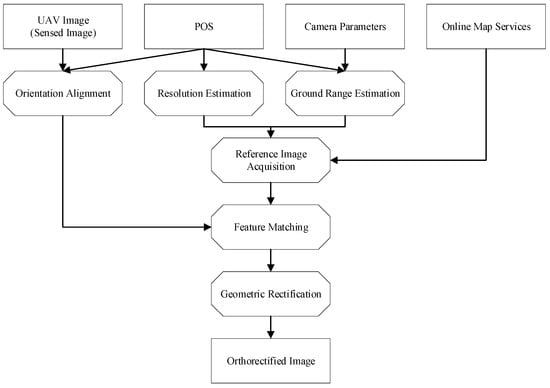
Figure 1.
Flowchart of the proposed framework.
- (1)
- Ground range estimation and resolution estimation. The proposed framework first carries out ground range and resolution estimation using the same principle as DG based on POS data and camera parameters.
- (2)
- Reference image acquisition. The zoom level and tile IDs of the corresponding online map service can be derived using the estimated ground range and resolution based on the tiling scheme of the online map service. After that, tiles from the online map service are obtained to form a reference image using the derived zoom level and tile ID.
- (3)
- Orientation alignment. The sensed image undergoes rotation based on the heading angle in the POS data to align its orientation roughly with that of the reference image.
- (4)
- Feature matching. The rotated sensed image is matched with the reference image to extract conjugate points for the image pair.
- (5)
- Geometric rectification. Finally, a transformation model is fitted using the conjugate points, which is then is used to carry out the geometric rectification of the sensed image by resampling.
3.2. Ground Range and Resolution Estimation
Ground range and resolution need to be estimated for the preparation of a reference image, which are estimated mainly using the POS in the proposed framework. The ground range is estimated using the collinearity equation, (the same equation used by DG), and the ground resolution is estimated using the geometric relationships during the exposure.
3.2.1. Ground Range Estimation
The automated estimation of ground range is achieved through the utilization of UAV POS information, camera parameters, and the DEM. The process involves establishing collinearity equations and employing direct georeferencing methods to obtain the geographic coordinates corresponding to the four corner points.
Figure 2 shows the geometric relationship between a ground point and its image , which is described by collinearity equations as follows:
where and are the image plane coordinates in the UAV imagery that can be derived from the pixel coordinates using camera parameters, is the camera’s focal length, , , and are the object space coordinates of the camera station, , , and are the object space coordinates of the object point (where the elevation can be obtained from the DEM), and , , and ( = 1,2,3) are the components of the rotation matrix derived from the image orientation ( in the figure). Depending on the selected object coordinate system, the rotation matrix can be obtained from the POS data using the rotation matrix method.
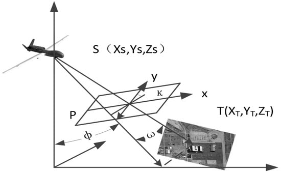
Figure 2.
Geometric relationship between a ground point, T, and its image.
Another form of the collinearity equations are as follows, which can be used to deduce the object space coordinates from image space coordinates with the DEM through an iterative process.
The ground range of the reference image (the longitude and latitude of corner point are and , ) to be obtained corresponds to the bounding rectangle of the quadrilateral formed by these four corner points, as illustrated by the dashed lines in Figure 3.
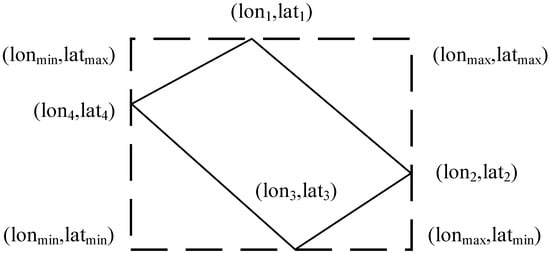
Figure 3.
Automatically estimated range of the sensed image.
The maximum longitude , minimum longitude , maximum latitude , and minimum latitude are derived from the ground range as follows:
3.2.2. Estimation of Ground Resolution
The geometric relationships during the exposure of the sensed image are shown in Figure 4:
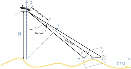
Figure 4.
Geometric relationships during the exposure.
The formula for calculating the ground sampling distance (GSD) is as follows:
is the ground resolution along the direction of photography, is the resolution perpendicular to the direction of photography, is the relative height between the camera center and the ground point, is the camera focal length, and represents the tilt angle of the image (the angle between the principal axis and the plumb line). is the physical size of a pixel. can be obtained by subtracting the ground point’s elevation from the projection center’s elevation, and the ground point’s elevation can be obtained by reading the DEM.
3.3. Reference Image Acquisition
Automatic reference image acquisition is performed by using an online map service as the image provider. The organization of online map services and the transformation between geographic coordinates and tile IDs are introduced in the following parts.
3.3.1. Organization of Online Map Services
The core idea of online image services includes the following: (1) constructing an image pyramid with certain zoom levels to store global imagery of different scales; (2) dividing the global imagery within each zoom level into uniformly sized tiles and numbering them according to predefined gridding rules; (3) sending the corresponding tiles to the requester based on the requested spatial extent and zoom level.
Taking the TMS (tile map service) as an example, its data organization follows a structure similar to a spatial quadtree, as illustrated in Figure 5.
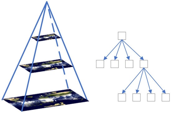
Figure 5.
Tile organization of TMS.
The global image in zoom level 0 of the pyramid is divided into one tile as is shown in Figure 6, in zoom level 1 it is divided into two rows and two columns, a total of four tiles, and so on. Additionally, different tiles within each level are numbered and stored based on their row and column numbers. Therefore, each tile can be uniquely identified by its column number (X), its row number (Y), and the zoom level (Z) in which it resides.
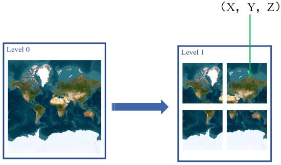
Figure 6.
Global imagery hierarchy diagram.
3.3.2. Coordinates Transformation
For online map services, accessing tiles for a specified area requires the row and column numbers of the tile as well as the zoom level. Once these parameters are determined, tiles can be obtained by constructing a URL with specific rules. Therefore, the key to obtaining imagery for a specified range from online image services is to determine the XYZ parameters for each tile.
The first step is to determine the zoom level, which has a well-defined relationship with the GSD. This relationship is defined as follows:
where represents the maximum length of the online image and represents the zoom level. From the above formula, it can be observed that with each increase in zoom level of 1, the GSD is halved. This formula can be used to calculate the current resolution of the online image. Similarly, based on the resolution of the sensed image, the zoom level of the online image can be calculated as follows:
It is important to note that the formula for zoom levels may vary depending on the standard used. After confirming the zoom level, the row and column numbers can be calculated based on the geographic coordinates of the ground range:
where is the column index of the tile, is the row index of the tile, and correspond to longitude and latitude, respectively, and is the zoom level .
The reference image can then be automatically obtained by requesting and concatenating all the tiles covered by the ground range.
3.4. Geometric Registration Scheme
With the obtained reference image, geometric registration can then be carried out. The sensed image first undergoes orientation alignment using the POS. Then, feature points are extracted using the SuperPoint network from both the reference image and sensed image and then are matched using the SuperGlue network. The matching results are later used for geometric rectification. The flowchart of geometric registration is shown in Figure 7.
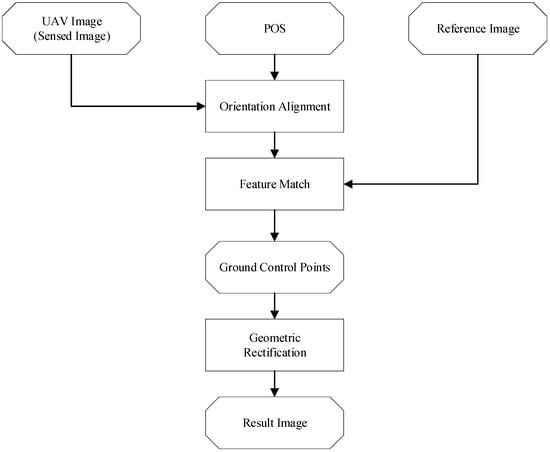
Figure 7.
Geometric registration flowchart.
3.4.1. Orientation Alignment
Currently, there are numerous feature matching methods available for matching UAV imagery with satellite imagery. However, the matching process may still be influenced by orientation misalignment between the reference image and the sensed image. The POS records the orientations of the UAV image at the moment of exposure, allowing for orientation alignment with the reference image.
Orientation alignment can be achieved using direct georeferencing (DG), which considers the effects of the heading angle, pitch angle, and terrain on the imaging process. However, DG requires multiple iterations and DEM readings, resulting in a low computational efficiency. In addition, the precise correspondence between the geometrically corrected and original imagery cannot be accurately described by mathematical relationships due to the iteration process of DG, leading to a reduced matching accuracy.
In fact, rotation or perspective transformation can also be used for orientation alignment with fewer computation costs and a high-accuracy bijective correspondence. The study [] points out that, for the SuperPoint + SuperGlue matching scheme, the heading angle has a significant impact on the matching process, while the pitch angle has a minimal effect. Therefore, the orientation alignment in this study only involves an orientation alignment operation based on the heading angle for the UAV image.
Since the purpose is to find out the correspondence between the pixels in the original sensed image and the reference image while a rotated sensed image is actually being matched to the reference image, the relationship between the original coordinate and the rotated coordinate needs to be determined.
Two-dimensional image rotation refers to rotating a two-dimensional image around a certain center point by a certain angle. The following steps are usually used to achieve the rotation of a two-dimensional image.
Firstly, determine the rotation center. Choose a point in the image as the center of rotation, which can be the center of the image or any other point. Figure 8 shows the case when the origin is chosen as the rotation center.
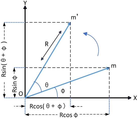
Figure 8.
Two-dimensional image rotation around the origin.
As shown in Figure 8, point is rotated around the origin by an angle, , to obtain point . is the distance from point to the origin, and is the angle between point and the axis. Assuming that the coordinates of are and those of are ), then we have the following:
Rotating around the origin is the most basic case of two-dimensional image rotation. For the general case (rotation around an arbitrary point), the steps are as follows:
- (1)
- Move the rotation point to the origin.
- (2)
- Perform the rotation around the origin.
- (3)
- Translate the rotation point back to its original position.
Then, the relationship between the original coordinate and the rotated coordinate is described by the following formula:
where the translation values are and the rotation angle is . Assuming that the coordinates of the rotation center are , then the formula for calculating the coordinates after rotation is as follows:
Similarly,
3.4.2. Feature Match
One of the key features for matching between drone images and reference images is salient features. During the image matching process, emphasis should be placed on structural features with significant variations between images, such as corners, edges, and gradients. SuperPoint [] and SuperGlue [] are neural network models used for feature detection and matching. They provide efficient and accurate feature detection and matching capabilities, suitable for tasks in computer vision such as keypoint matching and SLAM (simultaneous localization and mapping). They are used as the feature matching scheme in the paper.
SuperPoint is a convolutional neural network used for detecting keypoints in images. It typically consists of convolutional layers, ReLU activation functions, and non-maximum suppression (NMS) layers. During training, SuperPoint learns how to detect keypoints from images through supervised learning, and it generates dense feature descriptors during the testing phase. During detection, SuperPoint performs forward propagation on the image to output the positions and descriptors of the keypoints. The positions of the keypoints are usually represented by pixel coordinates, while the descriptor is a vector used to describe the local features around the keypoints. Its characteristics include efficiency, as it can quickly detect a large number of keypoints in images with high accuracy through SuperPoint.
SuperGlue is a deep neural network composed of multiple convolutional layers and fully connected layers. It is used to learn the matching relationship between keypoints directly and can also perform matching between two sets of keypoints in images. During the matching process, SuperGlue takes the keypoints and descriptors generated by SuperPoint as input and output matching scores and reliability scores for each pair of keypoints. This step effectively filters out inaccurate matches, improving the accuracy of the matching process. As SuperGlue follows an end-to-end training approach, it can directly learn the matching relationship between the keypoints from the data without the need for manually designing feature matching algorithms.
Combining SuperPoint and SuperGlue forms a powerful and efficient system for feature detection and matching. This system can provide efficient and accurate feature matching functionality in practical applications.
3.4.3. Geometric Rectification
Using the list of extracted conjugate points, it is possible to obtain the geographic coordinates of any pixel in the drone image through interpolation. Based on this, the geometric rectification of the drone image can be achieved. The 3rd-order polynomial transformation model is represented as follows:
In the equation above, represents the pixel coordinates measured in the sensed image, denotes the corresponding geographic coordinates, and (i, j = 1, 2, 3…) are the parameters of the polynomial transformation, which can be solved by using the feature match results.
Note that the transformation model is not limited to 3rd-order polynomial transformation; models like 2nd-order polynomial transformation and homographic transformation are also available and follow a similar process.
With the transformation model, differential rectification can be applied to obtain the orthorectified image. The steps of the differential rectification used in this paper include the following:
- (1)
- Calculate the geometric coordinates of the four corners of the warp image (the image to be rectified, which is the sensed image in this context) using the transformation model.
- (2)
- Determine the bounding box and create an empty image using the bounding box;
- (3)
- Choose one pixel in the result image.
- (4)
- Determine the image coordinates of the corresponding original pixel using the transformation model.
- (5)
- Determine the pixel value of the pixel using the local region by interpolation methods such as the nearest neighbor or bilinear interpolation; if the pixel (c, r) is outside the original image, make empty.
- (6)
- Let the gray value of the pixel be .
- (7)
- Repeat steps (3)~(6) until all pixels in the result image are determined.
4. Results
To validate the proposed framework, a data set was collected using a UAV and an EO-IR pod. To show the influence of heading angles, images of the same ground area from all directions were captured. Another purpose of the design of the flight was to ensure that all images were covering the same scene so that the reference image was also the same and that the possible influence of scene difference on the matching process could be avoided. However, since some of the exposure stations were blurred by clouds or mist, some of the images were excluded from the test data set.
The software used for the experiment was developed independently using C++ based on some open-source third-party libraries: (1) GDAL was used in the software to read and write all images; (2) OpenCV was used for basic data structures; and (3) ONNX Runtime was used for the C++ implementation of SuperPoint and SuperGlue.
4.1. Data
The data used in this paper were captured in Guizhou, southwest China, in June 2021. An EO-IR Gimbal Camera onboard a fixed-wing UAV was used to capture optical imagery as well as POS data simultaneously.
During the flight, the UAV platform flew at a relative height of 6000 m (orthometric altitude) and kept 15,000 m distance from the ground mark (as is shown in Figure 9) that it was tracking so that images could be captured from different viewpoints.
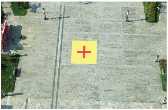
Figure 9.
A picture of the ground mark.
However, due to the existence of clouds, parts of the images were not able to capture the ground mark and were abandoned for the experiment. Figure 10 shows the distribution of all the exposure stations used in this paper, and the picture located in the center of the figure is the ground area where the ground mark was located. Four highlighted stations in the figure were chosen as representatives of images captured from different directions: (a) for heading east, (b) for heading south, (c) for heading west, and (d) for heading north.
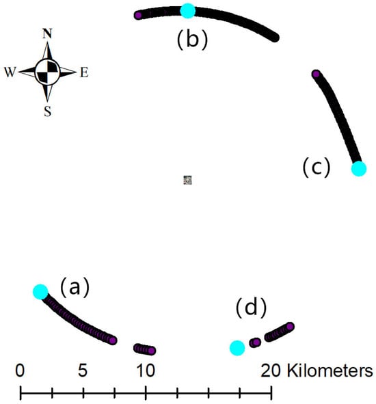
Figure 10.
Distributions of exposure stations.
4.2. Reference Image Acquisition
World imagery provided by the ESRI (Environmental Systems Research Institute) was used in this paper. World imagery provides one-meter or better satellite and aerial imagery for most of the world’s landmass and lower-resolution satellite imagery worldwide []. The highest resolution of the map service around the experimental location is about 0.6 m according to the metadata provided, and the source image was captured on 15 January 2021 and provided by Maxar (Vivid).
4.2.1. Ground Range Estimation Result
The ground range and resolution were estimated using the corresponding POS data and camera parameters and then the reference image clip was acquired. Some of the results are shown in Figure 11 to show the discrepancies of the estimated ground ranges.
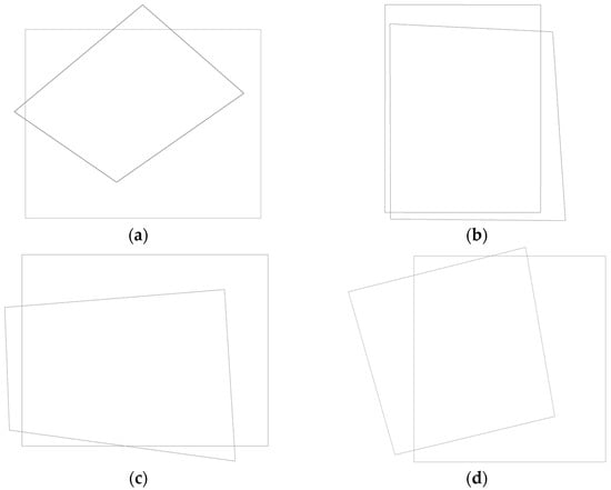
Figure 11.
Comparisons between the estimated ground ranges (the rectangles in the four groups) and the actual ground range covered by the images (the trapeziform in the four groups) from different directions. The corresponding heading angles (in degrees) were as follows: (a) 51, heading northeast; (b) 180, heading south; (c) 266, heading east; and (d) 345, heading northwest.
The accuracy of the estimated ground range was also investigated by comparing the real coordinates of the ground mark with its estimated coordinates. The results show an average error of 50 m; see Figure 12.

Figure 12.
Estimation discrepancies of the ground mark.
Since the ground range was more than 500 m in both the longitude and latitude directions, the ground range estimation error was about 10%, which was good enough for acquiring reference images automatically.
In addition, it was possible for the estimation accuracy to be improved through at least two ways: (1) a better POS could be adopted to give better position and orientation information for the camera; and (2) calibration measures could be taken to improve the accuracy of the POS, since there were misalignments between the camera axis and the axis of the POS.
4.2.2. Resolution Estimation
The estimated GSD of the sensed images was about 0.45 m, and the estimated zoom level was 17. According to the metadata, the resolution of the level 18 image was about 0.6 m and was a suitable zoom level for the sensed image.
4.2.3. Reference Image Automatic Acquisition Result
The automatically obtained image, along with the sensed images, are shown in Figure 13.
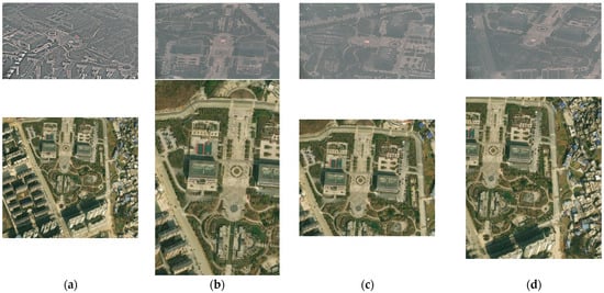
Figure 13.
Sensed images (first row) and obtained reference images (second row). The heading angles(in degrees) of the sensed images are: (a) 51, heading northeast; (b) 180, heading south; (c) 266, heading east; and (d) 345, heading northwest.
As can be seen from Figure 13, all four automatically obtained reference images cover the ground area captured by the four sensed UAV images. Although there are discrepancies in different directions, the main part of the ground area is always covered in the obtained reference images, making them valid reference images to use.
In conclusion, the proposed framework was able to carry out ground range and resolution estimation automatically, as well as obtain the reference images automatically.
4.3. Geometric Registration
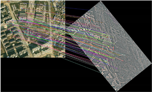
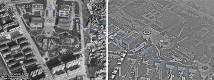
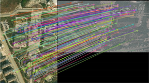
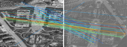
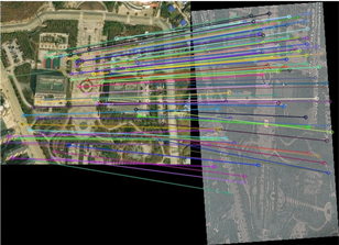
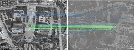
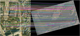
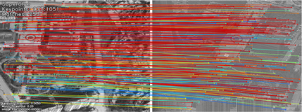
After the reference image acquisition, feature matching was carried out. Some of the results are compared with the original SuperPoint + SuperGlue results in Table 1. In both the “Ours” and “SuperGlue” columns, the left images are the reference image clips automatically obtained from the online map service, and the right images are the sensed UAV images. The colored lines in the images represent the matching relationships between corresponding points in two images.

Table 1.
Comparisons between our feature matching results and SuperGlue’s.
As is shown by the figure, the proposed method was able to extract more than 100 good matches for the UAV imagery captured. In the meantime, the original SuperPoint + SuperGlue method was not able to extract correct matches. This was mainly due to the orientation misalignment introduced by the heading angle of the exposure station. The only exception was the image with the heading angle of 345°, since the orientation of the captured image ((d) in Figure 10) was almost the same as the reference image.
Please note that for the 180° and 266° images, the matching lines in the original SuperGlue result are actually wrong matches, meaning that SuperGlue failed when there was an obvious orientation error between the sensed image and the reference image.
The images captured could then be rectified. The results are shown in Figure 14.
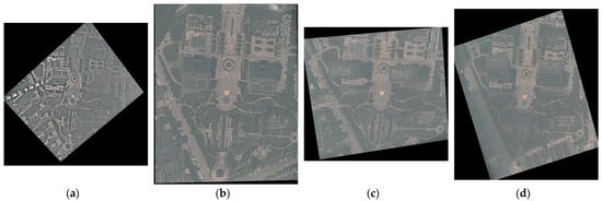
Figure 14.
Geometric rectification results. The heading angles(in degrees) of the original sensed images are: (a) 51, heading northeast; (b) 180, heading south; (c) 266, heading east; and (d) 345, heading northwest.
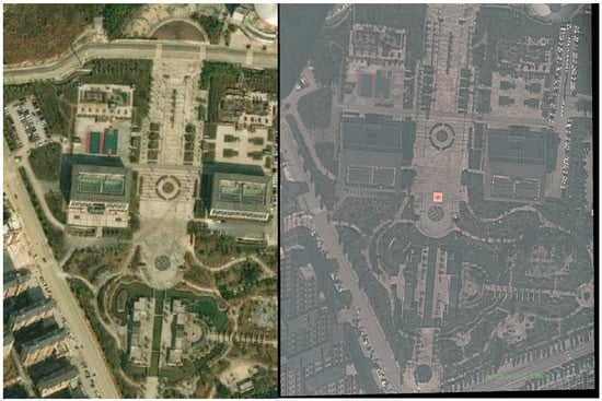
Figure 15.
Enlarged version of the reference image and the result image of Figure 14b.
The geometry accuracies of the results were also checked by manually selecting 10 checking points from the reference image and calculating the root mean square error (RMSE) of the checking points. See Figure 16 for the checking points’ distribution in the image of Figure 14a. For the images of Figure 14b–d, at least 10 checking points evenly distributed within the images were selected.
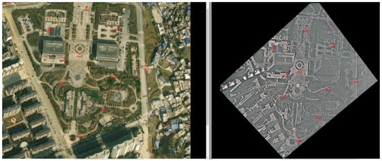
Figure 16.
Checking points’ distribution in image (a).
The RMSE of the four geometric rectified images are shown in Figure 17. As can be seen from the figure, three out of the four images have an RMSE of less than 3 m. Image (a) has a RMSE of 5.2 m, which is due to the fact that the right side of the rectified image has a bad quality because of the existence of thin clouds or mist.
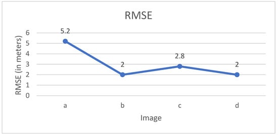
Figure 17.
RMSE of the rectified images.
For fields like disaster relief and rescue, an RMSE of less than 3 m is acceptable, especially from a distance of 15,000 m. In fact, the imaging distance for many scenarios may be only a few kilometers or even less; this will lead to a better geometric accuracy than that of the data used in this paper. Another factor that also needs to be pointed out is that the tilt angle of the images is about 65°, which is quite a big tilt angle since for many applications vertical images can be captured. Vertical images will lead to better geometric rectification accuracy since the geometric distortion between the reference image and the sensed image will be smaller and the accuracy of the matched features will be higher.
In conclusion, with the automatically obtained reference image, the proposed framework was able to carry out orientation alignment, feature matching, and geometric rectification, and the accuracy of the result image was only a few meters. This demonstrates that the proposed framework is able to carry out fully automatic geometric registration with promising accuracy.
5. Discussion
As has been discussed in Section 3, the proposed framework is able to carry out fully automatic UAV image geometric registration based on online image services and a POS, which can greatly improve efficiency. We actually did not carry out any time consumption comparison between the proposed method and the traditional methods. However, our experience indicates that at least a couple of minutes is needed for it to estimate ground range and to acquire corresponding reference images, not to mention in scenarios where it is not known where a reference image can be found. In the meantime, these processes can be performed in less than 10 s with the proposed method as long as internet access is available.
We also discussed the accuracy of the ground range estimation in the paper. However, it should be noted that estimation accuracy depends on sensors, as well as their calibration. In other words, as long as proper calibration is performed for the sensors, a sufficient estimation accuracy can always be expected. Camera calibration can even be carried out during the process as georeferencing goes on to obtain an even better estimation accuracy. In addition, the estimated range can be slightly extended, so the ground area can always be fully covered even when there are minor estimation discrepancies.
Rotation was chosen as the orientation alignment method in this paper; this is because studies show that the heading angle has an obvious effect on the matching process for SuperPoint’s features. This does not mean that rotation is the only option in the proposed framework. In fact, rotation, perspective transformation, DG, or any other correction that a POS enables can be chosen, based on the need of the feature match method being used.
We did not pay too much attention to the feature match steps, for example how fast they were and how good the matching results were. This is because the purpose of the paper was to propose a fully automatic workflow in which SuperPoint + SuperGlue can be chosen as the feature match scheme, as well as any other preferred feature match methods.
The proposed framework can also be applied to satellite imagery, as long as ground range and resolution estimation is carried out using rational polynomial coefficient (RPC) parameters instead of a POS, which is similar to a method that we conducted years ago []. Orientation alignment is also possible; a simple way of performing this is to carry out systematic rectification using the RPC provided.
6. Conclusions
A fully automatic geometric registration framework of UAV imagery based on online image services and POS information is proposed in this paper. The main idea of the proposed framework is to carry out automatic reference image acquisition by using an online map service and carry out automatic ground range and resolution estimation and geometric registration by using a POS. It has been demonstrated by our experiments that the proposed method is able to acquire reference images automatically with the right ground range and resolution. It has also been demonstrated that orientation alignment using a POS significantly improves the reliability of the image matching process. Most importantly, a fully automatic UAV imagery geometric registration without manual interference such as reference image acquisition was demonstrated to be possible using the proposed framework. This will bring obvious improvement to the time efficiency of UAV imagery’s geometric registration and will be meaningful in emergency response scenarios.
However, due to the limitations of the feature matching method used, multi-model image pairs (such as optical-synthetic aperture radar (SAR) image pair) may pose challenges to the method. So, a multi-model image matching technique may be researched in the future. Please note that this is a limitation of the image matching method used, not a limitation of the proposed framework.
Author Contributions
Conceptualization and software, P.L.; methodology, P.L. and K.S.; validation and investigation, Y.W.; formal analysis, Y.W.; resources, H.S.; data curation, Y.Z.; writing—original draft preparation, Y.Z.; writing, review and editing, Y.C.; visualization, Y.C.; supervision, T.B. and K.S.; project administration, H.S.; funding acquisition, P.L. and Y.C. All authors have read and agreed to the published version of the manuscript.
Funding
This research was funded by the Foundation of State Key Laboratory of Geo-Information Engineering, China (No. SKLGIE2023-M-3-2), the Natural Science Foundation of China (NO.42301457), and the Scientific Research Foundation for Doctoral Program of Hubei University of Technology, grant number BSQD2020065.
Data Availability Statement
Data underlying the results presented in this paper are not publicly available at this time but may be obtained from the authors upon reasonable request.
Conflicts of Interest
The authors declare no conflicts of interest.
References
- Abdollahi, A.; Pradhan, B.; Shukla, N.; Chakraborty, S.; Alamri, A. Deep Learning Approaches Applied to Remote Sensing Datasets for Road Extraction: A State-Of-The-Art Review. Remote Sens. 2020, 12, 1444. [Google Scholar] [CrossRef]
- Yang, Z.; Yu, X.; Dedman, S.; Rosso, M.; Zhu, J.; Yang, J.; Xia, Y.; Tian, Y.; Zhang, G.; Wang, J. UAV remote sensing applications in marine monitoring: Knowledge visualization and review. Sci. Total Environ. 2022, 838, 155939. [Google Scholar] [CrossRef] [PubMed]
- Asadzadeh, S.; de Oliveira, W.J.; de Souza Filho, C.R. UAV-based remote sensing for the petroleum industry and environmental monitoring: State-of-the-art and perspectives. J. Pet. Sci. Eng. 2022, 208, 109633. [Google Scholar] [CrossRef]
- Wasehun, E.T.; Hashemi Beni, L.; Di Vittorio, C.A. UAV and satellite remote sensing for inland water quality assessments: A literature review. Environ. Monit. Assess. 2024, 196, 277. [Google Scholar] [CrossRef]
- Sankey, T.T.; Tango, L.; Tatum, J.; Sankey, J.B. Forest fire, thinning, and flood in wildland-urban interface: UAV and lidar-based estimate of natural disaster impacts. Landsc. Ecol. 2024, 39, 58. [Google Scholar] [CrossRef]
- Ahmad, R. Smart remote sensing network for disaster management: An overview. Telecommun. Syst. 2024, 87, 213–237. [Google Scholar] [CrossRef]
- Yao, H.; Qin, R.; Chen, X. Unmanned Aerial Vehicle for Remote Sensing Applications—A Review. Remote. Sens. 2019, 11, 1443. [Google Scholar] [CrossRef]
- Song, Z.; Zhang, Z.; Yang, S.; Ding, D.; Ning, J. Identifying sunflower lodging based on image fusion and deep semantic segmentation with UAV remote sensing imaging. Comput. Electron. Agric. 2020, 179, 105812. [Google Scholar] [CrossRef]
- Singh, A.K.; Swarup, A.; Phartiyal, G.S.; Singh, D. Computational-Vision based Orthorectification and Georefrencing for Correct Localization of Railway Track in UAV Imagery. In Proceedings of the IGARSS 2020-2020 IEEE International Geoscience and Remote Sensing Symposium, Virtual, 26 September–2 October 2020; pp. 6475–6478. [Google Scholar]
- Skaloud, J. Direct Georeferencing in Aerial Photogrammetric Mapping. Photogramm. Eng. Remote Sens. 2002, 68, 207–210. [Google Scholar]
- He, F.; Zhou, T.; Xiong, W.; Hasheminnasab, S.M.; Habib, A. Automated Aerial Triangulation for UAV-Based Mapping. Remote Sens. 2018, 10, 1952. [Google Scholar] [CrossRef]
- Osco, L.P.; Marcato Junior, J.; Marques Ramos, A.P.; de Castro Jorge, L.A.; Fatholahi, S.N.; de Andrade Silva, J.; Matsubara, E.T.; Pistori, H.; Gonçalves, W.N.; Li, J. A review on deep learning in UAV remote sensing. Int. J. Appl. Earth Obs. Geoinf. 2021, 102, 102456. [Google Scholar] [CrossRef]
- Feng, R.; Shen, H.; Bai, J.; Li, X. Advances and opportunities in remote sensing image geometric registration: A systematic review of state-of-the-art approaches and future research directions. IEEE Geosci. Remote Sens. Mag. 2021, 9, 120–142. [Google Scholar] [CrossRef]
- Xiang, H.; Tian, L. Method for automatic georeferencing aerial remote sensing (RS) images from an unmanned aerial vehicle (UAV) platform. Biosyst. Eng. 2011, 108, 104–113. [Google Scholar] [CrossRef]
- Wan, Q.; Chen, J.; Luo, L.; Gong, W.; Wei, L. Drone Image Stitching Using Local Mesh-Based Bundle Adjustment and Shape-Preserving Transform. IEEE Trans. Geosci. Remote Sens. 2021, 59, 7027–7037. [Google Scholar] [CrossRef]
- Laliberte, A.S.; Scientist, S.; Winters, C.; Rango, A. A Procedure for Orthorectification of Sub-Decimeter Resolution Imagery Obtained with an Unmanned Aerial Vehicle (UAV). In Proceedings of the ASPRS 2008 Annual Conference, Portland, OR, USA, 28 April–2 May 2008. [Google Scholar]
- Turner, D.; Lucieer, A.; Watson, C. An Automated Technique for Generating Georectified Mosaics from Ultra-High Resolution Unmanned Aerial Vehicle (UAV) Imagery, Based on Structure from Motion (SfM) Point Clouds. Remote Sens. 2012, 4, 1392–1410. [Google Scholar] [CrossRef]
- Turner, D.; Lucieer, A.; Malenovský, Z.; King, D.H.; Robinson, S.A. Spatial Co-Registration of Ultra-High Resolution Visible, Multispectral and Thermal Images Acquired with a Micro-UAV over Antarctic Moss Beds. Remote Sens. 2014, 6, 4003–4024. [Google Scholar] [CrossRef]
- Ye, Y.; Tang, T.; Zhu, B.; Yang, C.; Li, B.; Hao, S. A Multiscale Framework with Unsupervised Learning for Remote Sensing Image Registration. IEEE Trans. Geosci. Remote Sens. 2022, 60, 1–15. [Google Scholar] [CrossRef]
- Feng, G.; Jeffrey, G.M.; Robert, E.W. Automated registration and orthorectification package for Landsat and Landsat-like data processing. J. Appl. Remote Sens. 2009, 3, 033515. [Google Scholar] [CrossRef]
- Scheffler, D.; Hollstein, A.; Diedrich, H.; Segl, K.; Hostert, P. AROSICS: An Automated and Robust Open-Source Image Co-Registration Software for Multi-Sensor Satellite Data. Remote Sens. 2017, 9, 676. [Google Scholar] [CrossRef]
- Pritt, M.D.; Gribbons, M.; LaTourette, K. Automated cross-sensor registration, orthorectification and geopositioning using LIDAR digital elevation models. In Proceedings of the 2010 IEEE 39th Applied Imagery Pattern Recognition Workshop (AIPR), Washington, DC, USA, 13–15 October 2010; pp. 1–6. [Google Scholar]
- Slonecker, E.T.; Brad, J.; Joe, M. Automated imagery orthorectification pilot. J. Appl. Remote Sens. 2009, 3, 033552. [Google Scholar] [CrossRef]
- Li, P.; Sun, K.; Li, D.; Sui, H.; Zhang, Y. An Emergency Georeferencing Framework for GF-4 Imagery Based on GCP Prediction and Dynamic RPC Refinement. Remote Sens. 2017, 9, 1053. [Google Scholar] [CrossRef]
- Shang, K.; Zhao, L.; Zhang, W.; Ming, L.; Liu, C. Unmanned aerial vehicle visual localization method based on deep feature orthorectification matching. J. Chin. Inert. Technol. 2024, 32, 52–57+106. [Google Scholar] [CrossRef]
- Habib, A.; Han, Y.; Xiong, W.; He, F.; Zhang, Z.; Crawford, M. Automated Ortho-Rectification of UAV-Based Hyperspectral Data over an Agricultural Field Using Frame RGB Imagery. Remote Sens. 2016, 8, 796. [Google Scholar] [CrossRef]
- Barbieux, K. Pushbroom Hyperspectral Data Orientation by Combining Feature-Based and Area-Based Co-Registration Techniques. Remote Sens. 2018, 10, 645. [Google Scholar] [CrossRef]
- Zhang, J.; Fan, D.-P.; Dai, Y.; Yu, X.; Zhong, Y.; Barnes, N.; Shao, L. RGB-D saliency detection via cascaded mutual information minimization. In Proceedings of the IEEE/CVF International Conference on Computer Vision, Montreal, QC, Canada, 10–17 October 2021; pp. 4338–4347. [Google Scholar]
- Li, J.; Wang, P.; Xiong, P.; Cai, T.; Yan, Z.; Yang, L.; Liu, J.; Fan, H.; Liu, S. Practical stereo matching via cascaded recurrent network with adaptive correlation. In Proceedings of the IEEE/CVF conference on Computer Vision and Pattern Recognition, New Orleans, LA, USA, 18–24 June 2022; pp. 16263–16272. [Google Scholar]
- Fan, J.; Ye, Y.; Li, J.; Liu, G.; Li, Y. A novel multiscale adaptive binning phase congruency feature for SAR and optical image registration. IEEE Trans. Geosci. Remote Sens. 2022, 60, 1–16. [Google Scholar] [CrossRef]
- Yuan, W.; Yuan, X.; Cai, Y.; Shibasaki, R. Fully automatic DOM generation method based on optical flow field dense image matching. Geo-Spat. Inf. Sci. 2023, 26, 242–256. [Google Scholar] [CrossRef]
- Yu, Q.; Ni, D.; Jiang, Y.; Yan, Y.; An, J.; Sun, T. Universal SAR and optical image registration via a novel SIFT framework based on nonlinear diffusion and a polar spatial-frequency descriptor. ISPRS J. Photogramm. Remote Sens. 2021, 171, 1–17. [Google Scholar] [CrossRef]
- Merkle, N.; Auer, S.; Mueller, R.; Reinartz, P. Exploring the potential of conditional adversarial networks for optical and SAR image matching. IEEE J. Sel. Top. Appl. Earth Obs. Remote Sens. 2018, 11, 1811–1820. [Google Scholar] [CrossRef]
- Hughes, L.H.; Schmitt, M.; Zhu, X.X. Mining hard negative samples for SAR-optical image matching using generative adversarial networks. Remote Sens. 2018, 10, 1552. [Google Scholar] [CrossRef]
- DeTone, D.; Malisiewicz, T.; Rabinovich, A. SuperPoint: Self-Supervised Interest Point Detection and Description. In Proceedings of the 2018 IEEE/CVF Conference on Computer Vision and Pattern Recognition Workshops (CVPRW), Salt Lake City, UT, USA, 18–22 June 2018; pp. 337–33712. [Google Scholar]
- Arar, M.; Ginger, Y.; Danon, D.; Bermano, A.H.; Cohen-Or, D. Unsupervised multi-modal image registration via geometry preserving image-to-image translation. In Proceedings of the IEEE/CVF Conference on Computer Vision And Pattern Recognition, Seattle, WA, USA, 13–19 June 2020; pp. 13410–13419. [Google Scholar]
- Hughes, L.H.; Marcos, D.; Lobry, S.; Tuia, D.; Schmitt, M. A deep learning framework for matching of SAR and optical imagery. ISPRS J. Photogramm. Remote Sens. 2020, 169, 166–179. [Google Scholar] [CrossRef]
- Ren, Y.; Liu, Y.; Huang, Z.; Liu, W.; Wang, W. 2chADCNN: A Template Matching Network for Season-Changing UAV Aerial Images and Satellite Imagery. Drones 2023, 7, 558. [Google Scholar] [CrossRef]
- Sarlin, P.-E.; DeTone, D.; Malisiewicz, T.; Rabinovich, A. SuperGlue: Learning Feature Matching With Graph Neural Networks. In Proceedings of the 2020 IEEE/CVF Conference on Computer Vision and Pattern Recognition (CVPR), Seattle, WA, USA, 14–19 June 2020; pp. 4937–4946. [Google Scholar]
- ESRI. World Imagery. Available online: https://www.arcgis.com/home/item.html?id=10df2279f9684e4a9f6a7f08febac2a9 (accessed on 7 December 2023).
Disclaimer/Publisher’s Note: The statements, opinions and data contained in all publications are solely those of the individual author(s) and contributor(s) and not of MDPI and/or the editor(s). MDPI and/or the editor(s) disclaim responsibility for any injury to people or property resulting from any ideas, methods, instructions or products referred to in the content. |
© 2024 by the authors. Licensee MDPI, Basel, Switzerland. This article is an open access article distributed under the terms and conditions of the Creative Commons Attribution (CC BY) license (https://creativecommons.org/licenses/by/4.0/).