Abstract
This study investigates the cooperative transport of a cable-suspended payload by two multirotor unmanned aerial vehicles (UAVs). A compact nonlinear control law that allows to simultaneously (i) track a slow reference trajectory, (ii) hold a prescribed inter-vehicle geometry, and (iii) actively damp load swing is developed. The model treats the two aerial robots and the payload as three point masses connected by linear-elastic cables, and the controller is obtained through a Newton–Euler formulation. A singular-perturbation analysis shows that, under modest gain–separation conditions, the closed-loop system is locally exponentially stable: fast dynamics govern formation holding and swing suppression, while slow dynamics takes into account trajectory tracking. Validation is performed in a realistic simulation scenario that includes six-degree-of-freedom rigid-body vehicles, Blade-Element theory rotor models, and sensor noise. Compared to an off-the-shelf, baseline controller, the proposed method significantly improves flying qualities while minimizing hazardous payload oscillations. Owing to its limited parameter set and the absence of heavy optimization, the approach is easy to tune and well suited for real-time implementation on resource-limited UAVs.
1. Introduction
Over the past decade, multirotor platforms have become the dominant choice in small-scale unmanned aviation. Their minimalist airframe, wide control authority, and ability to dart through cluttered spaces make them the best choice for tasks as varied as aerial cinematography, infrastructure inspection, precision farming, policing, and last-mile logistics [,]. Continuing advances in electric propulsion and compact, high-performance avionics have only reinforced this trend.
Two payload-handling strategies dominate the emerging Air Mobility and Delivery (AMD) landscape. The first mounts the cargo in a rigid gripper or a belly bay. Although mechanically straightforward, the added mass and structural complexity erode flight endurance and agility [,]. The second strategy suspends the payload on one or more tethers. This lightweight solution preserves vehicle performance and eases airframe design, but it also introduces under-actuated swing dynamics that can destabilize the aircraft or damage the load [,].
Many efforts have tackled swing suppression in single-agent systems. In [], the authors explore the effect of dynamic load disturbances introduced by an instantaneously increased payload mass and how this affects a quadrotor under proportional–integral–derivative flight control. In [], the authors develop an adaptive controller to respond to changes in the multirotor center of gravity. Another adaptive control method for a quadrotor transporting a payload connected through a flexible cable is presented in []. The cable is modeled as a set of serially connected rigid links and the payload is described as a point–mass. A hybrid approach is investigated in [] to model the multirotor–payload system and handle wire collapse, provided that trajectory controllers stabilize the load position in 2D environment. A nested saturation controller to stabilize the system and control the oscillations is proposed in []. In such a framework, the control law guarantees asymptotic stability without any restrictions on the position and velocity of the aerial vehicle. In [], the authors introduce a nonlinear controller to stabilize the quadrotor and the load during positioning and trajectory-tracking tasks. Input-shaping has long been exploited to tailor reference trajectories that suppress residual swing during aggressive maneuvers []. More recently, one of the present authors proposed a two-tier architecture in which a set of inner-loop controllers guarantees the nominal hover dynamics of a single multirotor, while auxiliary outer-loop laws reshape the closed-loop behavior once a cable-suspended load is attached, explicitly damping the oscillatory mode [].
When payload mass grows or mission resilience is paramount, a single vehicle is inadequate and cooperative lifting is required. Michael et al. [] introduced an early PID-based strategy for two quadrotors linked to a common payload; although straightforward, their controller left the lightly damped swing largely unmitigated. Bacelar et al. [] advanced the field by pairing an LQR regulator with a Kalman filter and validating the scheme on two commercial platforms instrumented with ultrasonic altimeters, IMUs, and forward-looking cameras. Ariyibi et al. [] adopted a hierarchical design: a linear outer position loop sits atop a quaternion-based nonlinear attitude loop, and the approach was tested in simulation for both rigid and flexible tethers. Klausen et al. [] tackled unknown payload masses and environmental disturbances through a decentralized algorithm that relies solely on inter-agent position and velocity measurements to reach the desired formation. Finally, Tognon et al. [] presented a Lyapunov-based decentralized controller for two aerial robots engaged in cooperative manipulation of a cable-suspended load, further underscoring the trend toward distributed architectures in aerial co-transport.
Yet, no single approach simultaneously addresses formation geometry, trajectory tracking, swing damping, and adaptability across various rotary-wing platforms. Recent studies begin to fill these gaps. In [], the authors propose an obstacle-aware, event-triggered distributed Nonlinear Model Predictive Control (NMPC) scheme that dynamically balances global planning and real-time load control during cooperative transportation. A trajectory-based full-pose motion planner for agile, whole-body multi-robot maneuvers through narrow passages is developed in [], where the aerial agents can achieve accelerations up to eight times greater than state-of-the-art methods. In [], the authors presented Auto-Multilift, a learning-augmented distributed model predictive control (MPC) that auto-tunes hyperparameters through deep neural networks for scalable multi-agent load tasks. In [] a robust integral of the sign of the error (RISE) controller is integrated with model-reference adaptation in virtual-structure formations. Numerical simulations and experimental results demonstrate the effectiveness of the method, leading to improved trajectory tracking and showing strong disturbance rejection capabilities.
The present work contributes a compact control strategy that recasts cooperative transportation as a formation-stabilization problem, treating payload swing as an external disturbance. Starting from the results of a recent work by some of the authors [], a formation control scheme is proposed for two agents with the aim to cooperatively perform trajectory-tracking and formation geometry-keeping with the additional stabilization of the oscillatory dynamics. Stemming from the idea presented in [], controller gains are designed so that the loaded formation exhibits a two-time-scale behavior: the fast dynamics develops with simultaneous formation geometry stabilization and payload swing damping, while the slow dynamics is related to the trajectory-tracking task. Under these conditions, stability and gain tuning are based on singular perturbation and conservative Lyapunov criteria [], allowing practical relaxation of time-scale separation.
The controller is derived under a clear set of assumptions: each aircraft and the payload are treated as point masses within a Eulerian framework. To gauge the realism of these idealizations, we run high-fidelity simulations on two electric octarotors whose propellers are captured by blade-element theory. The scenario emulates parcel-delivery flights through a challenging environment that combines visco-elastic cables, parameter uncertainty, sensor noise, and a wireless link subject to latency and occasional packet loss. Although the closed-loop dynamics are strongly nonlinear, the resulting control law is compact, physically meaningful, and well suited for on-board implementation. The built-in two-time-scale separation also fulfills a practical requirement of slung-load operations: precise path-tracking commences only after the payload oscillations have been swiftly attenuated.
It is acknowledged that the proposed control method has some limitations. First, the algorithm may lose accuracy under extreme flight conditions involving highly aggressive maneuvers and cables becoming slack. However, these scenarios fall outside the intended scope of the present work, which focuses on envisaging future air mobility and delivery applications. In this respect, flight trajectories are required to be smooth and conservative to avoid damaging the payload and the surrounding environment. Second, while extending this method to different UAV configurations is straightforward, scalability to formations of more than two vehicles introduces actuation redundancy and demands further mathematical investigation. Nevertheless, focusing on the dual-vehicle case keeps the method computationally lightweight and directly applicable to current hardware.
2. Problem Statement and Solution
The cooperative–transport task is first formulated under the common point-mass assumption: each UAV and the payload are treated as three degrees-of-freedom particles. After the control problem is laid out, the numerical study relaxes the hypothesis by modeling the i-th multirotor as a rigid body whose center of gravity is . Both vehicles and the suspension cables share identical geometric and inertial properties.
2.1. Reference Frames
Three right-handed orthogonal frames are used throughout:
- (a)
- Earth frame —a North–East–Down triad with origin fixed on the Earth’s surface. The axes point to geodetic north, east, and downward, respectively. A flat, non-rotating Earth renders this frame inertial for the present purposes.
- (b)
- Body frames , —attached to each vehicle at its center of gravity. The axis runs out the nose, toward the belly, and completes the right-handed set.
- (c)
- Structural frame , —used for component layout. It is parallel to but flips the longitudinal and vertical axes: , , . Stations () are positive aft, buttlines () positive starboard, and waterlines () positive upward.
A sketch of the i-th UAV including the selected reference frames is reported in Figure 1.
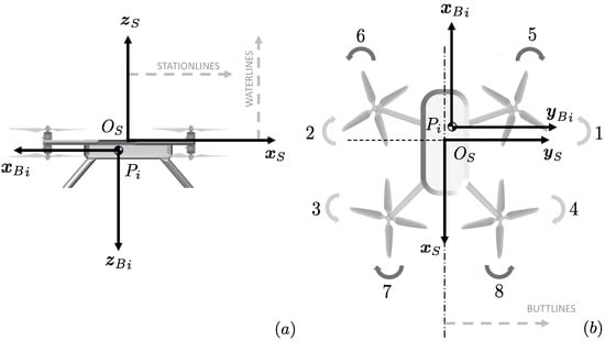
Figure 1.
Multirotor body-fixed reference frames from (a) lateral and (b) top views.
Let and . Vector transformation between and is provided by the rotation matrix []
where describes the attitude of the i-th vehicle in terms of classical ‘roll’, ‘pitch’, and ‘yaw’ angles. Vector rotation is obtained by an intrinsic 3–2–1 Euler rotation sequence according to . Positive rotations follow the right-hand rule about the current axes , , and , respectively. For simplicity, the subscript E will be omitted in what follows.
2.2. Equations of Motion
Define the position and velocity of the i-th multirotor with respect to the inertial frame as and , respectively. A suspended load with mass is connected in by a cable to the i-th multirotor, as depicted in Figure 2.
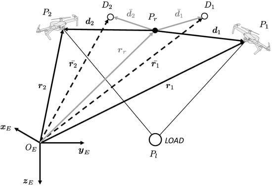
Figure 2.
Definition of current () and desired () position of the i-th agent.
The dynamics of each agent as expressed in is described by the following equations:
where m is mass of the aerial vehicle, is local gravitational acceleration vector, is vehicle aerodynamic drag, and is the force induced by the load on the i-th UAV through the cable. The total thrust vector , directed along and pointing upwards, represents the only control input to Equation (3). Provided is air density, principally accounts for the contribution of UAV frame, for which a simple flat-plate area model is proposed,
where , , and are the equivalent flat plate drag areas facing the three body-frame axes of the i-th agent.
It is assumed that the i-th cable is directly connected to the center of gravity of the i-th multirotor, such that has no effect on attitude motion. Payload dynamics is described by Newton–Euler equations projected in , namely:
where is payload velocity and is the payload aerodynamic force, obtained as
provided is payload drag coefficient and is a reference area for drag computation. Each cable is mass-less and its aerodynamic drag is disregarded. Let be the position of the load, obtained from
The vector describing the orientation and length of the i-th cable is . According to Hookes’ model, the force is calculated from the linear–elastic equation
where K is elastic constant, L is nominal cable length, is elastic deformation, and .
2.3. Formation Modeling
Let the i-th vehicle be tasked with maintaining a prescribed distance from a reference point , which is defined by its position vector and velocity . The desired position of the i-th vehicle, denoted by , is specified by the vector (refer to Figure 2). This leads to
and
where and , respectively, indicate the current and the required relative distance between the i-th agent and the reference point. The following equation is derived:
Define . Considering Equation (2) and taking the time derivative of Equation (11) one obtains
with being the i-th vehicle desired velocity. Assuming that the latter, , matches the velocity of the reference point, , the relative position dynamics of the i-th vehicle with respect to the reference point can be expressed as:
Define and as the relative position and trajectory error variables, respectively. By taking into account Equations (3) and (13), formation error dynamics results in
The formation error dynamics defined above is extended to account for the residual degree of freedom related to payload oscillation. Let G be the center of gravity of the complete system with total mass made of multirotors and payload, with position:
Assume the center of gravity G is also required to track the reference point , such that is an error vector. Let , such that
Based on the definition of G in Equation (16), the dynamics of is derived from Equations (3) and (5) as
With this in mind, the i-th elastic disturbance term defined in Equation (8) and affecting Equation (15) is be conveniently expressed as a function of errors and . To this end, payload position is first expressed as a function of r from Equation (16):
Taking into account Equation (9) and the definitions of formation error vectors, it follows and for . By substitution into Equation (19) one has
and the vector directed from UAV 1 to the payload becomes
Similarly, for UAV 2 is:
2.4. Formation Control
The present section outlines the design of a controller to simultaneously perform (1) formation keeping, (2) trajectory tracking, and (3) load swing stabilization. The application framework is defined by Assumption 1.
Assumption 1.
It is supposed that:
- each vehicle has knowledge of both position and velocity of other objects in the formation, including the payload;
- inner-loop autopilot systems allow the i-th agent to track the desired control force with sufficient accuracy;
- the controller is generated by disregarding the aerodynamic drag affecting both the UAVs and the payload.
Remark 1.
The estimation of the oscillatory state of the payload in the cooperative scenario is a challenging issue that was recently solved by the authors of the present work in []. Stemming from the approach in [], a method was derived to estimate the swing angle and rate in cooperative multirotor suspended-load systems relying only on the onboard IMU, without any extra sensors. In this novel approach, accelerometer data and dynamic model information are fused through a Fading Gaussian Deterministic (FGD) filter, whose theoretical framework ensures the best compromise between model uncertainties and measurement noise. However, other methods based on current technology can be envisaged to perform payload state determination. They include motion capture ground systems [,], onboard visual detection devices [,], or sensors that are fixed with respect to the load [,,].
Remark 2.
The present work does not delve into the inner-loop problem of forcing each rotorcraft to follow a commanded thrust vector. A wide spectrum of well-established attitude controllers can accomplish that task, ranging from conventional PID laws [] and LQR designs [] to active-disturbance-rejection schemes [], back-stepping or feedback-linearised regulators [], and various sliding-mode formulations [,]. Whichever strategy is adopted, a common requirement emerges: the bandwidth of the attitude-and-thrust loop must exceed, by a comfortable margin, the bandwidth associated with cooperative load transport. Proper gain tuning, together with hard limits on commanded attitudes, angular rates and accelerations, ensures that separation. Under this premise the overall system naturally exhibits three distinct time-scales. Attitude dynamics form the fastest layer; the intermediate layer comprises formation keeping and swing damping; and the slowest layer is the trajectory-tracking mission itself (see Appendix B). The controller proposed here is expressly structured around that hierarchy.
Based on Assumption 1, a preliminary result is provided to characterize the formation geometry adopted in the present framework.
Lemma 1.
Let be the prescribed mutual distance vector between the two agents of the formation, with components expressed in . Provided are selected such that , it follows that desired formation geometry is defined by
and
where is actual cable length of loaded formation, obtained as the only real positive solution of equation:
that satisfies , where
Proof of Lemma 1.
See Appendix A. □
Consider the formation geometry described in Lemma 1. Let be the i-th extended error vector and define . Provided , the dynamics of center of gravity tracking error x and formation error z are, respectively, expressed as
and
where , ,
and
are determined from Equations (14)–(22) under Assumption A1.
Let , , , and be positive gain matrices. Define and . The following controller is proposed for :
where is the trim contribution derived according to Lemma 1, , and is a selection matrix obtained by vertical concatenation of and . Functions and are defined as
while is obtained as a solution of the implicit equation
where and .
Asymptotic stability for the origin of the closed-loop system in Equations (27)–(30) is addressed by the following theorem.
Theorem 1.
Proof of Theorem 1.
See Appendix B. □
3. Results
3.1. Simulation Setup
The proposed control method is validated through high-fidelity numerical simulations in the Matlab–Simulink environment with a 4th-order Runge–Kutta solver at a frequency of 200 Hz. The agents of the formation are two identical octarotors modeled as rigid bodies. The payload is assumed to be a point mass attached through a visco-elastic cable to a hook point , coincident to UAV center of gravity . The payload is affected by aerodynamic drag according to Equation (6), provided is frontal area of a sphere with radius m and drag coefficient . An octarotor platform is considered, characterized by a set of 4 contra-rotating propulsion units (see Figure 1). The cross-shaped planar configuration is characterized by m, m, m, and m. The most relevant system parameters are reported in Table 1.

Table 1.
Multirotor slung-load system parameters.
Rotor aerodynamics is described by the classical Blade Element Momentum Theory. For control purposes only the quadratic contributions to thrust and torque are retained, namely and , where the dimensional coefficients scale with air density according to and with . Because of the wake interference, the upper rotors (1–4) are more efficient than the lower ones (5–8), namely N/(rad/s)2 and N/(rad/s)2 []. Experimental calibration at the reference density kg/m3 gives Nm/(rad/s)2. The induced-velocity equation is solved at each time step with MATLAB’s (R2024b) fzero implementation of Dekker’s hybrid algorithm, using an initial guess of m/s []. Atmospheric properties vary with altitude according to the International Standard Atmosphere (ISA) model []. For safety, every motor command is clipped to the valid SBUS throttle range, namely 202 to 1802 counts, such that 202 corresponds to zero-throttle (no thrust) and 1802 corresponds to full throttle (maximum thrust). Each electric propulsion unit, consisting of an Electronic Speed Controller (ESC) and a brushless motor, is modeled by a first-order transfer function with time constant s. This transfer function captures the combined electrical and mechanical lags of the ESC–motor pair, mapping the saturated rotor-speed command to the actual shaft speed delivered by the motor.
The elastic force in Equation (8) is calculated from , that with respect to the classical Hookes’ model also accounts for cable internal damping by the coefficient C. Guidance, navigation, and control tasks are performed, without loss of generality, through a cascaded controller based on PX4 architecture and notation []. The control solution is assumed to stabilize the i-th multirotor according to different flight modes that include the tracking of an Earth-fixed set-point position , velocity , or acceleration (see Figure 3, where is the acceleration set-point generated by Velocity Controller). In this framework, desired acceleration for the i-th multirotor is obtained as , where is calculated according to the Cooperative Transportation Controller (CTC) in Equation (31). To get a better insight into the performance of the cooperative controller, a classical stabilization method is discussed as an alternative to the proposed solution. Taking into account Figure 3, it is assumed that set-point acceleration of vehicle i is generated by Velocity Controller (VC) rather than by cooperative transportation algorithm, namely . Provided a detailed analysis of PX4 control functions is out of the scope of the present paper, it is supposed that inner-loop stabilization of attitude parameters is performed with prescribed requirements in terms of accuracy and rapidity, according to Remark 2. Non-ideal sensor behavior is considered in terms of noise and sensor positioning errors. The on-board computer is located at m and m, with axes aligned with -axes. In order to simulate the effects of sensor noise on attitude control, zero-mean Gaussian white noise is added to each Euler angle and angular velocity measurement, with standard deviations deg and deg/s, respectively. The on-board computer generates control signals at a sampling frequency of 100 Hz (sample time s). Finally, a fixed time delay s is added to account for local processing and communication issues between the agents of the formation.
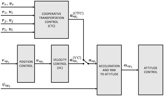
Figure 3.
i-th multirotor control scheme based on PX4 autopilot architecture [].
3.2. Performance Indicators
Indicators are defined to characterize the performance of the Cooperative Transportation Controller with respect to the standard Velocity Controller.
- Maneuver time: . It is the total time required to conclude a prescribed maneuver, according to a stop criterion. Based on the expected asymptotic nature of convergence, the maneuver is considered terminated at time when the total error falls below a certain threshold, namely .
- Average swing angle: . The oscillation angle is defined by the intersection of (i) the local–vertical plane that contains the multirotors (plane 1) and (ii) the plane that contains all the objects of the formation, including the payload (plane 2). Given and , the unit vector orthogonal to plane 2 is obtained as . The oscillation angle is retrieved as , provided is the third component of as expressed in . According to the selected convention, a positive oscillation angle is obtained from positive rotation about vector . Finally, the average swing angle is calculated as , where the integralis evaluated over maneuver time and provides an indication of how much and how long plane 2 remains inclined with respect to plane 1.
- Average swing rate: . It is calculated as , where the integralis adopted to characterize the swing rate during the entire maneuver.
- Load kinetic energy, . It is given byand provides a direct measure of residual swing and undesired motion.
- Total propulsive energy, . It is the mechanical energy delivered by electrical motors to propellers, calculated by the integralwhere is the output shaft power generated by the j-th motor, , obtained from required torque and angular rate under the assumption of null friction torque. Without loss of generality, is calculated for Agent 1 only.
3.3. Test Cases
In the following simulations, consider the formation identified by desired geometry m. With this in mind, Lemma 1 gives m, m, and m. Coefficients in Equation (26) result to be N2m2, N2m, N2, N2m, and N2m2. As predicted by theory, 4 real distinct solutions are provided (3 positive, 1 negative). The only solution that satisfies is m, related to m cable elongation. Given , one derives m from Equation (24), where kg. From Equations (A2) and (A3) it is m and m, such that the unit vectors aligned with cable 1 and cable 2 are, respectively, and . Trim forces are finally derived according to Equation (A5), where N and N. Based on simple geometric considerations, desired attitude of vehicles results to be rad, provided rad. Control gain matrices are 1/s2, 1/s, 1/s2, and 1/s. It is noted that, for the given selection of control gain matrices, the eigenvalues of H in Equation (A17) (degenerate slow subsystem) are with multiplicity 3. On the other hand, the eigenvalues of in Equation (A19) (boundary-layer fast subsystem) are given by and , both with multiplicity 6. From the former, one obtains Hz, while considering the slowest eigenvalues of the fast dynamics one has Hz. For the attitude loop, which relies on the PX4 architecture, it is safe to assume Hz []. These values support the validity of the three–time–scale separation claimed in Remark 2. With respect to Equation (38), a nonlinear system solver based on Levenberg–Marquardt method is implemented through the MATLAB R2024b routine fsolve, initialized with null first-guess solution [].
3.3.1. Test Case 1
In the first simulation test case, the multirotors start from the initial state defined by m, m, and m/s, with the payload at rest. In such equilibrium condition, payload position is given by m and formation center of gravity is identified by m. For s, the reference point is a constant equal to m, thus simulating a sample hover-to-hover maneuver.
To probe robustness, the fast subsystem gain , responsible for formation control and swing attenuation in the two-time-scale architecture, is perturbed by . The resulting trajectories are compared with the nominal Cooperative Transportation Controller and with the baseline Velocity Controller, as reported in Figure 4, Figure 5 and Figure 6. In Figure 4 the payload state is characterized in terms of oscillation angle and rate , according to the definitions provided in Section 3.2. The CTC effectively reduces the two variables when compared to the VC, showing faster convergence and increased damping.
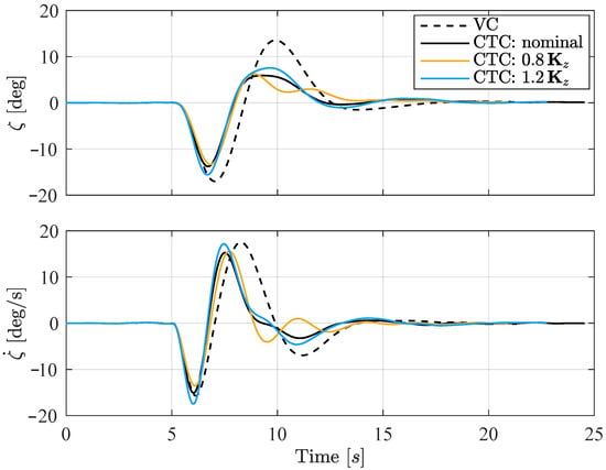
Figure 4.
Test Case 1: Oscillation angle and rate in the presence of commanded acceleration as generated by cooperative transportation controller (CTC) and velocity controller (VC).
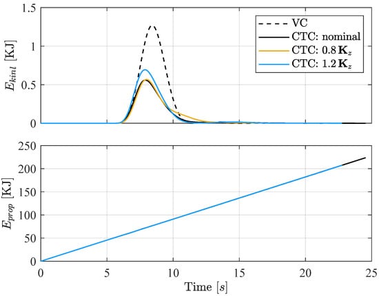
Figure 5.
Test Case 1: System energy contributions in the presence of commanded acceleration as generated by cooperative transportation controller (CTC) and velocity controller (VC).
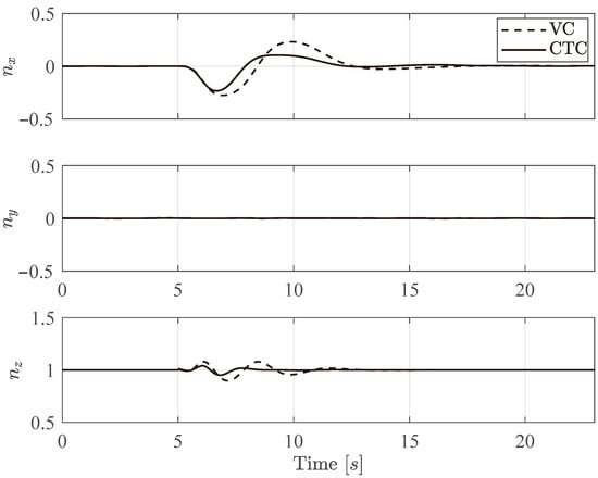
Figure 6.
Test Case 1: Load factor components along the primary translational axis in in the presence of commanded acceleration as generated by cooperative transportation controller (CTC) and velocity controller (VC).
In Figure 5 both load kinetic energy and Agent 1 propulsive energy are reported as a function of the maneuver time. The cooperative controller significantly reduces the former throughout the trajectory, indicating a substantial suppression of pendular motion. Interestingly, this improved oscillation behavior is obtained with a minimal additional energy consumption. The propulsive energy is only slightly increased compared to the velocity controller, despite the enhanced stabilization performance, due to the longer maneuver time.
Figure 4 and Figure 5 also report the results for perturbations on the fast subsystem gain . In Figure 4, the envelope formed by the (yellow) and (blue) cases basically coincides with the nominal CTC curve, confirming solid robustness under modest gain variations. In Figure 5, energy histories consolidate these findings with minimal variations with respect to the nominal controller. Together with the data in Table 2, these plots demonstrate the validity of the proposed CTC, that outperforms the baseline VC even under moderate uncertainties in the fast subsystem.

Table 2.
Test Case 1: CTC robustness to perturbations in .
To further assess the validity of the cooperative control architecture, the load factor components experienced by the suspended payload are analyzed. The load factor, defined as the ratio of the total inertial force to the gravitational force alone, is given by , providing an indication of the dynamic effort imposed on the cables and payload system. Figure 6 illustrates the time evolution of the load factor components along the primary translational axis in . These results confirm the effectiveness of the CTC in attenuating fluctuations compared to the conventional velocity controller. This reduction in load factor excursions directly correlates with a decrease in payload oscillation and tension variability along the suspension cables. The outcome demonstrates the controller’s ability to stabilize the suspended mass while preserving formation and tracking performance, thereby enhancing both safety and reliability during transport operations. Finally, Table 3 summarizes the most relevant performance indicators for the first simulation test case.

Table 3.
Test Case 1: Relevant performance indicators.
3.3.2. Test Case 2
In the second test case, the formation is required to track a sequence of six waypoints , . Following from the formulation of Section 2.3, the i-th vehicle’s desired position is based on the reference point trajectory and is given by . Without loss of generality, a waypoint is considered to be reached when the positioning error of Agent 1, defined as , remains below m for at least 5 s. This simulation scenario envisages a sample urban parcel-delivery mission as detailed in Table 4.

Table 4.
Test Case 2: Waypoints of the delivery mission.
Figure 7 depicts the reference and the multirotors trajectories over the horizontal plane – for the two control strategies, both of which achieve accurate waypoint tracking. Despite receiving an acceleration setpoint rather than a direct position setpoint as reference input, the CTC allows for slightly smoother transitions, especially near abrupt path changes, suggesting enhanced formation coordination.
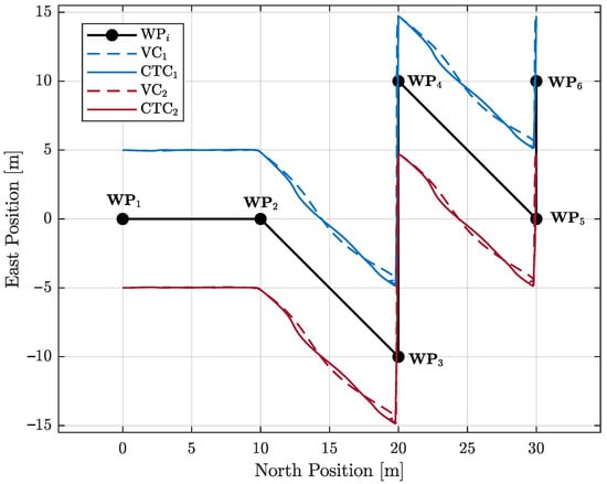
Figure 7.
Test Case 2: Delivery mission over the horizontal plane – in the presence of commanded acceleration as generated by velocity controller (VC) and cooperative transportation controller (CTC).
In Figure 8 the temporal evolution of the swing state is reported. The cooperative methodology reduces both the peak amplitude and the duration of oscillations during and after each maneuver, particularly evident around 0 s, 20 s, and 50 s. The results demonstrate that the proposed controller attenuates payload swing far more effectively than the baseline scheme, yet preserves path-following accuracy. Such improvements are critical in practical delivery tasks, where minimizing payload motion enhances safety, reliability, and energy efficiency. Test Case 2 is specifically designed to emulate a typical aerial delivery mission: the formation is required to follow a sequence of waypoints while concurrently damping the pendular motion of the suspended mass. The observed performance therefore satisfies the principal requirements of current unmanned logistics practice. Quantitative metrics are presented in detail in Table 5.
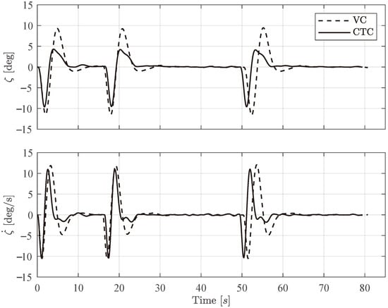
Figure 8.
Test Case 2: Oscillation angle and rate in the presence of commanded acceleration as generated by cooperative transportation controller (CTC) and velocity controller (VC).

Table 5.
Test Case 2: Relevant performance indicators.
4. Conclusions
The study has presented a cooperative–transport methodology that enables two aerial robots to follow a prescribed trajectory while actively damping the oscillation of a slung-load. By framing the problem as a formation-control task and designing the feedback loops on two well-separated time scales, rapid suppression of swing state and accurate waypoint tracking are achieved. Numerical simulations, carried out with high-fidelity propulsion models, sensor noise, and parameter uncertainty, show the effectiveness of the nonlinear Cooperative Transportation Controller in reducing both the oscillation angle and rate. In contrast, the same mission executed with a conventional Velocity Controller suffers a clear degradation in those metrics, underscoring the practical advantages of the proposed scheme. The control law depends on only a handful of easily measured parameters and admit a clear physical interpretation, making the method readily extendable to different UAV configurations. Finally, the results of singular perturbation theory allow for a preliminary control gain sizing according to the proposed two-time-scale architecture.
Author Contributions
Conceptualization, E.C. and E.L.d.A.; methodology, E.C. and E.L.d.A.; software, E.C. and E.L.d.A.; validation, E.C., E.L.d.A. and F.G.; formal analysis, E.C., E.L.d.A. and F.G.; investigation, E.C. and E.L.d.A.; resources, E.C., E.L.d.A. and F.G.; data curation, E.C., E.L.d.A. and F.G.; writing—original draft preparation, E.L.d.A.; writing—review and editing, E.C., E.L.d.A. and F.G.; visualization, E.L.d.A. and F.G.; supervision, E.L.d.A. and F.G.; project administration, E.L.d.A. and F.G.; funding acquisition, E.L.d.A. and F.G. All authors have read and agreed to the published version of the manuscript.
Funding
This study was carried out within the MOST Sustainable Mobility National Research Center and received funding from the European Union Next-GenerationEU (PIANO NAZIONALE DI RIPRESA E RESILIENZA (PNRR)—MISSIONE 4 COMPONENTE 2, INVESTIMENTO 1.4–D.D. 1033 17/06/2022, CN00000023). This manuscript reflects only the authors’ views and opinions, neither the European Union nor the European Commission can be considered responsible for them.
Data Availability Statement
The raw data supporting the conclusions of this article will be made available by the authors on request.
Conflicts of Interest
The authors declare no conflicts of interest.
Appendix A. Proof of Lemma 1
The hypotheses in Lemma 1 and the definition of error uniquely determine desired formation geometry, which is depicted in Figure A1. The condition in which each vehicle reaches the desired position (, , ) and the formation center of gravity G exactly tracks (, ), implies that , , , and G lie all on a local vertical plane. In this case, the relative distance vectors and are organized according to a symmetric configuration that makes the derivation of results in Equation (23) straightforward. In order to evaluate and , the equilibrium of forces acting on the payload along the local vertical is analyzed. To this end, let be the i-th elastic force intensity in the equilibrium condition (see Equation (8)), where and are, respectively, desired cable elongation and length. Taking into account Equation (5), it is
where is the desired cable inclination with respect to the local vertical, with . Then, Equation (A1) provides, after manipulation, Equations (25) and (26). Provided , which occurs for values of practical application, the sequence of signs for the polynomial in Equation (25) is . According to Descartes’ rule, three real positive solutions and one real negative solution are derived []. The only positive solution which is representative of the case where and the payload lies below the UAV is the largest one, which can be determined analytically or by means of a root-finding numerical algorithm [,].
Let be cable orientation vector in the equilibrium condition. From Equation (21) it is
and
It is noted that parameter in Figure A1 represents the third component of both and . With this in mind, Equation (A2) provides
with the knowledge that . By equating the right-hand side of Equation (A4) to the expression of c obtained from the analysis of right triangles in Figure A1, one finally derives the result in Equation (24).
As a by-product of Lemma 1, the trim control forces and required for the UAV to maintain the considered formation geometry are also derived. Static equilibrium from Equation (3) gives:
where is calculated for by taking into account Equations (A2) and (A3).
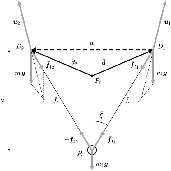
Figure A1.
Desired formation geometry (relative distance a is assigned).
Appendix B. Proof of Theorem 1
Firstly, the exponential stability of is addressed in the case when . Equations (27)–(30) with the control law in Equations (31)–(38) provide:
and
Taking into account Equations (21) and (22), and the results obtained in Assumption A1, it can be shown that the latter equation simply becomes
where are, respectively, given by
and
where and
Suppose that the gain matrices and are chosen so that the closed-loop dynamics naturally separate into two distinct time scales. In this framework, formation-keeping and payload swing damping evolve on to the fast dynamics is considered, whereas trajectory tracking is related to the slow one. Consequently, the state vectors x and z collect the slow and fast variables, respectively. Note further that the control input in Equation (38) depends only on the slow state, namely and . Under these assumptions, the system in Equations (27), (28), (A6) and (A8) can be recast in the two-time-scale standard form
where the artificial parameter (whose nominal value is 1) identifies z as the fast variable, according to the forced singular perturbation method described in [,]. Stemming from the singular-perturbation framework of Theorem 11.4 in [], one can establish exponential stability for the origin of the closed-loop model introduced in Equations (A12) and (A13). First, note that the reduced vector fields vanish at the origin:
Moreover, the algebraic equation admits a unique isolated root
which satisfies by construction (see Equation (38)). Consider all relevant mappings, namely F, G, h, and their partial derivatives bounded up to the second order. The degenerate solution for is used in turn to evaluate the unperturbed problem as in
and compute the degenerate solution for . In particular, Equation (A16) becomes:
where . Because H is Hurwitz, the origin of the reduced (slow) system in Equation (A17) is exponentially stable. Introduce the change of variable and define . The boundary-layer system
assumes the form:
which is independent of x. Since is Hurwitz, the fast subsystem is likewise exponentially stable at the origin. Then, according to Theorem 11.4 in [], there exists such that for all , the origin of the nominal system in Equations (A12) and (A13) is exponentially stable.
Returning now to the complete system in Equations (27)–(30), note that it involves the extra term . Since , one still obtains and as as a consequence of Lemma 1 in [].
Remark A1.
The proof of Theorem 1 shows that the closed loop remains exponentially stable once the fast subsystem is reinstated, provided the scaling parameter ε is chosen small enough to preserve a clear separation of time-scales. In singular-perturbation language, setting gives the reduced (or degenerate) model, whereas the original, singularly perturbed formulation represents the full plant. When the origin of the reduced model is exponentially stable, Khalil’s converse-Lyapunov result (Theorem 11.4 in []) ensures that the same property extends to the full system, as long as the neglected fast dynamics evolves sufficiently quickly. While this theorem guarantees the existence of an upper bound on ε, it does not provide a recipe for computing it. Here, ε is introduced only as an analytical device; in practice, the designer controls the degree of separation by selecting appropriate feedback gains. The intermediate steps of the proof make this link explicit: by comparing the slow subsystem in Equation (A17) with the fast boundary-layer subsystem in Equation (A19), one can inspect their eigenspectra and gauge directly how a given gain set stretches the gap between the two dynamic modes.
References
- de Angelis, E.L.; Giulietti, F.; Rossetti, G.; Bellani, G. Performance analysis and optimal sizing of electric multirotors. Aerosp. Sci. Technol. 2021, 118, 107057. [Google Scholar] [CrossRef]
- Lim, D.; Kim, H.; Yee, K. Uncertainty propagation in flight performance of multirotor with parametric and model uncertainties. Aerosp. Sci. Technol. 2022, 122, 107398. [Google Scholar] [CrossRef]
- Pounds, P.E.I.; Bersak, D.R.; Dollar, A.M. Grasping From the Air: Hovering Capture and Load Stability. In Proceedings of the IEEE International Conference on Robotics and Automation, Shanghai, China, 9–13 May 2011; pp. 2491–2498. [Google Scholar] [CrossRef]
- Chen, H.; Quan, F.; Fang, L.; Zhang, S. Aerial Grasping with a Lightweight Manipulator Based on Multi–Objective Optimization and Visual Compensation. Sensors 2019, 19, 4253. [Google Scholar] [CrossRef]
- Li, X.; Zhang, J.; Han, J. Trajectory planning of load transportation with multi–quadrotors based on reinforcement learning algorithm. Aerosp. Sci. Technol. 2021, 116, 106887. [Google Scholar] [CrossRef]
- Costantini, E.; de Angelis, E.L.; Giulietti, F. Cooperative Drone Transportation of a Cable-Suspended Load: Dynamics and Control. Drones 2024, 8, 434. Available online: https://www.mdpi.com/2504-446X/8/9/434 (accessed on 20 May 2025). [CrossRef]
- Pounds, P.E.I.; Bersak, D.; Dollar, A. Stability of small–scale UAV helicopters and quadrotors with added payload mass under PID control. Auton Robot 2012, 33, 129–142. [Google Scholar] [CrossRef]
- Palunko, I.; Fierro, R.; Cruz, P. Trajectory generation for swing–free maneuvers of a quadrotor with suspended payload: A dynamic programming approach. In Proceedings of the 2012 IEEE International Conference on Robotics and Automation, Saint Paul, MN, USA, 14–18 May 2012; pp. 2691–2697. [Google Scholar] [CrossRef]
- Dai, S.; Lee, T.; Bernstein, D.S. Adaptive Control of a Quadrotor UAV Transporting a Cable–Suspended load with Unknown Mass. In Proceedings of the 53rd Conference on Decision and Control (CDC), Los Angeles, CA, USA, 15–17 December 2014; pp. 6149–6154. [Google Scholar] [CrossRef]
- Sreenath, K.; Lee, T.; Kumar, V. Geometric control and differential flatness of a quadrotor UAV with a cable–suspended load. In Proceedings of the 52nd IEEE Conference on Decision and Control (CDC), Firenze, Italy, 10–13 December 2013; pp. 2269–2274. [Google Scholar] [CrossRef]
- Nicotra, M.M.; Garone, E.; Naldi, R.; Marconi, L. Nested saturation control of an UAV carrying a suspended load. In Proceedings of the 2014 American Control Conference, Portland, OR, USA, 4–6 June 2014; pp. 3585–3590. [Google Scholar] [CrossRef]
- Pizetta, I.H.B.; Brandão, A.S.; Sarcinelli–Filho, M. Modelling and control of a PVTOL quadrotor carrying a suspended load. In Proceedings of the 2015 International Conference on Unmanned Aircraft Systems (ICUAS), Denver, CO, USA, 9–12 June 2015; pp. 444–450. [Google Scholar] [CrossRef]
- Potter, J.; Singhose, W.; Costelloy, M. Reducing swing of model helicopter sling load using input shaping. In Proceedings of the 9th IEEE International Conference on Control and Automation (ICCA), Santiago, Chile, 19–21 December 2011; pp. 348–353. [Google Scholar] [CrossRef]
- de Angelis, E.L.; Giulietti, F. Stability and control issues of multirotor suspended load transportation: An analytical closed–form approach. Aerosp. Sci. Technol. 2023, 135, 108201. [Google Scholar] [CrossRef]
- Michael, N.; Fink, J.; Kumar, V. Cooperative manipulation and transportation with aerial robots. Auton Robot 2011, 30, 73–86. [Google Scholar] [CrossRef]
- Bacelar, T.; Madeiras, J.; Melicio, R.; Cardeira, C.; Oliveira, P. On–board implementation and experimental validation of collaborative transportation of loads with multiple UAVs. Aerosp. Sci. Technol. 2020, 107, 106284. [Google Scholar] [CrossRef]
- Ariyibi, S.O.; Tekinalp, O. Quaternion–based nonlinear attitude control of quadrotor formations carrying a slung load. Aerosp. Sci. Technol. 2020, 105, 105995. [Google Scholar] [CrossRef]
- Klausen, K.; Meissen, C.; Fossen, T.I.; Arcak, M.; Johansen, T.A. Cooperative Control for Multirotors Transporting an Unknown Suspended Load Under Environmental Disturbances. IEEE Trans. Control Syst. Technol. 2020, 28, 653–660. [Google Scholar] [CrossRef]
- Tognon, M.; Gabellieri, C.; Pallottino, L.; Franchi, A. Aerial Co–Manipulation With Cables: The Role of Internal Force for Equilibria, Stability, and Passivity. IEEE Robot 2018, 3, 2577–2583. [Google Scholar] [CrossRef]
- Tasooji, T.K.; Khodadadi, S.; Liu, G.; Wang, R. Cooperative Control of Multi-Quadrotors for Transporting Cable-Suspended Payloads: Obstacle-Aware Planning and Event-Based Nonlinear Model Predictive Control. arXiv 2025, arXiv:2503.19135. [Google Scholar]
- Sun, S.; Wang, X.; Sanalitro, D.; Franchi, A.; Tognon, M.; Alonso-Mora, J. Agile and Cooperative Aerial Manipulation of a Cable-Suspended Load. arXiv 2025, arXiv:2501.18802. [Google Scholar]
- Wang, B.; Huang, R.; Zhao, L. Auto-Multilift: Distributed Learning and Control for Cooperative Load Transportation With Quadrotors. arXiv 2024, arXiv:2406.04858. [Google Scholar]
- Villa, D.K.D.; Brandão, A.S.; Sarcinelli-Filho, M. Cooperative Load Transportation with Quadrotors using Adaptive RISE Control. J. Intell. Robot. Syst. 2024, 110, 138. [Google Scholar] [CrossRef]
- de Angelis, E.L.; Giulietti, F.; Rossetti, G. Multirotor aircraft formation flight control with collision avoidance capability. Aerosp. Sci. Technol. 2018, 77, 733–741. [Google Scholar] [CrossRef]
- de Angelis, E.L.; Giulietti, F.; Pipeleers, G. Two–time–scale control of a multirotor aircraft for suspended load transportation. Aerosp. Sci. Technol. 2019, 84, 193–203. [Google Scholar] [CrossRef]
- Khalil, H.K. Nonlinear Systems, 3rd ed.; Prentice Hall: Upper Saddle River, NJ, USA, 2002; pp. 456–459. [Google Scholar]
- Costantini, E.; de Angelis, E.L.; Giulietti, F. Cooperative Transportation Using Rotorcraft: Swing State Estimation and Control. Aerosp. Sci. Technol. 2025, 167, 110713. [Google Scholar] [CrossRef]
- de Angelis, E.L. Swing angle estimation for multicopter slung load applications. Aerosp. Sci. Technol. 2019, 89, 264–274. [Google Scholar] [CrossRef]
- How, J.P.; Behihke, B.; Frank, A.; Dale, D.; Vian, J. Realtime indoor autonomous vehicle test environment. IEEE Control Syst. Mag. 2008, 28, 51–64. [Google Scholar] [CrossRef]
- Lupashin, S.; Hehn, M.; Mueller, M.W.; Schoellig, A.P.; Sherback, M.; D’Andrea, R. A platform for aerial robotics research and demonstration: The flying machine arena. Mechatronics 2014, 24, 41–54. [Google Scholar] [CrossRef]
- Zürn, M.; Morton, K.; Heckmann, A.; McFadyen, A.; Notter, S.; Gonzalez, F. MPC controlled multirotor with suspended slung load: System architecture and visual load detection. In Proceedings of the IEEE Aerospace Conference, Big Sky, MT, USA, 5–12 March 2016; pp. 1–11. [Google Scholar] [CrossRef]
- Ebrahimi, M.; Ghayour, M.; Madani, S.M.; Khoobroo, A. Swing angle estimation for anti–sway overhead crane control using load cell. Int. J. Control Autom. Syst. 2011, 9, 301–309. [Google Scholar] [CrossRef]
- Feng, Y.; Wang, J. GPS RTK Performance Characteristics and Analysis. J. Glob. Position. Syst. 2008, 7, 1–8. [Google Scholar] [CrossRef]
- Kim, Y.S.; Hong, K.S.; Sul, S.K. Anti–Sway Control of Container Cranes: Inclinometer, Observer, and State Feedback. Int. J. Control Autom. Syst. 2004, 2, 435–449. [Google Scholar]
- Paul, H.; Ono, K.; Ladig, R.; Shimonomura, K. A Multirotor Platform Employing a Three–Axis Vertical Articulated Robotic Arm for Aerial Manipulation Tasks. In Proceedings of the IEEE/ASME International Conference on Advanced Intelligent Mechatronics (AIM), Auckland, New Zealand, 9–12 July 2018; pp. 478–485. [Google Scholar] [CrossRef]
- Najm, A.A.; Ibraheem, I.K. Nonlinear PID controller design for a 6–DOF UAV quadrotor system. Int. J. Eng. Sci. Technol. 2019, 22, 1087–1097. [Google Scholar] [CrossRef]
- Rinaldi, F.; Chiesa, S.; Quagliotti, F. Linear quadratic control for quadrotors UAVs dynamics and formation flight. J. Intell. Robot. Syst. 2013, 70, 203–220. [Google Scholar] [CrossRef]
- Zhang, Y.; Chen, Z.; Sun, M.; Zhang, X. Trajectory tracking control of a quadrotor UAV based on sliding mode active disturbance rejection control. Nonlinear Anal. Model. Control 2019, 24, 545–560. [Google Scholar] [CrossRef]
- Zhou, L.; Zhang, J.; Dou, J.; Wen, B. A fuzzy adaptive backstepping control based on mass observer for trajectory tracking of a quadrotor UAV. Int. J. Adapt. Control Signal Process. 2018, 32, 1675–1693. [Google Scholar] [CrossRef]
- Gong, W.; Li, B.; Yang, Y.; Ban, H.; Xiao, B. Fixed–time integral-type sliding mode control for the quadrotor UAV attitude stabilization under actuator failures. Aerosp. Sci. Technol. 2019, 95, 105444. [Google Scholar] [CrossRef]
- Gao, B.; Liu, Y.J.; Liu, L. Adaptive neural fault–tolerant control of a quadrotor UAV via fast terminal sliding mode. Aerosp. Sci. Technol. 2022, 129, 107818. [Google Scholar] [CrossRef]
- Kim, H.W.; Brown, R.E. A Comparison of Coaxial and Conventional Rotor Performance. J. Am. Helicopter Soc. 2010, 55, 12004. [Google Scholar] [CrossRef][Green Version]
- Forsythe, G.E.; Malcolm, M.A.; Moler, C.B. Computer Methods for Mathematical Computations; Prentice–Hall: Saddle River, NJ, USA, 1976. [Google Scholar]
- NOAA-S/T 76-1562; U.S. Standard Atmosphere. U.S. Government Printing Office: Washington, DC, USA, 1976.
- PX4 Development Team and Community, PX4 Autopilot User Guide (Main). Available online: https://docs.px4.io/main/en/ (accessed on 10 April 2025).
- Press, W.H.; Flannery, B.P.; Teukolsky, S.A.; Vetterling, W.T. Numerical Recipes in C: The Art of Scientific Computing, 2nd ed.; Cambridge University Press: Cambridge, UK, 1992. [Google Scholar]
- Curtiss, D. Recent extensions of Descartes’ rule of signs. Ann. Maths 1918, 19, 251–278. [Google Scholar] [CrossRef]
- Boyer, C.B.; Merzbach, U.C. A History of Mathematics, 3rd ed.; Wiley: Hoboken, NJ, USA, 2010; pp. 255–259. [Google Scholar]
- Naidu, D.S.; Calise, A.J. Singular Perturbations and Time Scales in Guidance and Control of Aerospace Systems: A Survey. J. Guid. Control Dyn. 2001, 24, 1057–1078. [Google Scholar] [CrossRef]
- Narang–Siddarth, A.; Valasek, J. Nonlinear Time Scale Systems in Standard and Nonstandard Forms: Analysis and Control; Society for Industrial and Applied Mathematics: Philadelphia, PA, USA, 2014. [Google Scholar]
- Beard, R.W.; Lawton, J.; Hadaegh, F.Y. A Coordination Architecture for Spacecraft Formation Control. IEEE Trans. Control Syst. Technol. 2001, 9, 777–790. [Google Scholar] [CrossRef]
Disclaimer/Publisher’s Note: The statements, opinions and data contained in all publications are solely those of the individual author(s) and contributor(s) and not of MDPI and/or the editor(s). MDPI and/or the editor(s) disclaim responsibility for any injury to people or property resulting from any ideas, methods, instructions or products referred to in the content. |
© 2025 by the authors. Licensee MDPI, Basel, Switzerland. This article is an open access article distributed under the terms and conditions of the Creative Commons Attribution (CC BY) license (https://creativecommons.org/licenses/by/4.0/).