Abstract
Cross-media vehicles, which combine the advantages of airplanes and submarines, are capable of performing complex tasks in different media and have attracted significant interest in recent years. In practice, however, cross-media rotorcrafts face numerous challenges during the cross-media transition, one of which is the complex mixed air–water flows induced by their rotors operating in close proximity to the water surface. These flows can result in aerodynamic penalties and structural damage to the rotors. The interactions between a water surface and a rotor wake bring about potential risks of cross-media locomotion, which is known as the near-water effect of rotors. Given that the distinctions between the near-water effect and the ground effect of rotors are not yet widely understood, this study details the discovery of the near-water effect and provides a comprehensive review of the evolutionary development of the near-water effect, tracing its understanding from the ground effect to the influence of droplets through aerodynamic modeling, numerical simulations, and near-water experimental studies. Furthermore, open problems and challenges associated with the near-water effect are discussed, including flow field measurements and numerical simulation approaches. Additionally, potential applications of the near-water effect for the development of cross-media rotorcraft are also described, which are valuable for aerodynamic design and cross-media control.
1. Introduction
A cross-media vehicle (CMV), also referred to as a hybrid aerial–underwater vehicle (HAUV), is a novel vehicle that is specially designed to achieve repeated transitions between air and water, allowing it to operate both in air and underwater. Such vehicles possess great potential for use in ocean surveillance and as communication relays [1,2,3]. Cross-media vehicles can be categorized as multi-rotored [4,5], fixed-winged [6,7], hybrid-winged [8,9,10], and bioinspired [11]. Excitingly, in recent years, CMVs that depend on hydrofoils to glide and take-off rapidly have been developed, as shown in Figure 1.
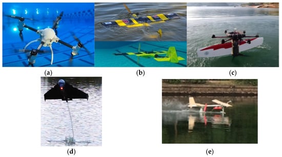
Figure 1.
Representative cross-media vehicles (CMVs): (a) multi-rotored [12]; (b) fixed-winged [7]; (c) hybrid-winged [9]; (d) bioinspired [11]; and (e) hydrofoil [13] vehicles.
Among these CMVs, multi-rotor cross-media vehicles have the advantages of a simple structure and high stability, with considerable vertical take-off and landing capability on water surfaces, which is the most efficient way to cross between these domains at present.
The strategies of cross-media locomotion based on rotors can be subdivided into continuous cross-media [5,6,14] and discontinuous cross-media [8,15] locomotion, as shown in Figure 2. Continuous cross-media locomotion usually involves using multiple rotors or a single propeller to provide upward thrust, driving the vehicle from underwater into the air directly; this cross-media method has high requirements regarding the design of the propeller blades for water–air performance balance, and a gearbox is necessary in order to cope with the low rotor speed and high torque in water and the high rotor speed and low torque in air. Such a cross-media method is commonly used in multi-rotor and fixed-wing layouts. In contrast, the discontinuous cross-media method usually uses two power systems, which work in their respective applicable media. An underwater propeller or a buoyancy control system pushes the vehicle toward the air–water interface, and a high-speed rotor is activated after it is fully exposed to the air. The discontinuous cross-media method is very common in multi-rotor and hybrid-wing layouts.
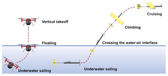
Figure 2.
Typical water exit modes for multi-rotor and fixed-wing CMVs [16].
Both of these cross-media strategies have an inevitable challenge in common: due to the presence of a fuselage, cross-media vehicles always have high draft lines, resulting in the rotor being very close to the water surface, as shown in Figure 3a.
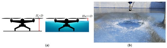
Figure 3.
(a) Schematic of near–water effect; (b) mixed air–water flows induced by rotor [17].
Experiments have demonstrated that during the cross-media transition of CMVs, the rotor operates in close proximity to the water surface, creating a large-scale multi-phase flow field composed of air, water droplets, and waves (referred to as mixed air–water flows) [17], as shown in Figure 3b. Rotors in these mixed flows exhibit completely different aerodynamic behaviors, compared to the in-ground effect (IGE) and out-ground effect (OGE) [18]. This effect is known as the NWE (near-water effect) of the rotor [17]. Unlike the IGE, which occurs when the rotor is above a rigid ground [19,20,21,22] or when fixed-wing vehicles are above either static or dynamic water surfaces [23,24,25], the rotor in the NWE operates much closer to the water interface. The rotor downwash causes significant deformation of the water surface, resulting in a large number of water droplets being generated and torn off. This interaction between the rotor blades and the deformed water surface, including the impacts of the water droplets, results in complex aerodynamic characteristics.
It is well known that research on the ground effect can be traced back to the 1930s, with the introduction of the concept of ground effect vehicles after the discovery of the special aerodynamic characteristics of aircraft approaching the ground [18]. However, few studies have been conducted on the aerodynamic characteristics of rotors and ducted fans when hovering near a water surface for an extended period, due to the slow development of CMVs. Although rotor-induced mixed air–water flows have appeared many times in many CMV flight tests [5,9,26,27], the study of the NWE has not yet gained widespread attention due to the high thrust-to-weight ratio of existing developed small CMVs. It was not until 2023 that Bai et al. [17] first experimentally investigated the rotor’s aerodynamic characteristics when close to the water surface and proposed the concept of the “near-water effect of rotor” for the first time; since then, the NWE has received increasing attention from researchers.
The motivation of this review is to address a significant yet largely overlooked phenomenon in the field of rotor aerodynamics; namely, the near-water effect. Despite its potential impact on the performance and safety of cross-media rotorcraft operating in close proximity to water, this effect has received minimal attention in the existing literature. The lack of awareness and understanding of this phenomenon has led to a critical research gap, with studies often failing to account for the influence of near-water conditions on the behavior of rotors.
This review aims to shed light on the near-water effect, emphasizing its importance and the need for further investigation. Through consolidating and analyzing the limited available research, this work seeks to highlight the implications of this effect on the design, operation, and performance of CMVs. Ultimately, the goal is to raise awareness within the research community, encouraging more comprehensive studies that incorporate the near-water effect into their analyses, thereby advancing the field and improving the safety and efficiency of CMVs.
2. Near-Water Experiments
Experimental investigation is the best way to assess new phenomena and obtain laws directly. However, as the development of CMVs is still in the small-scale stage, the mixed air–water flows induced by rotors do not seem to have a significant impact on the cross-media process; as such, they have not yet received widespread attention. As a result, there have been few experimental studies on the aerodynamic characteristics of rotors or ducted fans when hovering near a water surface to date. However, there are still some special phenomena that can be observed from flight tests. In 2019, Zha et al. [27] from the University of California carried out flight tests with a quadrotor cross-media vehicle equipped with three-bladed rotors using the discontinuous cross-media method and found that there was a delay of 0.12 s before the vehicle left the water surface when the rotor was completely above the water surface, as shown in Figure 4. Zha believed that potential causes for this delay are the time needed for propeller spin-up and the generation of turbulence on the water surface due to rotor–fluid interactions. As the control strategy produces a command signal based on the expected rotor speed and thrust, an unsteady operating medium would prevent the desired thrust from being generated, causing the observed delay to occur. Despite the lack of further analysis on the thrust loss factors and quantitative measurements, to the best of the authors’ knowledge, this study is the world’s first publicly available flight test to notice the effect of mixed air–water flows on the aerodynamic characteristics of near-water rotors.
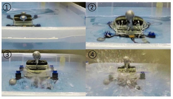
Figure 4.
Image sequence showing the mini-CMV breaching the water surface [27].
In 2023, Bai et al. [17] from the China Aerodynamic Research and Development Center carried out near-water experiments using D = 0.56 m and 0.25 m commercial rotor blades, as shown in Figure 5. The non-dimensional heights, z/R, for the water hovering condition were set from 0.1 to 4. Equation (1) is often used to calculate rotor thrust in the water and air, where T is the rotor thrust, is the density of the working medium, R is the radius of the rotor blade, ω is the angular velocity of the rotor, and CT is the thrust coefficient.
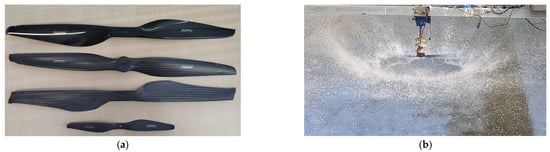
Figure 5.
(a) Tested D = 0.56 m and D = 0.25 m commercial rotor blades; (b) mixed air–water flows induced by rotor at z/R = 0.4 [17].
The main points of this study are illustrated from Figure 6a to 6c. Differing from the IGE—which is mainly affected by non-dimensional height—the NWE was significantly affected by rotor speed and rotor size as well. For D = 0.56 m blades operating at high throttle and low distances from the water surface, the NWE resulted in nonlinear increases in thrust, torque, and power, accompanied by a decrease in the rotor speed. In contrast, under low-throttle and high-distance conditions, the NWE resembled the IGE, leading to increased thrust and decreased torque, behavior that was also observed with D = 0.25 m blades at all hovering heights above the water surface. Analyzing the thrust and power performance at z/R = 0.1, as shown in Figure 6d, the NWE can be interpreted as an effect that brings little thrust increment at the expense of increased power consumption. This conclusion markedly differs from previously published numerical simulations. Bai’s initial analysis attributed this phenomenon to water surface depression, vortex rings, and droplet interactions. At low rotor heights above the water, the high-pressure zone under the rotor brings additional thrust. After the rotor wake hits the water surface, a depression is created by the downwash flow and a water surface jet develops along the radial direction. This depression can deflect the water surface jet upward, causing it to re-enter the rotor disk as inflow and prompting the rotor to enter the vortex ring state.
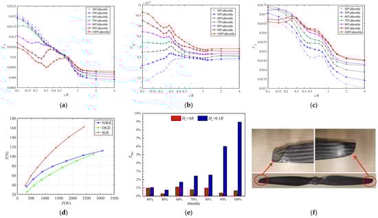
Figure 6.
Aerodynamic performance affected by near-water effect [17]: (a) thrust coefficient of D = 0.56 m blade; (b) torque coefficient of D = 0.56 m blade; (c) thrust coefficient of D = 0.25 m blade; (d) thrust versus power of D = 0.56 m blade under NEW, IGE, and OGE states at z/R = 0.1; (e) thrust fluctuation caused by droplets of D = 0.56 m blade at z/R = 0.3; (f) structural damage caused by droplets on lower wing of D = 0.56 m blade.
Observing Figure 6e, the significant thrust fluctuations effectively demonstrate the important influence of droplets on the aerodynamic characteristics of the rotor. This study suggested, for the first time, that the contribution of droplets to thrust loss cannot be ignored, in addition to vortex rings. Given the lack of reliable numerical simulations and experimental measurement techniques, and taking into account the aerodynamic impact of rainfall on aircraft, Bai preliminarily suggested that a probable mechanism for the effect of droplets on the aerodynamic performance of a near-water rotor is that an uneven water film forms on the surface, effectively increasing the surface roughness and changing the geometric configuration of the airfoil. The water film remaining on the blades after the experiment provided partial support for this perspective. Therefore, to emphasize the special situations of droplet splashing when the rotor is very close to the water surface, Bai proposed the concept of the “near-water effect”.
Furthermore, Bai tested three kinds of rotor blades with different airfoil and blade tip types and found that these factors had a significant effect on the torque characteristics of the rotor in the new context, as detailed in Table 1. Considering the transport and entrainment of sediment particles by the blade tip vortex in the helicopter brownout phenomenon, an attempt was made to use blades with winglets to reduce potential droplet entrainment; however, the winglets increased the contact area of the blade with the droplets, resulting in a significant torque increase (see Table 1). In addition to the effects on aerodynamic characteristics, the structural damage caused by droplets on D = 0.56 m carbon fiber blades was discovered for the first time, while D = 0.25 m blades remained totally intact, as shown in Figure 6e.

Table 1.
Maximal torque for different types of blades with D = 0.56 m (z/R = 0.1) [17].
The most interesting difference between the IGE and NWE is the scale effect. For large helicopters and small drones, the ground effect of rotors is basically in accordance with the law summarized by Cheeseman [28] based on the image source model, where the ground effect is only affected by the non-dimensional rotor height z/R. However, Bai’s study demonstrated that both the rotor size and rotor speed were extremely important factors in their research on the NWE, directly affecting the conclusions obtained from the experiments. To obtain a more complete understanding of the NWE, more experiments with different rotor sizes are much-needed. In 2024, Xu et al. [29] from Nanjing University of Aeronautics and Astronautics conducted near-water experiments using a D = 0.12 m three-bladed rotor blade to measure rotor thrust, torque, and speed. The non-dimensional height z/R for the water hovering condition was set in a range from 0.3 to 3.8.
As shown in Figure 7, it was found that there was always a thrust and rotor speed loss under NWE conditions: the smaller the height of the rotor above the water, the greater the thrust and rotor speed decrease. Under 90% throttle conditions, the IGE at z/R = 0.3 contributed to a maximum thrust increment of 22.5%. In contrast, the NWE induced a significantly higher maximum thrust reduction of 36.5% under the same dimensional height. Xu analyzed that many splashes interacted with the rotor to cause a reduction in rotor speed and thrust. This phenomenon can be attributed to the continuous impingement of the rotor’s high-speed downwash on the water surface. The resulting water splash modifies the properties of the surrounding air medium which, in turn, reduces the rotor speed and, consequently, its thrust output. Although the hypothesis that thrust loss is caused by alterations in the rotor’s operating medium appears plausible, sufficient quantitative analysis to fully characterize the nature and extent of these changes in the medium is currently lacking. While analyses of continuous cross-medium processes have predominantly emphasized the substantial density variations in the medium induced by blade–water impacts, as opposed to the NWE arising from rotor wake–water dynamics, the approach of characterizing changes in the medium through rotor speed variations offers valuable insights for advancing understanding of the NWE.
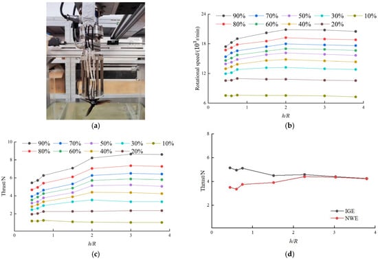
Figure 7.
(a) Test platform; (b) rotor speed characteristic with height under the NWE at different throttle settings; (c) thrust characteristic with height under the NWE at different throttle settings; (d) comparison of rotor thrust under IGE vs. NWE [29].
Notably, in 2020, Semenov [30] of the University of Maryland conducted a large number of continuous cross-media experiments using D = 0.38 m commercial rotor blades. A key contribution of this thesis is a metric named the Transition Index (TI) to estimate the “effective” density, which is defined as shown in Equation (2):
where sign denotes the Sign Function, RPM is the current rotor speed, and RPMa and RPMw are the expected rotor speeds under fully-in-air and fully-in-water conditions, respectively. During the experiments, most of the blades were located below the water surface; it was observed that the rotor splashed water into the air, and the void created by the displaced water was subsequently filled by water from below and air from above. As illustrated in Figure 8a, a portion of the splashed water remained in the vicinity of the rotor disk above the water’s free surface. During continuous cross-media transitions, the density of the medium surrounding the rotor undergoes significant variations in response to changes in the operating environment, as depicted in Figure 8b. The rotor speed exhibits notable variations due to the constrained torque output from the motor. The TI serves as an effective indicator for characterizing both the progression and extent of medium modifications within the air–water mixture environment of the rotor, as shown in Figure 8c. Upon initial contact with the water during its inbound journey, the TI value becomes non-zero, reaching a value close to 1 only when the rotor blade is fully submerged. Likewise, as the rotor exits the water, TI approaches 0 and demonstrates the carrying of water past the nominal free surface height upon its exit. The red curve in the figure shows that TI approaches zero in the process of entering the water, indicating that changes in the surrounding medium may be considered negligible when the rotor operates entirely above the water surface. Under these conditions, the reduction in rotor speed is primarily due to the variation in medium density caused by the blades partially engaging with the water.
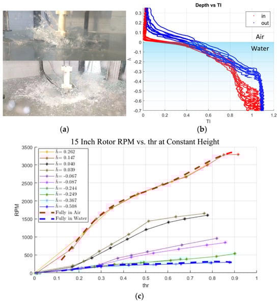
Figure 8.
(a) Image of rotor in transition (top: at low throttle, bottom: at high throttle); (b) the variance of the Transition Index as the rotor enters or exits the water at various throttle settings; (c) RPM versus throttle at various heights between fully-in-air and fully-in-water results [30].
Consequently, a comprehensive analysis of changes in the medium resulting from near-water rotor operations should incorporate quantitative analysis using TI. It is noteworthy that the magnitude of rotor speed loss exhibits considerable variation across different rotor configurations during near-water operations, in a manner dependent on rotor speed, blade size, and the number of blades. This will be covered in more detail later.
In 2024, Bi et al. [31] from Shanghai Jiao Tong University developed a bone-shaped CMV with a double-layered and staggered quadrotor configuration. During flight tests, as shown in Figure 9, they observed that the upper-layer motors are exposed to the air promptly and their thrust is limited mostly by the ceiling effect. The splashing water was observed to interfere with the normal operation of the upper-layer motors, leading to attitude vibration. The authors of this study attributed the attitude instability of the CMV to water splashing. However, their limited understanding of the NWE led them to incorrectly associate the thrust loss with the ceiling effect. Notably, the ceiling effect arises when the rotor’s upper surface is in close proximity to a boundary, enhancing the negative pressure above the rotor and increasing the pressure difference between the upper and lower wing, resulting in thrust enhancement. Evidently, the authors did not recognize that the thrust loss was induced by the NWE of the upper rotor operating above the water surface, mistakenly attributing it to the ceiling effect of the lower underwater rotor.
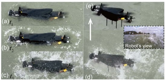
Figure 9.
Sequence diagram of cross-media locomotion [31]. (a) t1=1.82 s; (b) t2=3.47 s; (c) tc=4.84 s; (d) t4=5.82 s; (e) t6=7.00 s.
In addition to rotors, ducted fans are also commonly used to provide vertical thrust in CMVs, with the advantage of a compact layout. In 2021 and 2022, Huo et al. [32] and Nie et al. [33] from the Shenyang Institute of Automation, Chinese Academy of Sciences, fabricated and tested the world’s first tilting ducted fan CMV, as shown in Figure 10a. During a flight test, Huo unexpectedly found that the ducted fan generated a large amount of water splashing when close to the water surface. The splashes led to an unacceptable thrust loss of up to 70% at the same throttle and made it impossible for the vehicle to take-off from the water surface, as shown in Figure 10b. Huo was forced to use a segmented take-off method, in order to avoid part of the thrust loss of the ducted fan near water. This is the first time that researchers have observed ducted fans to suffer severe aerodynamic penalties when close to the water’s surface.
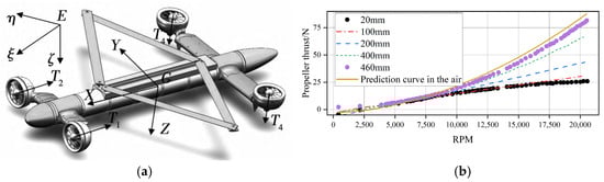
Figure 10.
(a) Tilting ducted fan CMV; (b) rotor thrust characteristics under NWE and OGE conditions [32].
Later in 2023, Zhao et al. [34] from the Shenyang Institute of Automation carried out an experimental and numerical investigation of ducted fan-based hovering over a water surface to analyze the thrust loss mechanisms. The experimental results revealed that the required power can be up to 4 times that under OGE conditions at high rotor speeds, with a maximum of 44% thrust loss under the NWE condition—which is obviously the result of huge amounts of droplets entering the duct—as shown in Figure 11.
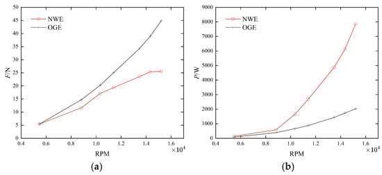
Figure 11.
Comparison of experimental results (OGE vs. NWE) [34]: (a) thrust; (b) power.
As mentioned above, the influences of NWE on rotors with different rotor sizes, rotor speeds, and rotor heights above the water surface are quite different. NWE leads to a thrust increment effect under some conditions, but there is a relative thrust loss compared to the IGE. Meanwhile, in some cases, there is a significant thrust loss compared with the OGE. There is a lack of harmonized definitions to describe these different phenomena, as indicated in Table 2. Although an increase in torque occurs under most NWE conditions, due to the lack of comparative experiments, an understanding of the thrust loss and torque increase under different conditions due to vortex rings or droplets remains controversial.
Table 2.
Results of near-water experiments conducted with rotors and ducted fans.
Subsequently, in 2024, Bai et al. [35] conducted a groundbreaking study that applied insights from gas–liquid interaction phenomena [36,37,38,39,40] observed in oxygen steelmaking converters to analyze rotor–water interface dynamics. Through a systematic analysis of water surface deformation patterns, droplet splash characteristics, and rotor aerodynamic performance, the researchers defined the NWE as possessing three distinct interaction regimes: the dimpling mode (characterized by concave surface deformation), splashing mode (marked by intense droplet generation), and penetrating mode (significant splash rebound into rotor disk), as shown in Figure 12.
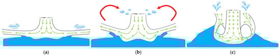
Figure 12.
Schematic of typical depression modes [35] (the green arrows show the approximate trajectory of air, the red curve shows the approximate trajectory of the droplets entering the rotor disk): (a) dimpling; (b) splashing; (c) penetrating.
The dimpling mode refers to the depression condition in which there is a slight water depression without any droplets entering the rotor disk. Compared with the OGE, the trend in thrust increment under the NWE is similar to the IGE, while this increment is slightly smaller than that of the IGE in this mode. This kind of NWE has been observed for a two-bladed rotor blade with D = 0.25 m [17].
In the splashing mode, there is a shallow depression with many upwardly directed droplets impacting the blades. A clear turning point occurs in the thrust curve, after which the thrust increment begins to decrease due to droplets; however, there is almost always a net effect of thrust increment, which means that the thrust loss due to droplets or the vortex ring is less than the thrust increment, which contributes to the high-pressure zone between the rotor blade and media boundary. This kind of NWE has been observed for a D = 0.56 m two-bladed rotor blade [17].
In the penetrating mode, there is an increase in the upward rebound splashing and a deep depression shape. A large number of splashes enter the rotor disk, instead of droplets. Thrust loss always exists, which decreases with the rotor away from the water surface. This kind of NWE has been observed for a D = 0.13 m three-bladed rotor blade [29] and a D = 0.07 m ducted fan [35]. Given that the rotor is enveloped by a significant amount of splashes, akin to the continuous cross-media progress, the variations in the medium environment should be taken into account in this mode.
The discovery of the water surface depression modes significantly contributes to a deeper understanding of the NWE. The aerodynamic characteristics of rotors operating above water surfaces are predominantly governed by the intricate interactions between the rotor wake and the water surface, as well as the dynamics of droplet–blade interactions. As previously discussed, the NWE is fundamentally distinct from the IGE. The current knowledge regarding these complex phenomena is still incomplete, necessitating additional experimental investigations on rotors of varying scales to achieve a thorough understanding of their governing mechanisms.
Furthermore, considering the experimental results using a ducted fan obtained by Huo [32], it can be assumed that the thrust loss under the NWE may be related to a high blade solidity or downwash velocity. It is worth noting that, while both ducted fans and rotors induce mixed air–water flows and present a significant increase in blade load, the power increase in ducted fans is much greater than that of rotors, which may be related to the presence of a duct. The duct has the effect of constricting the flow tube, resulting in a greater downwash velocity compared to a rotor with the same blade size, leading to more droplets tearing and bouncing off the water surface, while the low-pressure zone at the duct lip section causes a large amount of the water–air mixture to be sucked into the duct. These analyses provide important guidance for the design of cross-media vehicles: although ducted fans have the advantage of compact structure and reduction in tip energy loss, the aerodynamic performance of ducted fans deteriorates sharply near water. Therefore, for cross–media vehicles, rotors are a better choice to provide vertical take-off and landing capability, when compared to ducted fans.
3. Numerical Simulations
Computational Fluid Dynamics (CFD) is an effective method to quickly obtain the aerodynamic performance and flow mechanism of cross-media vehicles. To date, many studies of cross-media vehicles based on CFD have primarily focused on investigating the hydrodynamic characterization of high-speed cross-media processes, with a particular emphasis on the evolution of cavitation [41,42,43]. Regrettably, there are few numerical investigations on the aerodynamic characteristics of rotors and ducted fans hovering near a water surface. While it has become increasingly evident that the NWE and IGE exhibit fundamental differences, the precise mechanisms responsible for thrust loss continue to be a subject of considerable debate in this field.
In 2020, Mi et al. [44] analyzed the aerodynamic performances of a ducted fan considering the IGE, the NWE over static water, and the NWE over a dynamic water surface using the sliding mesh technique and the volume of fluid (VOF) model. The results demonstrated that both the IGE and NWE cause the total thrust of the ducted fan to decrease with decreasing height between the boundary and the system; however, the degree of the NWE was weaker than IGE, as illustrated in Figure 13a. This phenomenon was attributed to weakening of the vortex ring state due to deformation of the static water surface, which is impacted by the high-speed jet flow from the duct, thus creating a water surface depression, as illustrated in Figure 13b. In contrast, under dynamic wave conditions, the thrust and torque exhibit periodic variations in response to the oscillatory motion of the waves.
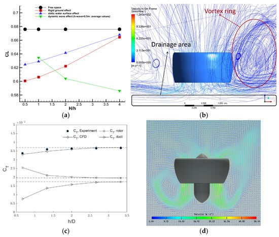
Figure 13.
Comparison of experimental results (OGE vs. NWE): (a) thrust characteristic of D = 1.3 m ducted fan under OGE, IGE, and NWE states [44]; (b) spatial streamlines under NWE state [44]; (c) thrust characteristic of D = 0.15 m ducted fan [45]; (d) diagram of velocity vector [45].
Subsequently, in 2023, Zhao et al. [45] carried out numerical simulation of a ducted fan hovering near a water surface based on the LBM (Lattice Boltzmann Method), as well as verifying the effect of the vortex ring on thrust loss, as shown in Figure 13d. The simulation results at low rotor speeds were in good agreement with experiments, as shown in Figure 12c.
The specific influence mechanism is that, upon interaction with the water surface, the wake generated by the ducted fan rebounded laterally along the sides of the duct. This intermittent entrainment of the jet flow by the rotor led to the development of a closed, ring-shaped airflow structure, commonly referred to as the vortex ring state. It is worth noting that the thrust generated by the ducted fan can be divided into two components: rotor thrust and duct thrust. As such, the effects on ducts and rotors should be discussed separately. The high-pressure region under the rotor induces airflow deceleration around the duct, weakening the duct’s thrust performance due to suction spike loss near the leading edge. As the rotor height above the water surface increases, the vortex ring gradually shifts downward and weakens. Notably, as the ducted fan approaches the water surface, the thrust generated by the rotor increases while the thrust produced by the duct decreases, ultimately resulting in a net reduction in the total thrust of the ducted fan system, as shown in Figure 13c.
However, this study [45] only conducted numerical simulations at low rotor speeds, which showed that the thrust loss and the increase in torque are caused by the vortex ring. In fact, considering the near-water experiments discussed in Section 2, ducted fans are highly susceptible to transitioning into a penetrating mode. The vigorous interaction between the ducted fan’s downwash and the water surface results in substantial spray ingress into the duct, highlighting the need to account for medium variations and droplet dynamics. Nevertheless, existing studies have predominantly relied on the VOF method for simulations, which lacks the capability to accurately capture the violent fragmentation of the water surface and the subsequent spray dispersion phenomena. Consequently, the results obtained from numerical simulations may exhibit substantial discrepancies when compared to actual experimental observations, as shown in Figure 14.
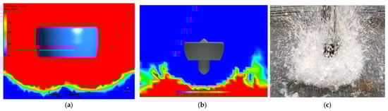
Figure 14.
Water surface shape: (a) simulation result for D = 1.3 m ducted fan [44]; (b) simulation result for 0.15 m diameter ducted fan [45]; (c) experimental result for D = 0.07 m ducted fan [35].
Later in 2023, Yang et al. [46] carried out numerical simulation of a D = 12 m Caradonna–Tung rotor blade under IGE, new, and dynamic wave conditions using STAR-CCM+ with the VOF model. The non-dimensional height z/R for the IGE and NWE conditions was set as 0.5. The numerical simulation results indicated that the degree of the NWE was weaker than that of the ground, as shown in Table 3. Furthermore, the high-pressure region below the rotor disk was significantly weaker under NWE than IGE conditions, due to the damping effect of the soft water surface that consumes some of the energy as the downwash flows impact the water surface. Waves increase rotor thrust and the thrust increment is positively related to the wave amplitude, leading to the same conclusion regarding the wave influence as Mi [44]. Considering that the rotor size used in this simulation was 12 m, which is likely to exhibit the dimpling mode under the specified conditions, the results of this simulation provide valuable reference insights. In this case, the near-water effect can be considered as a “weak ground effect.”
Table 3.
Thrust and thrust coefficients obtained in [46].
In 2023, Wang et al. [47] carried out numerical simulations of a D = 1.16 m three-bladed tilt-rotor cross-media vehicle under OGE, IGE, and NWE conditions based on Fluent using the VOF model. The non-dimensional heights z/R for the water hovering condition were set in a range from 0.4 to 2.2. The simulation results showed that as the rotor operates closer to the rigid ground or water surface, the IGE induces a significant thrust enhancement, whereas the thrust improvement due to the NWE is comparatively smaller, with torque following the same trend (see Figure 15a,b). It is noteworthy that these findings diverge significantly from the results reported by Bai [17] and Xu [29]. Due to the absence of experimental validation for near-water conditions in this study, the credibility of the simulation outcomes necessitates further investigation. Nevertheless, the flow characteristics captured in the simulations offer valuable perspectives for investigating the underlying factors responsible for thrust loss under NWE conditions.
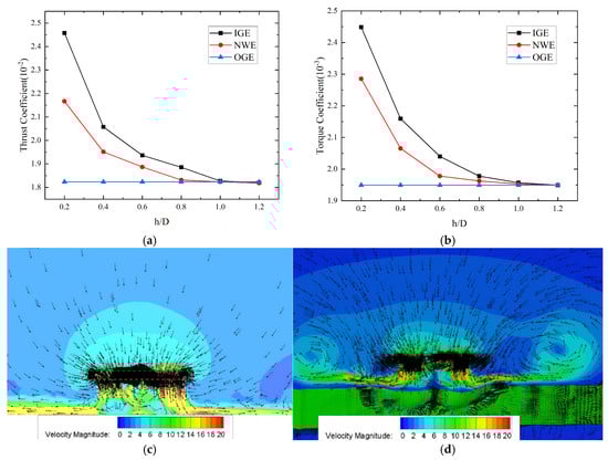
Figure 15.
Velocity contour map and aerodynamic characteristics [47]: (a) thrust coefficient at different rotor heights; (b) torque coefficient at different rotor heights; (c) the velocity magnitude field under the IGE state; (d) the velocity magnitude field under the NWE state.
The velocity magnitude field under the IGE state can be seen in Figure 15c: after the downwash reaches the ground in the axial direction, it turns in the radial direction and develops into the downstream. The ground jet flow is almost parallel to the ground. However, under the NWE state, as shown in Figure 15d, the downwash of the rotor hits the water surface and creates a depression. Due to the presence of the water surface depression, the water surface jet flow develops to the downstream in a different way. The jet flow is deflected by water surface depression, causing the rotor to enter the vortex ring state which results in aerodynamic penalties. Furthermore, rotors operating in close proximity to the water surface generate small, yet deep, depressions, whereas those positioned farther away produce larger, shallower depressions. These water surface depressions effectively alter the actual distance between the rotor and the water surface, thereby reducing the influence of the high-pressure zone on the vehicle.
In addition, Wang [47] mentioned the phenomenon that the rotor downwash drives some droplets into the rotor disk, thus increasing the load on the rotor blades. Although the effects of droplets on the aerodynamic performance of the rotor were not further analyzed and verified, the relationship between the soft water surface and flow field structures such as vortex rings obtained in this study is important for understanding the aerodynamic characteristics of near-water rotors or ducted fans.
However, while numerical simulations of both ducted fans and rotors operating near the water surface have demonstrated that vortex rings contribute to thrust loss relative to ground effects, the formation of these vortex rings does not necessarily occur due to the proximity of the rotor to the water. Their emergence is contingent upon specific critical conditions, which are intrinsically linked to the intensity of the interaction between the rotor wake and the water surface. In 2024, Bai et al. [35] performed Particle Image Velocimetry (PIV) measurements on a rotor with D = 0.25 m, in order to study its underlying flow mechanisms. A key finding of this study is that, at a relatively low rotor speed (approximately 4360 r/min), the rotor does not enter the vortex ring state regardless of its distance from the water surface. While the depression and liquid crown deflect and elevate the rotor wake, the water surface jet primarily flows around the liquid crown without ascending to form a vortex ring, as seen in Figure 16. The blue region in Figure 16 indicates an almost stationary flow region, closely resembling the rotor wake structure observed under IGE conditions in Figure 15c, in contrast to the structure under NWE conditions, as shown in Figure 15d. The rotor wake flows radially downstream, as opposed to flowing upward and re-entering the rotor disk. Under these conditions, the rotor can be considered as operating in the dimpling mode, where thrust loss is attributed to both the increased equivalent distance between the rotor and the boundary and the absorption of energy by the soft water surface.
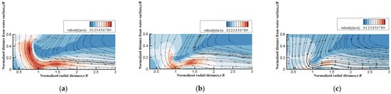
Figure 16.
Time-averaged velocity field measured via PIV at different rotor heights off the water surface [35] (arrows represent streamlines): (a) z/R = 0.5; (b) z/R = 0.2; (c) z/R = 0.1.
Furthermore, high-speed photography results have demonstrated that the rotor wake caused water surface deformation, droplet tearing, splashing, and entrainment into the rotor disk. Two distinct tearing-off mechanisms were revealed in this study: (1) interfacial instability at the water–air boundary induced by Kelvin–Helmholtz instability in water surface jet flow, as shown in Figure 17, and (2) direct droplet ejection caused by momentum transfer between the water surface and rotor downwash [48]. These mechanisms provide critical insights for comparative analysis of droplet formation patterns between large helicopters and small CMVs. Notably, despite the larger rotor dimensions and higher downwash velocities characteristic of conventional helicopters, CMVs typically operate at significantly reduced altitudes above water surfaces. This operational proximity, coupled with the enhanced momentum interaction between rotors and the water interface at equivalent dimensionless rotor heights, results in the generation of more complex droplet fields during CMV operations.

Figure 17.
Droplets generated by interface instability at low rotor speeds [35]: (a) crown formation; (b) finger structure.
Later, in 2024, Zhang et al. [49] carried out numerical simulation of an R = 1.143 m Caradonna–Tung rotor blade under IGE and FSE (free-surface effect) conditions using STAR-CCM+ with the VOF model. From the perspective of the flow field, the position of the tip vortex core, induced velocity, and pressure distributions on the blade surface were thoroughly investigated. As shown in Figure 18, the rotor downwash induces a shallow depression on the water surface, and the water surface jet develops radially without any upward flow. Therefore, there is no vortex ring in these results. Despite employing a grid resolution of 2.6 × 10⁷ and implementing grid refinement near the water surface, the simulation failed to capture any droplet splashing phenomena.
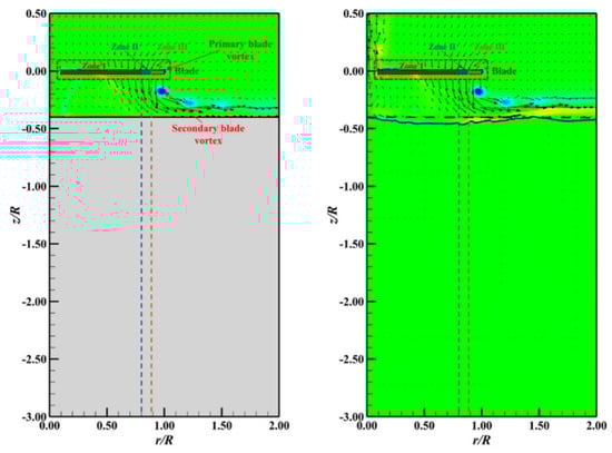
Figure 18.
Flow field through a hovering rotor under IGE (the left column in each subgraph) or FSE (the right column in each subgraph) conditions. Plots show sectional contours of dimensionless vorticity. The dark blue solid line represents the free surface at the end, while the black dashed line represents the free surface at the initial state [49].
Significantly, however, this study arrived at conclusions that starkly contradict established knowledge, as shown in Figure 19. There was a greater rotor thrust under the IGE at higher rotor heights (i.e., within the range of 0.6 < z/R < 3.0) than with the FSE, but greater rotor thrust under the FSE at lower rotor heights (i.e., within the range of z/R < 0.6). Apparently, there are no experimental data substantiating the assertion that the thrust enhancement near the water surface exceeds that of the ground effect. From the perspective of energy conservation, substantial deformation of the water surface dissipates energy from the rotor system. Moreover, the formation of water surface depressions increases the effective distance between the rotor and the boundary, thereby reducing the high-pressure region beneath the blades. Consequently, the phenomenon of the NWE being stronger than the IGE at z/R < 0.6 is inconsistent with physical principles.
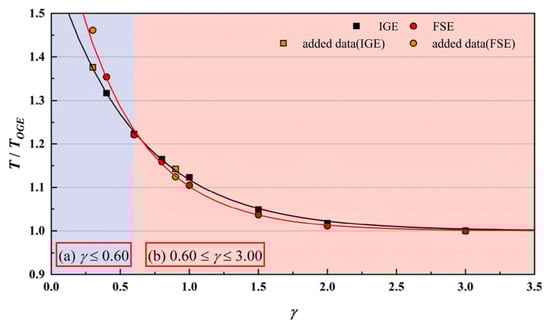
Figure 19.
Comparison of the normalized rotor thrust vs. dimensionless rotor-plane distance between the two proximity conditions. The black solid line represents the fitted curve under the IGE, while the red one represents the fitted curve under the FSE. γ represents dimensionless rotor height [49].
In summary, in recent years, researchers have conducted several studies focused on the near-water numerical simulation of rotors and ducted fans, encompassing both hovering and take-off states under static water surface conditions as well as dynamic wave environments. The primary factors responsible for thrust loss are commonly analyzed as water surface depression, vortex ring, and droplet interactions. As droplet splashing in rotor-induced mixed air–water flows is a cross-scale problem, huge amounts of meshes are required to capture the droplets as well as the impacts of droplets on the blades. However, as shown in Table 4, numerical simulations of different blades have yielded varying conclusions regarding thrust enhancement, with most results being inconsistent with experimental findings. At present, all published CFD studies lack experimental validation and, given the flow field pattern observed in near-water experiments, the reliability of numerical results for near-water rotors remains highly uncertain. Consequently, no simulation approach has yet been proven to be effective in accurately modeling mixed air–water flows—a challenge further compounded by the substantial computational grid requirements.
Table 4.
Results of near-water CFD conducted for rotors and ducted fans.
4. Aerodynamics Modeling in Cross-Media Motion Control
The stability control of a CMV is inseparable from the complete modeling of rotor near-water dynamics. To date, numerous studies have been carried out on rotor aerodynamic modeling in continuous cross-media processes, mainly focusing on medium-density variations. The variation in thruster output is always modeled as being approximately linearly correlated with fluid density changes, particularly during the transitional phase when the rotor blade operates across the air–water interface. In these cases, the effective density experienced by the rotor system undergoes a significant transition, from 1000 kg/m3 (representative of water) to 1 kg/m3 (representative of air), as the blade partially immerses in both media simultaneously.
However, most of the modeling for when the rotor is completely above the water neither takes into account changes in medium density nor ground effects but, rather, the CT (Equation (1)) measured in the OGE state is used for modeling. Therefore, there are significant differences compared to actual physical phenomena. Numerous studies focused on the aerodynamic modeling of cross-media rotorcraft have historically lacked a comprehensive understanding of the so-called “ground effect” near the water surface. Only several studies have focused on mitigating the disturbances generated by the water surface.
According to published research, Qi et al. [50] from the Air Force Engineering University were the first to notice the variation in rotor thrust induced by water surface fluctuations in 2016. Drawing on the classical IGE model based on image source theory (Equation (3)), a modified model (Equation (4)) was proposed by fitting undetermined coefficients using experimental data:
where TIGE is the rotor thrust under the IGE condition, TOGE is the rotor thrust under the OGE condition, z is the rotor’s height above the ground, and R is the radius of the rotor.
where TINPUT is the required thrust and TOUTPUT is the real thrust produced by the vehicle. Furthermore, α is a coefficient which is determined by controlling a small quadrotor to hover above the water surface at different rotor heights, as shown in Figure 20.
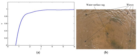
Figure 20.
Experimental results [50]: (a) thrust curve; (b) change in water surface.
This study represented the first attempt to model the NWE; however, constrained by the limited understanding of near-water phenomena at the time, the research was confined to the region above z/R = 0.7, leaving the complete cross-media process untested and unmodeled.
In 2021, Aoki et al. [14] studied the main influencing factors in the continuous cross-media process and found that no ground effect model which is suitable for water surfaces existed at the time. Later, in 2022, Aoki et al. [51] integrated the classical ground effect model rooted in mirror source theory (Equation (3)) into their aerodynamic modeling of near-water rotors. While this approach seems plausible, it is crucial to recognize that the classical ground effect model proposed by Cheeseman [28] does not consider viscosity and boundary layer effects and, thus, is only valid for z/R > 0.5 [20]. In this study, the CMV takes off from the water surface at z/R = 0 and suffers an unexpected significant “ground effect” when it is located near z/R = 0.25, which causes the trajectory obtained from the simulation to deviate significantly from the expected trajectory, as shown in Figure 21. In practice, when z/R = 0.25 is substituted into Equation (3), it becomes evident that the thrust enhancement resulting from the IGE tends to be infinite. Consequently, the classical IGE model is unsuitable for directly modeling the NWE and requires modification based on empirical data.
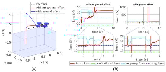
Figure 21.
Simulation results [51]: (a) trajectory tracking in the second simulation; (b) forces involved in the vehicle displacement.
In summary, over the past decade, significant research has been conducted on cross-media control algorithms and mathematical modeling for CMVs. However, a common limitation of these studies is the insufficient consideration of the profound influence of water–surface interference on the performance of cross-media rotorcraft, as well as the inadequate attention given to mixed air–water flow dynamics.
In some studies, the disturbances experienced by cross-media rotorcraft near the water surface have been mistakenly conflated with the ground effect. While extensive and well-established research, along with widely accepted models, exists for the IGE of rotors, studies on the NWE remain scarce. Due to the lack of relevant research, researchers are forced to use existing ground effect models as temporary substitutes [50,51], or to simply treat the thrust coefficient CT as a constant [14,52] without considering disturbances when developing aerodynamic models for rotors operating near the water surface. However, the accuracy of such modeling approaches requires significant improvement. Furthermore, the complex flow field generated by rotors operating near the water surface has received even less attention. From the perspective of CMV development, research on the near-water dynamic characteristics of rotors holds considerable importance for the supplementary design and refinement of control algorithms.
5. Research Challenges
5.1. Thrust Loss Mechanisms of NWE
The pronounced distinction between the NWE and IGE highlights the critical need to identify the factors responsible for thrust loss and quantify their individual contributions. Unfortunately, rotor-induced mixed air–water flows are characterized by the simultaneous presence of multiple inter-related factors, such as water surface depressions, vortex rings, and droplet dynamics, all of which collectively influence the aerodynamic performance of rotors. These factors often occur concurrently and interact in complex ways. Nevertheless, the absence of effective measurement techniques poses significant challenges in terms of quantifying and disentangling the influence of each individual factor.
The mechanism is relatively simple in the dimpling mode, with the dominant effect arising from water surface depressions. These depressions diminish the high-pressure region beneath the rotor through effectively increasing the equivalent distance, thereby reducing the thrust enhancement compared to the IGE. Under specific operating conditions, the rotor may also enter the vortex ring state, exacerbating the relative thrust loss.
In the splashing mode, the physical phenomena become highly complex, with multiple mechanisms potentially contributing to the relative thrust loss. These mechanisms include the increased equivalent distance resulting from water surface depressions, energy dissipation caused by vortex rings, and the formation of water films on the rotor blades due to droplet impacts. These factors may coexist when the rotor speed or height reaches a critical threshold. However, due to the limitations of current measurement techniques, obtaining precise parameters for individual factors remains challenging, hindering accurate modeling and analyses.
While in the penetrating mode, the interaction between the rotor wake and the water surface attains its maximum intensity, causing substantial free surface breakup. When the depression depth exceeds a critical threshold, the depression’s edge and the liquid crown significantly amplify the deflection of the water surface jet within the rotor wake. Additionally, the formation of a “water curtain” from numerous rebounding splashes and droplets can further intensify the wake’s deflection, potentially causing the blade tip to remain immersed in a highly turbulent wake. Furthermore, the variations in medium density render the near-water effects in this mode exceptionally difficult to quantify analytically.
5.2. Flow Field Measurement
Particle Image Velocimetry (PIV) is a widely used non-contact technique for flow field measurement. While PIV technology is mature for single-phase flow measurements, its application to multi-phase flows requires its integration with image processing methods to distinguish discrete phases with specific optical characteristics, as demonstrated in studies on helicopter brownout [53] and two-phase bubbly flows [54,55]. However, as evidenced by Figure 22, the primary challenge in rotor-induced mixed air–water flows lies in the highly unsteady nature of the formation and evolution of droplets and splashes. The significant and uncontrollable variations in droplet brightness and particle size across different locations at the same instant pose considerable difficulties for image processing.
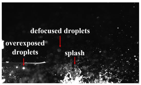
Figure 22.
Optical interference caused by droplets and splashing.
Another significant challenge is the three-dimensional characterization of rotor-induced mixed air–water flows. As illustrated in Figure 23, the edge of the depression formed by the rotor wake impacting the water surface generates a circular water splash. The intense reflection of light from the splash within the laser sheet is so strong that it causes reflected light from splashes outside the laser sheet to also enter the high-speed camera, thereby directly interfering with the cross-correlation calculations of the entire flow field. Furthermore, large droplets within the laser sheet are often overexposed. However, reducing the laser energy to prevent overexposure can result in insufficient scattered light from tracer particles in the rotor wake. Consequently, defocusing of droplets outside the laser sheet typically occurs, leading to significant variations in the optical parameters of droplets. Additionally, in the splashing mode, the maximum splash distance of droplets exceeds 5 m, imposing stringent requirements on the arrangement of high-speed cameras and measurement windows. Unlike the stable reflections caused by laser sheet illumination on the ground, these splashes are highly unsteady and cannot be effectively processed using conventional methods such as background subtraction, masking, or applying rhodamine dye. Instead, the flow field structure at the edge of the depression and the behavior of the blade tip vortex are the most critical aspects of the overall flow field analysis. In future research, fluorescent particles [55] could be employed as tracer particles for the rotor wake flow field, and filters may be used to eliminate the light reflected by droplets and splashes.
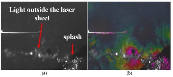
Figure 23.
The effect of splash-reflected light outside the laser sheet on the cross-correlation calculations: (a) raw image; (b) cross-correlation results.
5.3. Numerical Simulation
Rotor wake fields involve complex vortex dynamics and unsteady disturbances, presenting significant challenges for numerical methods. Various numerical models, previously developed and validated, have been employed to predict rotor aerodynamics and wake behaviors. Vortex theory-based wake models, such as the free-wake method (FWM), viscous vortex particle method (VPM), and vortex lattice method (VLM), have been employed to study rotor wake variations under IGE conditions and predict aerodynamic performance [56]. However, these models encounter considerable difficulties when applied to the more complex NWE conditions. The soft water surface introduces more intricate boundary conditions that interact with the rotor’s downwash flow, and modeling the disturbances due to droplets impacting on the blades is particularly challenging.
Computational Fluid Dynamics (CFD) methods, which solve the Navier–Stokes (N-S) equations without relying on additional wake models, are often employed to simulate transient and unsteady phenomena. However, CFD methods are prone to dissipation errors caused by grid discretization, leading to rapid decay of the rotor tip vortex intensity downstream and breakdown of the helical rotor wake structure [53]. This can distort liquid crown formation and droplet transport in rotor-induced mixed air–water flows. Additionally, rapid computational methods, such as the actuator disk model [57], offer rapid analyses but fail to capture the aerodynamic disturbances caused by droplets interacting with rotor blades or the flow characteristics of droplets and water films on the blades. It is also important to note that a reliable model for the effect of water surface dimples on thrust loss is still lacking.
In addition to the simulation of rotor wake, the simulation of multi-phase flows is also a great challenge. Over the past three decades, several approaches have been developed for the computational study of realistic multi-phase flows [58].
However, in rotor-induced mixed air–water flows, rotors generate a rapidly converging wake that exhibits significant interactions with both air and water upon contact with the water surface. In addition to simulating the rotor wake, the substantial deformation of the free surface and the processes of primary and secondary droplet breakup are also critical areas of focus. Primary breakup involves the formation of large droplets due to interface instability and momentum exchange, while secondary breakup refers to the generation of smaller droplets caused by aerodynamic forces, among other factors. Traditional CFD methods based on finite volume methods (FVMs) struggle to accurately capture the rapid fluctuations at the dynamic air–water interface. Furthermore, the high specific surface area of splashing droplets challenges the validity of the continuity assumption at sub-millimeter scales in two-phase flows, thereby undermining the reliability of methods based on directly solving the Navier–Stokes (N-S) equations for such flows [45].
To address these multi-phase challenges, the Volume of Fluid (VOF) method is commonly used for numerical simulations. In the dimpling mode, where large quantities of droplets do not enter the rotor disk to impact the blades, the VOF-based CFD approach is considered sufficiently reliable for analysis of the effects of the water surface depression on aerodynamic characteristics. However, in the splashing and penetrating modes, this method proves to be highly limited for realistic flow simulations involving large deformations and topological changes. In contrast to traditional methods, some meshless methods, such as Smoothed-Particle Hydrodynamics (SPH) [59,60], are worth testing in the considered context.
6. Future Perspectives
Despite the many challenges relating to flow field measurements and numerical simulations, having gained a fundamental understanding of the near-water effect of rotors, applied research can be carried out in the following fields to promote the development of cross-media vehicles.
6.1. Near-Water Effect of Multi-Rotor CMVs
Most existing studies on the NWE have focused on single rotors. However, cross-media rotorcrafts often present cases where multiple rotors operate in close proximity to the water surface simultaneously during the cross-media process. Consequently, the impact of the NWE on multi-rotor systems warrants significant attention, in order to identify and mitigate potential risks.
In the dimpling mode, the interactions between droplets and the rotor can be neglected. However, a phenomenon commonly observed in tilt-rotor vehicles may occur; namely, the fountain effect. In this scenario, the wakes of each rotor propagate radially after impacting the water surface, converging at the midpoint and subsequently flowing upward in a fountain-like manner. This phenomenon can cause the rotors to enter the vortex ring state earlier than in the single-rotor case, resulting in increased induced velocity and greater thrust loss, as illustrated in Figure 24.
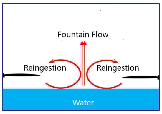
Figure 24.
Schematic of potential fountain effect as part of near-water effect for multi-rotor CMVs.
Furthermore, the interaction of the rotor downwash with the water surface generates the depression and liquid crown, which can deflect the jet flow between the two rotors. This may result in more intricate fountain flows or an earlier onset of the vortex ring state. In addition to the dimensionless height, rotor speed, and blade size—key factors for a single rotor—the spacing s between the two rotors is also a crucial parameter, as shown in Figure 25. It directly influences the wake flow structure of each rotor, and the varying configurations of merged or independent water depressions at different spacings can significantly affect the wake development between the rotors, potentially amplifying the fountain effect. The influence of this spacing will directly impact the CMV’s layout design. Consequently, it is imperative to develop an initial understanding of the NWE for multi-rotor CMVs as soon as possible, in order to enable such cross-media rotorcraft to achieve optimal aerodynamic efficiency.
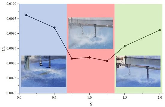
Figure 25.
Mixed air–water flows induced by multi-rotor system and thrust characteristics at n = 6600 r/min and z/R = 0.5.
6.2. Layout Design of Cross-Media Vehicles Considering the Near-Water Effect
Existing CMV designs typically consider meeting the performance requirement in each medium before optimization for balanced water–air performance. For rotors providing vertical take-off and landing lift, the results of ground tests are usually utilized to assess whether their performance is adequate to support the vehicle out of the water. However, any layout of vehicles will carry some water with it in the water exit process, resulting in an increase in its total mass when compared to operating under OGE conditions, while the NWE will also result in thrust loss for the rotors. In addition, the spacing of neighboring rotors also directly affects the near-water effect of multi-rotor CMVs, potentially resulting in further thrust loss. Therefore, placing the rotors at different maximum heights above the water as an initial position, as well as rationally designing the spacing between neighboring rotors, should be considered in the layout design, which may bring the benefit of optimizing utilization of the near-water effect to obtain additional thrust under certain conditions.
Considering the NWE of multi-rotor systems, as mentioned in Section 6.1, variations in rotor spacing can significantly influence the aerodynamic performance of a CMV. Consequently, during their design, careful optimization of their operational speed, rotor height above the water surface, and rotor spacing can be employed to achieve maximum aerodynamic efficiency. This approach not only mitigates the structural damage to blades induced by droplet impacts but also reduces energy consumption during cross-media progress, ultimately enhancing the range and endurance of the CMV.
6.3. Rotor Blade Design for Cross-Media Rotorcrafts
Considering the technical difficulties posed by tilt-rotor vehicles, the rotors of current cross-media rotorcrafts are mainly used for vertical take-offs and landings on the water surface, instead of cruising. As mentioned in Section 6.2, the fuselage always carries a large amount of additional mass in the water exit process, and the cross-media vehicle needs to hover briefly to unload water from its fuselage after exiting the water. Therefore, the rotor needs to reach its optimal performance point in mixed air–water flows instead of operating under OGE conditions; however, existing rotors are not designed to take into account the effects of mixed air–water flows, whether in terms of the water film on the blades or the air–water mixture environment.
At present, rotor designers basically adopt an approach based on traditional blade element momentum (BEM) theory; as such, the interactions between droplets and the rotor blade in a mixed water–air flow field are not taken into consideration. It is worth noting that rotor blades with different airfoil and blade tip types have different aerodynamic characteristics under rotor-induced mixed air–water flows, as shown in Section 2, Table 1. However, the specific impact mechanisms and directions for optimization of the blade design are still unclear. Due to the limitations of available measurement techniques, only the water film remaining on the rotor blade after the rotor stops can be observed to speculate that the droplets have complex flow characteristics on the rotor blade, as shown in Figure 26. It is worth conducting experimental explorations to obtain blade characteristics with better aerodynamic properties in mixed water–air flow fields, which can serve as a reference for future blade design.
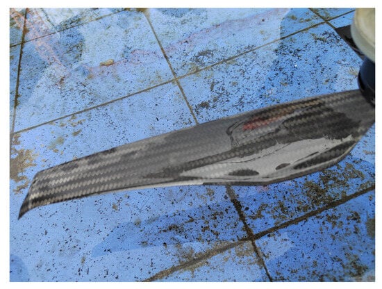
Figure 26.
The water film remaining on the blade.
Notably, rotor blade designs must also account for the depression modes. In the dimpling mode, existing blades demonstrate satisfactory performance. Meanwhile, in the splashing mode, it is essential to consider the effects of droplet impacts and water film formation on the blades and, in the penetrating mode, the design must incorporate variations in medium density and shifts in the optimal rotational speed range. A comprehensive understanding of the NWE will significantly contribute to the future development of rotor blades tailored for use in cross-media rotorcrafts.
6.4. Scale Effect
For blades of different sizes and rotational speeds, the IGE is predominantly governed by the dimensionless rotor height z/R, and its behavior is largely consistent with the Cheeseman model. In contrast, the NWE is influenced by multiple interdependent factors, leading to more intricate dynamics. When considering the interactions between droplets and the rotor, the degree of interaction between the rotor wake and the water surface differs with the blade scale, rotor speed, and rotor height, resulting in distinct depression modes. At present, there is no universally accepted dimensionless number which rules the NWE.
Furthermore, no experimental results for blades with diameters larger than 0.56 m have been presented. The authors hypothesize that, with larger blades, there may be more intense droplet splashing and thrust loss; however, this trend is not expected to continue indefinitely. Beyond a certain critical blade scale, the actual distance between the rotor and the water surface at the same dimensionless rotor height becomes substantial, diminishing the interactions between the rotor wake, tip vortices, and the water surface. Consequently, the near-water effect under such conditions would more closely approximate the ground effect, similar to the case for a helicopter.
7. Conclusions
The preceding content provided a systematic and comprehensive review and analysis of aerodynamic models, computational methods, and experimental measurements available in the public domain, as well as their relationships, focusing on the current state-of-the-art research regarding the near-water effect of rotors on CMVs. The primary objective was to present the evolving understanding of the aerodynamic penalties associated with near-water rotors and ducted fans, which are inherently encountered during cross-media transitions.
In summary, this review was organized into five sections, providing a comprehensive overview of recent research advances regarding the near-water effect of rotors. Section 2 examined the latest experimental insights with respect to the NWE, with a particular emphasis on the potential risks posed by droplets. Section 3 reviewed recent CFD research on near-water rotors and ducted fans, highlighting the gaps between the obtained simulation results and actual physical phenomena. Section 4 explored the aerodynamic modeling of near-water rotors in cross-media control scenarios, addressing the misunderstandings that arise when ground effect principles are inappropriately applied to water surface conditions. Section 5 outlined the key challenges relating to the advancement of research on the near-water effect, including the analysis of aerodynamic loss mechanisms, flow field measurement techniques, and numerical simulation methodologies. Finally, Section 6 presented the authors’ perspectives on the potentially usable applications of the NWE in the development of CMVs, as well as the critical research directions regarding the impact of the near-water effect on multi-rotor CMVs, which warrant immediate attention. We summarize some of the key findings of the study as follows:
- (1)
- During near-water experiments using rotors, distinctly different phenomena and patterns were observed across various tested blades. Compared to OGE conditions, a thrust increase sometimes occurred while, at other times, the thrust loss was substantial, with analogous trends observed in torque characteristics. Consequently, the near-water effect should be analyzed in terms of the depression modes arising from the interaction between the rotor wake and the water surface. These modes can be classified into three categories: dimpling, splashing, and penetrating. The identification of these depression modes demonstrates that the near-water effect of ducted fans and rotors is not an isolated phenomenon but, rather, manifests as distinct operational modes.
- (2)
- In the dimpling mode, the near-water effect is analogous to what is often interpreted as a “weak ground effect”, where the soft water surface absorbs energy or the increased equivalent distance to the boundary results in a small relative thrust loss compared with IGE conditions. The thrust increment trend mirrors that of the IGE, increasing as the rotor height decreases. In the splashing mode, the formation of liquid crowns and the splashing of droplets introduce nonlinear thrust increment characteristics to the near-water effect. Specifically, the thrust increment initially rises as the height decreases but, after reaching a critical threshold, declines with further reductions in height. This notable thrust loss is likely attributable to vortex rings and droplet interactions. Finally, in the penetrating mode, thrust loss occurs even at relatively large distances from the water surface compared to OGE conditions, and this loss intensifies as the height decreases. Given that the rotor becomes enveloped by water spray, variations in medium density must be accounted for when analyzing situations characterized by this penetrating mode.
- (3)
- The air–water mixed flow field induced by rotor directly affects the cross-media control performance. The use of simplified models, such as constant thrust coefficient models or ground effect models, leads to significant discrepancies between simulation results and the actual physical phenomena. Therefore, more experiments are needed to comprehensively understand the near-water effect and support accurate aerodynamic modeling.
- (4)
- Due to a lack of recognition of the potential impacts of water surface breakup and droplet splashing, existing CFD studies have commonly used the VOF method for numerical simulations. However, this method has limited capability in simulating violent water surface breakup and droplet splashing phenomena. Thus, although the existing literature has explored some flow mechanisms of the NWE using CFD, the reliability of these simulations still requires extensive experimental validation.
- (5)
- In addition to numerical simulations, flow field measurements also present considerable challenges. In air–water mixed flows, the size of droplets far exceeds that of tracer particles, and the reflected light from droplets and splashes is much stronger than the scattered light from tracer particles. Therefore, advanced optical measurement techniques—such as laser-induced fluorescence—should be explored to mitigate the overexposure caused by droplets.
- (6)
- The near-water effect on multi-rotor CMVs is critically important for the design of cross-media rotorcraft. Through optimizing the spacing between rotors, it is possible to maximize the beneficial aspects of the near-water effect under specific conditions while minimizing thrust loss, increases in power consumption, and structural damage to rotor blades caused by droplet impacts.
To date, there have been few studies on the near-water effect of rotors, and its underlying mechanisms are not yet fully understood. This review aims to draw attention to the near-water effect’s significant impacts on aerodynamic performance, as the rotors on cross-media rotorcraft inevitably operate in close proximity to the water surface. A combined approach involving theoretical analysis, numerical simulation, and experimental methods is essential to address the complexities of rotor-induced mixed air–water flows. A comprehensive understanding of both the advantages and disadvantages of the near-water effect is expected to significantly benefit the design of control algorithms, vehicle layouts, and rotor blades for cross-media vehicles.
Author Contributions
Conceptualization, X.B. and M.L.; methodology, W.W. and X.W.; investigation, X.B. and Q.Z.; data curation, Y.W.; funding acquisition, D.Z. and W.W. All authors have read and agreed to the published version of the manuscript.
Funding
This research was funded by the Key Laboratory of Cross-Domain Flight Interdisciplinary Technology, grant number 2023-ZY0302.
Data Availability Statement
The data are unavailable due to privacy or ethical restrictions.
Acknowledgments
The authors thank Zecheng Lin, Fukui Gao, Jinlong Ju, and Zhe Zhang for helpful discussions.
Conflicts of Interest
The authors declare no conflicts of interest.
Abbreviations
The following abbreviations are used in this manuscript:
| CMV | Cross-media vehicle |
| OGE | Out-ground effect |
| IGE | In-ground effect |
| NWE | Near-water effect |
| IWE | In-water effect |
| CFD | Computational Fluid Dynamics |
| SPH | Smoothed-Particle Hydrodynamics |
| VOF | Volume of fluid |
| PIV | Particle Image Velocimetry |
| FWM | Free-Wake Method |
| VPM | Vortex Particle Method |
| VLM | Vortex Lattice Method |
| BEM | Blade Element Momentum Theory |
| FSE | Free surface effect |
| CT | Thrust coefficient |
| R | Blade radius (m) |
| D | Blade radius (m) |
| ρ | Density (kg/m3) |
| z, h | Rotor height above ground or water surface (m) |
| γ | Dimensionless rotor height |
| T | Rotor thrust (N) |
| ω | Angular velocity (rad/s) |
| RPM | Current rotor speed (r/min) |
| RPMa | Expected rotor speed when fully in air (r/min) |
| RPMw | Expected rotor speed when fully in water (r/min) |
| s | Spacing between blade tips in multi-rotor system (m) |
| n | Rotor speed (r/min) |
References
- Zeng, Z.; Lyu, C.; Bi, Y.; Jin, Y.; Lu, D.; Lian, L. Review of hybrid aerial underwater vehicle: Cross-domain mobility and transitions control. Ocean Eng. 2022, 248, 110840. [Google Scholar] [CrossRef]
- Ma, Z.; Chen, D.; Li, G.; Jing, X.; Xiao, S. Configuration Design and Trans-Media Control Status of the Hybrid Aerial Underwater Vehicles. Appl. Sci. 2022, 12, 765. [Google Scholar] [CrossRef]
- Tan, Y.H.; Chen, B.M. Survey on the Development of Aerial-Aquatic Hybrid Vehicles. Unmanned Syst. 2021, 9, 263–282. [Google Scholar] [CrossRef]
- Maia, M.M.; Soni, P.; Diez, F.J. Demonstration of an Aerial and Submersible Vehicle Capable of Flight and Underwater Navigation with Seamless Air-Water Transition. arXiv 2015, arXiv:1507.01932. [Google Scholar]
- Li, L.; Wang, S.; Zhang, Y.; Song, S.; Wang, C.; Tan, S.; Zhao, W.; Wang, G.; Sun, W.; Yang, F.; et al. Aerial-aquatic robots capable of crossing the air-water boundary and hitchhiking on surfaces. Sci. Robot. 2022, 7, eabm6695. [Google Scholar] [CrossRef] [PubMed]
- Rockenbauer, F.M.; Jeger, S.L.; Beltran, L.; Berger, M.A.; Harms, M.; Kaufmann, N.; Rauch, M.; Reinders, M.; Lawrance, N.; Stastny, T.; et al. Dipper: A Dynamically Transitioning Aerial-Aquatic Unmanned Vehicle. In Proceedings of the Conference on Robotics—Science and Systems, Virtually, 12–16 July 2021. [Google Scholar]
- Stewart, W.; Weisler, W.; MacLeod, M.; Powers, T.; Defreitas, A.; Gritter, R.; Anderson, M.; Peters, K.; Gopalarathnam, A.; Bryant, M. Design and demonstration of a seabird-inspired fixed-wing hybrid UAV-UUV system. Bioinspiration Biomim. 2018, 13, 056013. [Google Scholar] [CrossRef]
- Horn, A.C.; Pinheiro, P.M.; Grando, R.B.; da Silva, C.B.; Neto, A.A.; Drews, P.L.J., Jr. A Novel Concept for Hybrid Unmanned Aerial Underwater Vehicles Focused on Aquatic Performance. In Proceedings of the 2020 Latin American Robotics Symposium (LARS), 2020 Brazilian Symposium on Robotics (SBR) and 2020 Workshop on Robotics in Education (WRE), Natal, Brazil, 9–13 November 2020; pp. 1–6. [Google Scholar] [CrossRef]
- Lu, D.; Xiong, C.; Zhou, H.; Lyu, C.; Hu, R.; Yu, C.; Zeng, Z.; Lian, L. Design, fabrication, and characterization of a multimodal hybrid aerial underwater vehicle. Ocean Eng. 2021, 219, 108324. [Google Scholar] [CrossRef]
- Lu, D.; Xiong, C.; Zeng, Z.; Lian, L.; IEEE. A Multimodal Aerial Underwater Vehicle with Extended Endurance and Capabilities. In Proceedings of the IEEE International Conference on Robotics and Automation (ICRA), Montreal, QC, Canada, 20–24 May 2019; pp. 4674–4680. [Google Scholar]
- Zufferey, R.; Ancel, A.O.; Farinha, A.; Siddall, R.; Armanini, S.F.; Nasr, M.; Brahmal, R.V.; Kennedy, G.; Kovac, M. Consecutive aquatic jump-gliding with water-reactive fuel. Sci. Robot. 2019, 4, eaax7330. [Google Scholar] [CrossRef]
- Mercado Ravell, D.A.; Maia, M.M.; Diez, F.J. Modeling and control of unmanned aerial/underwater vehicles using hybrid control. Control Eng. Pract. 2018, 76, 112–122. [Google Scholar] [CrossRef]
- Shi, Z.; Tan, X.; Wang, Y.; Lv, P.; Zou, Y.; Wan, X.; Lv, K.; Bingzhen, L.; Duan, H.; Li, H. Experimental Investigation of High Speed Cross-Domain Vehicles with Hydrofoil. J. Mar. Sci. Eng. 2023, 11, 152. [Google Scholar] [CrossRef]
- Aoki, V.M.; Pinheiro, P.M.; Drews, P.L.J.; Cunha, M.A.B.; Tuchtenhagen, L.G. Analysis of a Hybrid Unmanned Aerial Underwater Vehicle Considering the Environment Transition. In Proceedings of the Latin American Robotics Symposium (LARS)/Brazilian Symposium on Robotics (SBR)/Workshop of Robotics in Education (WRE), Natal, Brazil, 11–15 September 2021; pp. 90–95. [Google Scholar]
- Alzu’bi, H.; Akinsanya, O.; Kaja, N.; Mansour, I.; Rawashdeh, O. Evaluation of an aerial quadcopter power-plant for underwater operation. In Proceedings of the 2015 10th InternationaSymposium on Mechatronics and Its Applications (ISMA), Sharjah, United Arab Emirates, 8–10 December 2015; pp. 1–4. [Google Scholar]
- Sun, X.; Cao, J.; Li, Y.; Ling, Y. Efficient prediction method for the water-exit characteristics of unmanned aerial–underwater vehicles. Ocean Eng. 2024, 302, 117403. [Google Scholar] [CrossRef]
- Bai, X.-Z.; Wu, W.-H.; Lin, Z.-C.; Fan, Z.-L.; Zhang, D.-X.; Gao, F.-K. The influence factors of near water effect of rotor. Acta Aerodyn. Sin. 2023, 42, 86–99. [Google Scholar] [CrossRef]
- Matus-Vargas, A.; Rodriguez-Gomez, G.; Martinez-Carranza, J. Ground effect on rotorcraft unmanned aerial vehicles: A review. Intell. Serv. Robot. 2021, 14, 99–118. [Google Scholar] [CrossRef]
- Hayden, J.S. The effect of the ground on helicopter hovering power required. In Proceedings of the AHS 32nd Annual Forum, Washington, DC, USA, 10–12 May 1976. [Google Scholar]
- Wu, Z.; Zhang, T.; Tan, H.; Zhou, H.; Chen, W.; Xie, M. Hovering rotor aerodynamics in extreme ground effect. Chin. J. Aeronaut. 2024, 37, 204–219. [Google Scholar] [CrossRef]
- Li, D.J.; Zhou, Y.; Shi, Z.Y.; Lu, G. Autonomous Landing of Quadrotor based on Ground Effect Modelling. In Proceedings of the 34th Chinese Control Conference (CCC), Hangzhou, China, 28–30 July 2015; pp. 5647–5652. [Google Scholar]
- Lee, T.; Leishman, J.; Ramasamy, M. Fluid Dynamics of Interacting Blade Tip Vortices with a Ground Plane. J. Am. Helicopter Soc. 2010, 55, 022005. [Google Scholar] [CrossRef]
- Liu, X.A.; Ma, D.L.; Yang, M.Q.; Guo, Y.; Hu, H.D. Numerical Study on Airfoil Aerodynamics in Proximity to Wavy Water Surface for Various Amplitudes. Appl. Sci. 2021, 11, 4215. [Google Scholar] [CrossRef]
- Liang, H.; Zong, Z.; Zou, L. Nonlinear lifting theory for unsteady WIG in proximity to incident water waves. Part 1: Two-dimension. Appl. Ocean Res. 2013, 43, 99–111. [Google Scholar] [CrossRef]
- Bal, S. Free surface effects on 2-D airfoils and 3-D wings moving over water. Ocean Syst. Eng. Int. J. 2016, 6, 245–264. [Google Scholar] [CrossRef]
- Lyu, C.; Lu, D.; Xiong, C.; Hu, R.; Jin, Y.; Wang, J.; Zeng, Z.; Lian, L. Toward a gliding hybrid aerial underwater vehicle: Design, fabrication, and experiments. J. Field Robot. 2022, 39, 543–556. [Google Scholar] [CrossRef]
- Zha, J.; Thacher, E.; Kroeger, J.; Makiharju, S.A.; Mueller, M.W. Towards breaching a still water surface with a miniature unmanned aerial underwater vehicle. In Proceedings of the 2019 International Conference on Unmanned Aircraft Systems (ICUAS), Atlanta, GA, USA, 11–14 June 2019. [Google Scholar]
- Cheeseman, I.C.; Bennett, N.E. The Effect of Ground on a Helicopter Rotor in Forward Flight; Aeronautical Research Council: London, UK, 1955. [Google Scholar]
- Xu, R.; Ju, S.; Zhan, Q.; Wang, X. Design of aerial-aquatic rotor test system and experimental study of rotor performance. Flight Dyn. 2024, 42, 89–94. [Google Scholar] [CrossRef]
- Semenov, I.Y. Development of Hybrid Air-Water Rotor Transition Thrust Prediction and Control. Master’s Thesis, College Park, University of Maryland, Ann Arbor, MI, USA, 2020. [Google Scholar]
- Bi, Y.; Xu, Z.; Shen, Y.; Zeng, Z.; Lian, L. Design and Implementation of a Bone-Shaped Hybrid Aerial Underwater Vehicle. IEEE Robot. Autom. Lett. 2024, 9, 7318–7325. [Google Scholar] [CrossRef]
- Huo, Y.; Li, Y.; Feng, X. Water-surface take-off control of aquatic-aerial transdomain robot with reinforcement learning. Electr. Mach. Control 2021, 25, 139–150. [Google Scholar] [CrossRef]
- Nie, X.; Hu, Z.; Sun, H.; Gen, L. Research on vertical takeoff strategy on water surface of tiltrotor cross-domain unmanned vehicle. Ship Sci. Technol. 2022, 44, 66–71. [Google Scholar]
- Zhao, Y.; Hu, Z.; Yang, Y.; Gen, L. Research on thrust loss mechanisms of ducted propeller near water surface in vertical state. Ship Sci. Technol. 2023, 45, 67–73. [Google Scholar]
- Bai, X.-Z.; Zhang, Z.; Wu, W.-H.; Wang, X.; Zhan, Q.; Zhang, D.-X.; Yu, L. Fluid Dynamics of Interacting Rotor Wake with a Water Surface. Drones 2024, 8, 469. [Google Scholar] [CrossRef]
- Turkdogan, E.T. Fluid dynamics of gas jets impinging on surface of liquids. Chem. Eng. Sci. 1966, 21, 1133–1144. [Google Scholar] [CrossRef]
- Molloy, N.A. Impinging jet ffow in a 2-phase system-basic ffow pattern. J. Iron Steel Inst. 1970, 208, 943–950. [Google Scholar]
- Benjamin, M.A.; Jensen, R.J.; Arienti, M. Review of Atomization: Current Knowledge and Future Requirements for Propulsion Combustors. At. Sprays 2010, 20, 485–512. [Google Scholar] [CrossRef]
- Sabah, S.; Brooks, G. Splashing in Oxygen Steelmaking. ISIJ Int. 2014, 54, 836–844. [Google Scholar] [CrossRef]
- Li, M.; Li, Q.; Kuang, S.; Zou, Z. Computational Investigation of the Splashing Phenomenon Induced by the Impingement of Multiple Supersonic Jets onto a Molten Slag–Metal Bath. Ind. Eng. Chem. Res. 2016, 55, 3630–3640. [Google Scholar] [CrossRef]
- Liu, W.-T.; Zhang, A.M.; Miao, X.-H.; Ming, F.-R.; Liu, Y.-L. Investigation of hydrodynamics of water impact and tail slamming of high-speed water entry with a novel immersed boundary method. J. Fluid Mech. 2023, 958, A42. [Google Scholar] [CrossRef]
- Hong, Y.; Gong, Z.; Liu, H. The effect of atmospheric density on splash of spheres during water entry. Ocean Eng. 2023, 272, 113871. [Google Scholar] [CrossRef]
- Hong, Y.; Zhao, Z.; Gong, Z.; Liu, H. Cavity dynamics in the oblique water entry of a cylinder at constant velocity. Phys. Fluids 2022, 34, 021703. [Google Scholar] [CrossRef]
- Mi, B.G. Numerical investigation on aerodynamic performance of a ducted fan under interferences from the ground, static water and dynamic waves. Aerosp. Sci. Technol. 2020, 100, 105821. [Google Scholar] [CrossRef]
- Zhao, Y.; Geng, L.; Yang, Y.; Hu, Z. Research on Aerodynamic Characteristics of a Ducted Propeller Hovering near the Water Surface Based on a Lattice Boltzmann Method. J. Mar. Sci. Eng. 2023, 11, 1708. [Google Scholar] [CrossRef]
- Yang, F.; Zhao, G.; Chen, X.; Zhao, Q.; Cao, C. Analysis of aerodynamie charaeteristies of rotor near water surface. Flight Dyn. 2023, 41, 1–6. [Google Scholar] [CrossRef]
- Wang, J.; Chen, R.; Yu, Z.; Lu, J. Ground test and numerical investigation on aerodynamic performance of a quad tilt-rotor aircraft in ground and water effects. Ocean Eng. 2023, 289, 116169. [Google Scholar] [CrossRef]
- Hwang, H.Y.; Irons, G.A. A Water Model Study of Impinging Gas Jets on Liquid Surfaces. Metall. Mater. Trans. B-Process Metall. Mater. Process. Sci. 2012, 43, 302–315. [Google Scholar] [CrossRef]
- Zhang, M.; Duan, W.; Shao, W.; Liu, J. Comparison of rotor hovering aerodynamic performance in free-surface and ground effects using numerical methods. Phys. Fluids 2024, 36, 106107. [Google Scholar] [CrossRef]
- Qi, D.; Feng, J.; Li, Y. Dynamic model and ADRC of a novel water-air unmanned vehicle for water entry with in-ground effect. J. Vibroeng. 2016, 18, 3743–3756. [Google Scholar] [CrossRef]
- Aoki, V.M.; Evald, P.; Pinheiro, P.M.; da Silva, C.B.; Cardoso, D.D.; Cunha, M.A.B.; Drews, P.L.J. Exploring Ground Effect in a Hybrid Aerial-Aquatic Unmanned Vehicle. In Proceedings of the Latin American Robotics Symposium (LARS)/Brazilian Symposium on Robotics (SBR)/Workshop on Robotics in Education (WRE), Sao Bernardo do Campo, Brazil, 18–21 October 2022; pp. 37–42. [Google Scholar]
- Lu, D.; Guo, Y.; Xiong, C.; Zeng, Z.; Lian, L. Takeoff and Landing Control of a Hybrid Aerial Underwater Vehicle on Disturbed Water’s Surface. IEEE J. Ocean. Eng. 2022, 47, 295–311. [Google Scholar] [CrossRef]
- Sydney, A.J.; Baharani, A.K.; Leishman, J.G. Understanding Brownout using Near-Wall Dual-Phase Flow Measurements. In Proceedings of the 67th Annual Forum Proceedings of the American Helicopter Society, Virginia Beach, VA, USA, 3–5 May 2011. [Google Scholar]
- Lindken, R.; Merzkirch, W. A novel PIV technique for measurements in multiphase flows and its application to two-phase bubbly flows. Exp. Fluids 2002, 33, 814–825. [Google Scholar] [CrossRef]
- Sathe, M.J.; Thaker, I.H.; Strand, T.E.; Joshi, J.B. Advanced PIV/LIF and shadowgraphy system to visualize flow structure in two-phase bubbly flows. Chem. Eng. Sci. 2010, 65, 2431–2442. [Google Scholar] [CrossRef]
- Lee, H.; Sengupta, B.; Araghizadeh, M.S.; Myong, R.S. Review of vortex methods for rotor aerodynamics and wake dynamics. Adv. Aerodyn. 2022, 4, 36. [Google Scholar] [CrossRef]
- Khier, W. Time-Accurate versus Actuator Disk Simulations of Complete Helicopters. In High Performance Computing in Science & Engineering; Springer: Berlin/Heidelberg, Germany, 2006. [Google Scholar]
- Mohan, A.; Tomar, G. Volume of Fluid Method: A Brief Review. J. Indian Inst. Sci. 2024, 104, 229–248. [Google Scholar] [CrossRef]
- Monaghan, J.J. Smoothed particle hydrodynamics. Rep. Prog. Phys. 2005, 68, 1703–1759. [Google Scholar] [CrossRef]
- Wang, Z.-B.; Chen, R.; Wang, H.; Liao, Q.; Zhu, X.; Li, S.-Z. An overview of smoothed particle hydrodynamics for simulating multiphase flow. Appl. Math. Model. 2016, 40, 9625–9655. [Google Scholar] [CrossRef]
Disclaimer/Publisher’s Note: The statements, opinions and data contained in all publications are solely those of the individual author(s) and contributor(s) and not of MDPI and/or the editor(s). MDPI and/or the editor(s) disclaim responsibility for any injury to people or property resulting from any ideas, methods, instructions or products referred to in the content. |
© 2025 by the authors. Licensee MDPI, Basel, Switzerland. This article is an open access article distributed under the terms and conditions of the Creative Commons Attribution (CC BY) license (https://creativecommons.org/licenses/by/4.0/).