Highlights
What are the main findings?
- Synergetic integration of innovative technologies on a Blended-Wing-Body (BWB) UAV is investigated.
- The TIES method is implemented and tailored for fixed-wing UAV technology assessment based on deterministic, high-fidelity analysis.
What are the implications of the main findings?
- The combined evaluation enables systematic identification of optimal technology combinations.
- The results support informed design decisions for enhanced aerodynamic and performance efficiency in BWB UAVs.
Abstract
The current study presents a holistic technology evaluation and integration methodology for enhancing the aerodynamic efficiency and performance of a tactical, fixed-wing Blended-Wing-Body (BWB) Unmanned Aerial Vehicle (UAV) through the synergetic integration of several aerodynamic and performance-enhancing technologies. Based upon several individual technology investigations conducted in the framework of the EURRICA (Enhanced Unmanned aeRial vehicle platfoRm using integrated Innovative layout Configurations And propulsion technologies) research project for BWB UAVs, a structured Technology Identification, Evaluation, and Selection (TIES) is conducted. That is, a synergetic examination is made involving technologies from three domains: configuration layout, flow control techniques, and hybrid-electric propulsion systems. Six technology alternatives, slats, wing fences, Dielectric Barrier Discharge (DBD) plasma actuators, morphing elevons, hybrid propulsion system and a hybrid solar propulsion system, are assessed using a deterministic Multi-Attribute Decision Making (MADM) framework based on Technique for Order Preference by Similarity to Ideal Solution (TOPSIS). Evaluation metrics include stall velocity (Vs), takeoff distance (sg), gross takeoff weight (GTOW), maximum allowable GTOW, and fuel consumption reduction. Results demonstrate that certain configurations yield significant improvements in low-speed performance and endurance, while the corresponding technology assumptions and constraints are, respectively, discussed. Notably, the configuration combining slats, morphing control surfaces, fences, and hybrid propulsion achieves the highest ranking under a performance-future synergy scenario, leading to over 25% fuel savings and more than 100 kg allowable GTOW increase. These findings provide quantitative evidence for the potential of several technologies in future UAV developments, even when a novel configuration, such as BWB, is used.
1. Introduction
The Blended-Wing-Body (BWB) (Figure 1) configuration, initially proposed by Liebeck [1], is a novel and efficient configuration which integrates the fuselage and wing into a single continuous lifting surface, offering substantial aerodynamic advantages over conventional tube-and-wing designs. It was initially proposed for commercial airliner applications [1,2,3], as well as a layout for cargo transport aircraft [4]. Studies have demonstrated that the BWB configuration achieves lift-to-drag ratios approximately 30% higher than those of traditional configurations, while also offering a greater internal volume, allowing the installation of larger and heavier payloads [2,5]. The BWB configuration is also well-suited for use in UAVs [6,7].
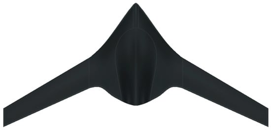
Figure 1.
The BWB configuration.
It is important to note that those advantages are accompanied by significant challenges concerning stability and control. BWBs are, by definition, tailless configurations; therefore, their design calls for a unique set of layout choices. Sweeping the wing aftwards is the most common choice, even visible to the untrained eye [1,2,6]. With swept wings, at moderate-to-high angles of attack, spanwise flow becomes dominant, promoting early flow separation and adverse phenomena such as pitch break, as highlighted by Anderson [8]. For aerial vehicles operating at Reynolds numbers between 106 and 107, which is a common range for small-scale and tactical UAVs, the spanwise flow encountered over BWBs can considerably degrade aerodynamic performance during critical flight phases such as takeoff and landing [9].
Most of those studies, concerning BWB UAVs, are case studies focusing on the sizing and design of a BWB UAV [10] or optimization studies that focus on their external layout, investigating the effects of key geometric parameters on BWB performance [11,12]. However, it is through research on and incorporation of technologies that performance specifications can really be potentially augmented. The approach of investing in State-of-the Art (SoA), and beyond SoA, disruptive technologies is a dominant trend in the field of commercial aviation research in the 21st century [13], whereas preliminary investigations show the importance of expanding this approach to fixed-wing UAVs [14]. Namely, aviation research focuses on three main categories, i.e., (1) disruptive configuration layouts, aiming in aerodynamic efficiency and performance enhancement, (2) flow control techniques that manipulate the flow to fine-tune the aerodynamic performance, either during the mission or on demand (Active Flow Control or AFC) or permanently (Passive Flow Control or PFC), and (3) novel propulsion technologies and architectures, involving a hybrid-electric approach, for reduced Specific Fuel Consumption (SFC) and emissions (noise and pollutants).
Concerning configuration layout technologies, preliminary studies indicate a significant aerodynamic performance enhancement, calculating an increase in lift-to-drag ratio of 9–12%, using an optimized winglet configuration [15]. Furthermore, morphing structures have also emerged as a potentially promising solution. Morphing refers to the ability to change the shape, mid-flight and on-demand, either on a 2D (airfoil) or on a 3D (wing) level [16]. That way, optimal performance can be achieved in on- and off-design conditions, provided that the benefits in aerodynamic efficiency overcome the weight and complexity penalty. Morphing winglets and control surfaces, capable of dynamically adapting their shape during flight, provide opportunities for optimizing aerodynamic characteristics throughout the flight envelope. Morphing winglets can potentially provide a noticeable increase in range and endurance by enhancing the lift-to-drag ratio [16] or the stability characteristics [17]. Morphing control surfaces can replace an inevitably large and complex actuation mechanism, with one broken up into smaller segments on the Leading Edge and Trailing Edge [16,18]. They offer smoother geometric transitions and reduced weight compared to conventional hinged control surfaces, leading to a reduction in the overall wing weight, providing even greater fuel savings [18]. Moreover, [19] conducts a comprehensive survey of morphing aircraft, focusing on the methods to design and model the morphing configuration, while [20] presents a thorough review of avian-inspired morphing UAVs.
Flow control and manipulation of flow characteristics are topics of great interest in fluid mechanics applications and particularly in aeronautical applications. They are mainly used to contain separation and delay stall, delay laminar-to-turbulent transition, and reduce drag. Active Flow Control Techniques (AFCTs) require some type of actuation and power input for their operation and provide dynamic means of manipulating flow separation and enhancing aerodynamic performance. The most common example is the high-lift devices on wings, i.e., trailing- and leading-edge flaps, or slats, which can be used to enhance lift production and maximum lift coefficient during the takeoff, landing, and approach segments of an aircraft mission. The use of slats has been proven to counter the pitch-break, which is one of the major disadvantages of BWB platforms [21,22]. Another innovative AFCT is Dielectric Barrier Discharge Plasma Actuators (DBD-PAs). As extensively described by Post et al. [23] and Moreau [24], they impart momentum into the boundary layer without mechanical moving parts, enabling separation control and lift enhancement. Additionally, [25] examines the control of cross-flow instabilities (CFIs) and laminar-turbulent transition on a swept wing through the plasma-based base flow modification (BFM) technique. Although DBD actuators have demonstrated considerable effectiveness in improving stall behavior and reducing drag, limitations related to actuator durability, energy consumption, and integration complexity persist, particularly for tactical UAV applications where energy efficiency is paramount. However, the aforementioned advantages, along with the potential in terms of drag reduction and stall delay (indicatively a stall angle and lift coefficient increase by approximately 2.5 degrees and 5%, respectively [26]), mean that the DBD PA is a very promising technology for UAV applications. Passive Flow Control Techniques (PFCTs) refer to structures or coatings applied over the wing and main body which are used to locally alter the flowfield, thus increasing aerodynamic efficiency or manipulating flow structures (e.g., vortices). Typical examples of PFCTs are vortex generators, riblets, wing fences, tubercles, etc. Vortex generators have been used since the 1940s to delay boundary layer separation and increase wing lift [27]. Wing fences are a more conventional and yet effective PFCT. Developed in the 50s and 60s for commercial airliner implementation at a Reynolds number range of 1 × 10⁶ to 10 × 106, it was used on swept wings to handle adverse aerodynamic phenomena [28,29] while keeping the main wing’s properties intact. Alternatively, tubercles, inspired by the leading-edge structures observed in humpback whales [30,31], generate streamwise vortices that energize the boundary layer and postpone stall onset. Furthermore, [32] presents a numerical study on tubercles’ effect on the spanwise flow distribution of a swept wing, while [33] explores the ability of a shallow surface hump to delay the transition to swept wings through a series of wing tunnel experiments.
In addition to all the above, significant research efforts have been directed toward propulsion system innovations. Hybrid-electric, distributive propulsion, and solar-assisted propulsion architectures have been investigated to reduce emissions, enhance efficiency, endurance, and increase mission flexibility. The NASA X-57 Maxwell project [34] exemplifies distributed electric propulsion concepts, demonstrating potential gains in aerodynamic efficiency and redundancy using multiple electric motors. The first aircraft to make its maiden flight on solar power solely was Sunrise I in 1974 [35]. Sunrise I revealed the potential of alternative energy sources in aviation. Moreover, NASA, during the ERAST (Environmental Research and Sensor Technology) program, examined the solar aviation capabilities of three High-Altitude Long-Endurance UAVs (Pathfinder, Centurion, and Helios) [36]. Another innovative propulsion system is the one employing hybrid-electric propulsion architectures. Hybrid electric propulsion systems (HEPS) combine the advantages of different systems, such as internal combustion (ICE) or reaction engines, electric motors, energy storage devices, power converters, etc., to create a more efficient powerplant configuration. HEPS can assure lower SFC and high efficiency [37]. Research conducted for the development of the DA36 E-star manned aircraft indicates a potential 25% decrease in fuel consumption with the use of a Series HEPS with ICE core [38]. ACARE [39] describes the potential of reducing SFC by using a combination of a series and parallel system, while also reducing emissions. Such a system works synergistically to cover the propulsion needs of an aircraft. The ability to combine two power sources effectively improves the overall efficiency of the configuration. Moreover, when discussing propulsion systems, and especially hybrid propulsion systems, a lot of effort is placed by the scientific community on the development of their sizing and optimization methods. Reference [40] presents a systematic review of the various technological alternatives used for distributive propulsion systems, while [41] analyzes the solutions used for greener aviation, including energy storage, propulsion systems, aerodynamics, etc., with the goal being to achieve green aviation through potential synergies of different technologies. Moreover, the process of the development of an analysis method for a serial hybrid electric propulsion system is presented in [42], while [43] describes a preliminary sizing method for hybrid-electric distributed-propulsion aircraft, which takes into account the powertrain architecture and associated propulsion-airframe integration effects.
From the above, it is obvious that systematic evaluation and prioritization of emerging technologies is essential for effective platform development and can provide significant advantages to the performance of a UAV. Technologies such as morphing technologies and hybrid propulsion systems have the potential to improve the aerodynamic efficiency, the performance, and the fuel consumption of a BWB UAV, as indicated by the research studies presented in the previous paragraphs. On the other hand, the integration of flow control techniques on a BWB UAV can help improve its behavior at high angles of attack and delay the appearance of pitch break. Studies like [41,44] have shown that through the synergetic application of different technologies, the performance of an aircraft can be further increased, even leading to green aviation. However, to the best of our knowledge, the previous works, especially the ones concerning UAVs, focus on exploring only one technology at a time. That is, no holistic technology assessment is available in the literature for the authors to gain insight into the synergetic evaluation of the applicable technologies and their effect on the aerodynamic efficiency and performance enhancement of fixed-wing UAVs. The advantage of this synergetic evaluation of technologies, when compared to performing isolated aerodynamic optimizations, is that it allows layout designers to either further enhance the efficiency and performance of a UAV or meet the initial design requirements that could not be satisfied. The Technology Identification, Evaluation, and Selection (TIES) methodology, developed by Mavris et al. [36], provides a structured and systematic process to select optimal technologies for complex systems, such as commercial aircraft, in the early design phases. With the implementation of TIES, the best family of alternatives for maximizing a customer-focused Overall Measure of Value (OMV) can be identified and assessed. The methodology has been validated through application to a notional 150-passenger, intra-continental transport aircraft, demonstrating its potential to guide early-stage design decisions in a rigorous and transparent manner [44,45,46].
Over the last decade, the Laboratory of Fluid Mechanics and Turbomachinery (LFMT) has investigated the integration of several technologies on BWB UAVs. In [17,47], several morphing technologies, such as morphing control surfaces, morphing twist, and morphing winglets, are assessed, and their effect on the BWB UAV reference platform is defined. Moreover, [48] performs a parametric investigation of Leading-Edge slats and computes their effect on the longitudinal stability and the performance of a BWB UAV at high angles of attack. Reference [41] explores the influence of tubercles on the aerodynamic performance of swept wings. Especially through the research activities of the EURRICA (Enhanced Unmanned aeRial vehicle platfoRm using integrated Innovative layout Configurations And propulsion technologies) [17,47,48,49] project, the goal is to evaluate the synergetic integration of such technologies (the configuration layout, the flow control, and the hybrid-electric propulsion technologies) on a novel fixed-wing BWB UAV platform. The current study presents the implementation of the TIES methodology, adjusted and tailored for a BWB UAV, to systematically assess the synergistic contributions of aerodynamic and performance-enhancing technologies toward the development of a tactical BWB UAV platform. Five technology alternatives (slats, fences, DBD plasma, morphing control surfaces, hybrid propulsion systems) that passed through the final evaluation of the EURRICA project, combined with the hybrid solar propulsion system presented in [50], are synergistically investigated and ranked in a deterministic way with the implementation of Technique for Order Preference by Similarity to Ideal Solution (TOPSIS) analysis. The effects of the integration of the selected technologies on the aerodynamic performance of the EURRICA reference platform have been defined with the use of high-fidelity Computational Fluid Dynamics (CFD) modeling. Five metrics are taken into consideration, Gross Takeoff Weight (GTOW), stall velocity (Vs), takeoff distance (sg), fuel consumption reduction, and maximum allowable GTOW (MA_GTOW). Three different weighting scenarios are implemented during TOPSIS, one giving an equal weight to all the metrics, one focusing on the performance of the BWB UAV, and one on its future enhancement. The objectives can be listed as follows:
- Implement, adjust, and investigate the applicability of TIES methodology for fixed-wing UAVs;
- Investigate the effects of the technologies and their synergetic integration on a BWB UAV, and assess their impact and synergies on the aerodynamic performance in a deterministic way, which is currently missing from the existing literature;
- Provide insights about optimal technology combinations based on the Multi-Attribute Decision-Making (MADM) method and develop a novel procedure that can be utilized both in the conceptual and in the preliminary design of a UAV.
2. Reference Platform and Individual Technology Assessment
2.1. Reference Platform and Mission Requirements
The reference platform resembles a fixed-wing, tactical BWB UAV prototype marked as RX-3, whose layout, aerodynamics, stability, and performance specifications have been defined following a comprehensive conceptual and preliminary design study [6] that complied with corresponding airworthiness regulations and was conducted at the LFMT, at the Department of Mechanical Engineering, at the Faculty of Engineering at the Aristotle University of Thessaloniki (AUTh) in Greece. The design and sizing of the UAV, along with the aerodynamic, stability, and performance analyses, were performed using well-established design methods and dedicated in-house tools that were validated against the existing literature as well as through extensive test flight campaigns. Figure 2 displays the external layout specifications, while the key geometric, mass, performance data, and operating conditions are shown in Table 1. It featured a pusher configuration with a wing sweep of 33 degrees and an AR of 8. Note that the same configuration also served as the reference platform of the EURRICA project, the framework under which many of the detailed individual technology evaluations were conducted, as described in the corresponding literature. The operating specifications of the platform resembled those of tactical UAVs, as the latter are described in [51], and they are presented with detail in [17].
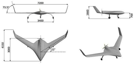
Figure 2.
External layout of the tactical BWB UAV baseline platform in millimeters (mm).

Table 1.
Baseline BWB UAV platform specifications.
2.2. EURRICA Project Technology Investigations
The EURRICA project aimed to significantly enhance the performance of the reference platform presented in Section 2.1. EURRICA explored innovative aerospace technologies grouped into three distinct categories: (1) configuration layout, (2) flow control techniques (FCT), and (3) hybrid-electric propulsion systems. Under EURRICA, a thorough screening of innovative technologies suitable for UAVs was conducted, and the selected technologies were evaluated using high-fidelity CFD and/or well-proven 0D-1D tools. Furthermore, some of the selected technologies were also synergistically applied on the reference platform, and their potential effects on the aerodynamic performance were defined.
2.2.1. Technology Screening
The technologies evaluated during EURRICA project and the ones selected for final integration on the reference platform are presented in Table 2, while a summary indicating the analysis method, the fidelity level, and the source of origin of the data of each individual technology is presented in Table 3.
Table 2.
EURRICA technology evaluation studies.
Table 3.
EURRICA technology evaluation studies solvers and origination details.
The EURRICA studies yielded that integrating fully morphing control surfaces on a BWB UAV can offer significant improvements, including a 28.2% increase in elevon effectiveness, a drag reduction up to 52.8% during positive elevon deflections, and a reduction in fuel consumption of approximately 2.5% during cruising. Despite requiring a flexible skin (adding about 1.4 kg), it was chosen due to its substantial aerodynamic and efficiency benefits, minimal complexity, and ease of integration into existing control systems [47]. Furthermore, the use of FCT, such as the wing fences, the leading-edge slats, and DBD actuators, can significantly improve performance at high angles of attack, leading to a 10–12% increase in CLmax and a delay in the angle of attack where pitch break appears up to 75% [48]. Finally, from both parallel hybrid propulsion systems selected for integration during the EURRICA project, the turboprop parallel hybrid system was finally deemed to be more promising because it offered a similar reduction in fuel consumption with the augmented one, at 22.5% compared to 25%, with a much lower increase in the GTOW of the reference platform, at 5% compared to 24%. A note must be made at this point; the structural and mass implications of the investigated technologies were taken into consideration by estimating the weight penalty of the systems that need to be added for each technology (e.g., actuators and moving mechanisms for slats and morphing control surfaces, installed weight of all the subsystems of the hybrid propulsion architectures) on a conceptual level. Those structural penalties could have been higher if potential aeroelastic effects and structural reinforcement requirements were also added for technologies such as the morphing control surfaces and slats, and structural loads and vibration characteristics of the hybrid propulsion architectures were also included in the analysis.
2.2.2. Key Assumptions and Limitations
The main assumptions for each technology can be listed as follows:
- Fully morphing control surfaces: This refers to a control surface that is fully integrated on the wing without gaps and discontinuities (Figure 3a), such as the one presented in [52]. More details about the investigation of the fully morphing control surfaces on the reference BWB UAV platform can be found in the corresponding research study [47].
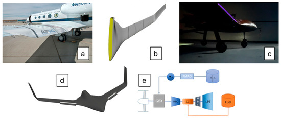 Figure 3. Indicative representations of the selected technologies. (a) Fully morphing control surfaces; (b) wing fences; (c) DBD plasma actuator; (d) leading edge slats; (e) turboprop parallel hybrid propulsion system.
 - Wing fences: Three fences are positioned at 10%, 35%, and 65% of the span in the spanwise direction [49] and cover 100% of the chord length at the suction side (Figure 3b).
- DBD plasma actuator: The plasma is positioned at the leading edge of the wing and has a span equal to 30% of the wing semispan (Figure 3c).
- Leading-edge slats: The leading-edge slat has a span equal to 45% of the semispan of the reference platform and a rotation (δs) equal to 10° (Figure 3d).
- Turboprop parallel hybrid system: In the studied propulsion configuration, it is assumed that the propulsor is driven either by a turboprop engine or a combination of both (Figure 3e). A baseline conventional configuration capable of producing 70 kW of power was assumed, based on the power needs of the reference platform [6], similarly to the already existing UAV Turbines [53] engine family.
3. Materials and Methods
3.1. TIES Methodology
The current section is a step-by-step presentation of the TIES methodology and supporting tools that are employed in this research paper. The roadmap of the methodology used in the current work is shown in Figure 4. The methodology is based on the three basic steps presented in [44] for the assessment of different technological alternatives on a given platform, which are Technology Identification (Step 1), Technology Evaluation (Step 2), and Technology Selection (Step 3).
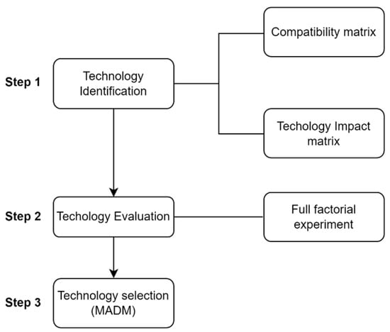
Figure 4.
Technology infusion assessment methodology.
3.1.1. Technology Investigation
The process initiates with a thorough review of the results obtained from prior feasibility assessments, particularly those concerning the baseline and preliminary concepts. These evaluations are used to identify performance deficiencies or unmet design requirements across the defined system metrics. This diagnostic insight serves as a foundation for targeted technology selection, ensuring that the integration of new technologies directly addresses the most critical limitations of existing configurations rather than proceeding in an arbitrary or speculative manner. In the current study, the technologies selected for the integration are the ones that passed the final evaluation of the EURRICA project and are presented in Table 2 and Table 3 and the solar hybrid system that was studied in [50]. The selected technology alternatives are presented in Table 4.
Table 4.
Technology alternatives under investigation.
Following this, it is crucial for the technology alternatives to be screened for compatibility using a compatibility matrix. This matrix is a symmetric, binary matrix that determines which technology combinations are physically realizable [44]. For example, some aerodynamic technologies might be incompatible with certain structural concepts. Eliminating incompatible combinations helps reduce the design space and computational load.
The next step is the construction of the Technology Impact Matrix (TIM). This maps each technology alternative to a “k-factor vector” representing its deterministic or probabilistic effect on key system metrics, including benefits and potential degradations, to accurately assess the impact of the technology alternatives. According to [44], inputs for this matrix should be derived from expert judgment, experimental data, and literature review. TIM enables the downstream evaluation of technology combinations and their collective impact on selected metrics such as fuel burn, takeoff weight, production costs, etc. In the current study, the TIM is populated based on the results of the existing investigations, mainly derived from high-fidelity analysis such as CFD and/or well-proven 0D-1D tools, thus increasing the confidence level and making TIM values deterministic. Furthermore, all the technologies were investigated on the BWB reference platform, which leaves no concerns about performance variability between different mission profiles, operational environments, or integration effects. Even though it is beyond the scope of this work, it should be noted that a probabilistic analysis could also include the mission uncertainty to allow further application of the present study results to platforms with different mission requirements. Another important note that must be made at this point is that the analysis of the EURRICA project did not stop at the investigation of ACFTs and PCFTs, individually. On the contrary, combinations of the above have also been studied with the use of high-fidelity CFD analysis, so their combined impact on the metrics is also well known and not assumed to be equal to the sum of their individual effects.
3.1.2. Technology Evaluation
Once technology alternatives and their impacts are mapped, the next step involves evaluating their combined effects on the system metrics. This step faces the challenge of combinatorial explosion: evaluating n technologies results in 2n combinations, assuming all are compatible. According to [44], for large n, exhaustive evaluation is infeasible. If computational resources are sufficient, a full-factorial probabilistic analysis can be conducted using simulations to create Cumulative Distribution Functions (CDFs) for each metric and concept. However, when resource constraints exist, a Genetic Algorithm (GA) is recommended. With the implementation of the compatibility matrix, the possible number of combinations can be reduced according to the formula presented in Equation (1).
In the current study, the analysis is deterministic, but it should be noted that a probabilistic analysis can be better for handling uncertainties and allows for future forecasts. Evaluation metrics include stall velocity (Vs), takeoff distance (sg), GTOW, maximum allowable GTOW, and fuel consumption reduction. Maximum allowable GTOW is a metric showing the allowable increase in the GTOW of the BWB UAV reference platform without exceeding specific operating parameters such as the maximum takeoff distance and maximum liftoff velocity. The metrics are selected based on guidelines in the existing aircraft design literature, as they are some of the most important parameters that dictate the design and performance of an aircraft [8,54,55]. As a first step, the CLmax, CLp, GTOW, and fuel consumption reduction parameters are calculated as a sum of the respective values of the reference and their percentage impact. The rest of the performance metrics values for each technology alternative combination are calculated with the use of an in-house tool [5,6,13], presented in Section 3.2, developed to estimate the weights and performance parameters of a UAV.
One intermediate step between Technology Evaluation and Technology Selection is the implementation of the Pugh Evaluation Matrix [56]. In the current study, the authors adopted a deterministic approach, but the following section will also include a probabilistic analysis formulation for repeatability reasons and as a reference for future studies. Each row in the matrix corresponds to a technology alternative combination, and each column represents a performance metric. Based on [44] the matrix cells are filled with metric values, ideally derived from CDFs. A critical decision here is choosing the confidence level for each metric (e.g., 80th percentile), which reflects the risk tolerance of the decision-maker. In a probabilistic setup, this confidence level acts as a filter, transforming CDFs into single representative values per metric per concept. In simpler, deterministic applications, mean or median values may be used. This stage requires careful attention to data consistency, normalization of units, and ensuring that benefit/cost metric directionality is maintained for later selection steps. Moreover, subjective judgments in selecting confidence levels can influence the results significantly. It is recommended to document these selections and, where possible, perform sensitivity analyses to understand their influence on final rankings. However, in the current study, the impact of the technology alternatives is assumed to be deterministic, so the actual metric values calculated for each alternative combination populate the Pugh matrix (Equation (2)).
Population of Pugh matrix D with m alternatives and n criteria, where is the performance metric of alternative under performance criterion .
3.1.3. Technology Selection
TOPSIS, first introduced by Hwang and Yoon [57], is an MADM method that provides a robust framework for ranking a set of alternatives based on their geometric distance to the ideal and anti-ideal solutions. It assumes that the best alternative should have the shortest Euclidean distance from the positive ideal solution (PIS) and the farthest from the negative ideal solution (NIS). MAMD allows for the selection of the most promising technologies based on trade-off and design needs. TOPSIS [58,59] is widely employed in engineering design, systems evaluation, and decision analysis due to its computational simplicity and rational basis. TOPSIS facilitates systematic and logical ranking of alternatives, making it a valuable tool for decision-makers. Its reliance on the concept of ideality makes the method intuitive and effective in scenarios involving multiple conflicting criteria.
Following the methodology established in [57] is presented below. TOPSIS is used to rank the technology alternatives based on performance metrics and the direction of preference for each metric.
The 1st step is the normalization of the Pugh matrix to eliminate unit inconsistencies and scale effects. Each element is normalized using vector normalization:
The normalized Pugh matrix is denoted as .
After the Pugh matrix is normalized, each normalized metric is multiplied by a weight representing the relative importance of the metric:
where , and the weighted normalized Pugh matrix (2nd step) is denoted as .
The weights are defined by the decision-maker or the designer based on the following:
- Stakeholder priorities;
- Mission requirements;
- Policy constraints or risk attitudes.
It is clear now that the weight selection is part of the subjective tuning of the decision making process, and Kirby’s approach encourages multiple weighting scenarios to explore robustness in the rankings of the technology alternatives.
The 3rd step is the determination of the PIS and NIS as follows:
where for benefit criteria and for cost criteria, and for benefit criteria and for cost criteria, and for benefit criteria and for cost criteria, and for benefit criteria, .
The 4th step is the computation of the Euclidean distance of each alternative from the ideal and negative-ideal solutions:
Finally, the relative closeness to the ideal solution is calculated, which allows engineers to rank technology alternatives from the best to worst. , and the closer it is to 1, the more preferable the alternative is:
Those last steps are repeated for each one of the weighting scenarios, hence different rankings will occur, allowing designers to better understand the effect of technology alternatives on the BWB UAV.
3.2. Weight and Performance Estimation Methodology
Concerning the analytical and semi-empirical presizing and performance analysis methods, an in-house tool is employed, as mentioned in Section 3.1.2, to estimate the weights and the performance parameters. The tool is based on textbook methods [8,54,55] and can be used to carry out a complete layout design and performance analysis study and has been validated on commercial airliners and UAV configurations [5,13]. Most importantly, in the framework of the current study, it is used to quickly evaluate changes occurring from the technology alternatives and assess their impact on the performance of the BWB UAV reference platform. All calculations related to the sizing and performance analysis are fully compliant with the corresponding regulations [60].
Initially, the value of the GTOW of each one of the 26 technology alternative combinations is calculated based on the penalty added for the integration of the technology alternatives. Following this, using Equations (10) and (11), Vmc (minimum control speed) and Sg (takeoff distance) are calculated. Note that W refers to the GTOW of the UAV, S is the reference area of the BWB UAV, CLp is the lift coefficient at the angle of attack where pitch break occurs, ρ is the density at sea level, CLmax is the maximum lift coefficient, and T is the thrust produced by the engine.
The impact of the technology alternatives on fuel consumption reduction is calculated based on the benefits added from the integration of the technology alternatives on the BWB UAV reference platform, whereas maximum allowable GTOW (MA_GTOW) is calculated using Equations (10) and (11) through an iterative procedure based on 2 constraints:
- Sg is to not exceed the 200 m requirement of the reference platform.
- The liftoff speed VLO is not to be greater than that of the reference platform, which is calculated as equal to 34 m/s.
Initially the GTOW is calculated from Equation (9) for the maximum value of 200 m, and then VLO is calculated for the respective GTOW as 1.1 × Vmc. If the value calculated for VLO is smaller than 34 m/s, then the MA_GTOW is equal to the GTOW calculated from Equation (10) for a 200 m ground roll distance. If not, then the MA_GTOW is calculated from Equation (9) based on the constraint of the VLO. MA_GTOW is a metric that the investigated technologies affect indirectly.
4. Results
4.1. Synergetic Evaluation of Technologies
Before the evaluation of the synergetic integration of the technology alternatives, all the necessary steps described in Section 3 are conducted. The compatibility matrix for the current study is presented in Table 5. The combination of a hybrid solar propulsion system and fences is excluded due to installation restrictions. That is, the fences disrupt the continuity of the solar panels and cast shade over a part of them, leading to an efficiency reduction. Moreover, the synergetic use of fences and DBD plasma was deemed inefficient during the EURRICA project investigations. Their combination yielded a result inferior to the one provided by the PFC alone. Furthermore, the concurrent use of slats and DBD plasma is excluded due to installation limitations, i.e., the use of plasma is limited to only on the leading edge slat surface, and the electrical interconnection of DBD plasma actuator becomes much too complex. The TIM is populated based on the results of the EURRICA project investigations (Table 6).
Table 5.
Technology alternative compatibility matrix.
Table 6.
Technology Impact Matrix.
In the current study, a full factorial analysis would lead to 64 combinations, but with the employment of the compatibility matrix (Table 5), they are reduced to 26, making the full factorial analysis feasible, leading to a 26 × 5 matrix Pugh matrix, which is then used as the input for the TOPSIS analysis.
Following this, all the metrics are calculated based on the technology impacts defined in Table 6, with the use of the methodology presented in Section 3.2. With the results of that analysis, the Pugh matrix is populated (Table 7).
Table 7.
Pugh matrix.
The evaluation considers five mission-critical criteria: GTOW, stall velocity (Vs), takeoff distance (sg), fuel consumption reduction, and maximum allowable GTOW (MA_GTOW). Initially, to quantify the influence of individual technologies, a marginal impact analysis is performed for the key mission variables (Figure 5 and Figure 6). The effect on takeoff distance (Sg) shows that the hybrid propulsion system (T6) contributes a reduction of approximately 32%, while wing fences (T3) offer a 30% reduction. In contrast, the hybrid solar propulsion system (T2) introduces an 11% increase in Sg, which is attributed to the increased GTOW. A similar trend is evident in the stall velocity (Vs) analysis: while T2 increases stall speed by over 13%, slats (T1) and wing fences (T3) slightly reduce it by 4–5%, improving low-speed handling and aerodynamic performance at high angles of attack and enabling more flexible landing configurations.
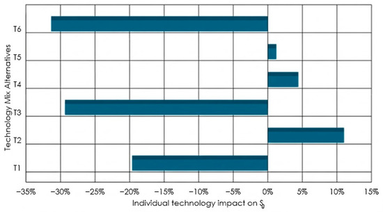
Figure 5.
Percentage impacts of the individual technologies on Sg.
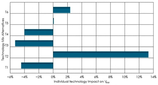
Figure 6.
Percentage impacts of the individual technologies on Vs.
Following this, TOPSIS analysis is conducted for three different weighting scenarios. One gives equal importance to all the performance metrics, one focuses mostly on the metrics concerning UAV performance, and the last one gives more importance to metrics related to the future enhancement of the UAV, as presented in Table 8. In the current study, GTOW, Vmc, Sg, and fuel consumption reduction are classified as a “cost” since the target is their minimization, whereas maximum allowable GTOW is classified as a “benefit”, as we aim to maximize it.
Table 8.
The three different weighting scenarios applied in the current study.
Table 9 summarizes the TOPSIS rankings for the top 10 performing configurations under each scenario. The results indicate a consistent presence of configurations that integrate T3 (fences) and T6 (hybrid-electric propulsion) among the top positions. Also, the TOPSIS scores for all the scenarios are presented in Figure 7, Figure 8 and Figure 9.
Table 9.
Technology alternatives mix ranking for the three different weight scenarios.
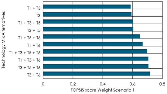
Figure 7.
Technology alternative combination effects for Weight Scenario 1.
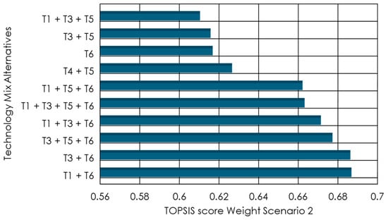
Figure 8.
Technology alternative combination effect for Weight Scenario 2.
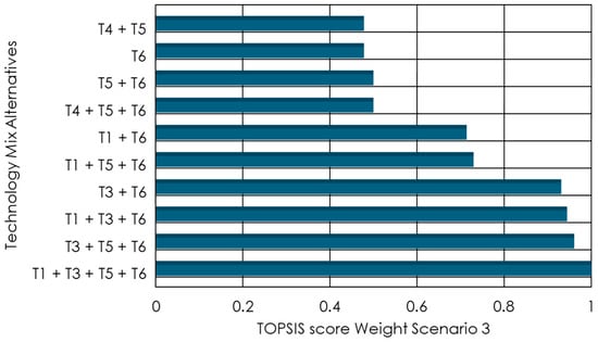
Figure 9.
Technology alternative combination effects for Weight Scenario 3.
In the baseline scenario (Scenario 1), which evenly weights all criteria, the highest-ranked configuration is the combination of fences and hybrid-electric propulsion (T3 + T6). This configuration consistently demonstrates strong performance across all metrics, particularly in reducing Sg and reducing fuel consumption compared to the baseline geometry without significantly increasing GTOW. Close contenders include the triad T3 + T5 + T6 and the morphing-augmented configuration T1 + T3 + T6. These results indicate that the synergistic effect of a hybrid propulsion system and a simple but effective PCFT, like wing fences, consistently yields balanced improvements in both aerodynamic efficiency and aircraft performance.
When shifting focus toward performance-critical requirements (Scenario 2), where GTOW, Vs, Sg, and fuel consumption reduction are prioritized (excluding MA_GTOW), a shift in optimal configurations is observed. The top performer under this weighting was T1 + T6, highlighting the positive influence of slats (T1) in augmenting the aerodynamic performance at high angles of attack during takeoff, particularly when coupled with the hybrid propulsion system. Notably, T3 + T6 and T3 + T5 + T6 are also ranked within 2% of the top configuration, reaffirming the role of wing fences in limiting the spanwise flow and delaying stall onset significantly, especially at high angles of attack.
Scenario 3, which emphasizes metrics related to the future enhancement of the EURRICA reference platform (fuel consumption reduction and MA_GTOW), shows a clear separation in performance levels, with a few configurations significantly outperforming the rest. The configuration T1 + T3 + T5 + T6 achieves a normalized TOPSIS score of 1.0. In this case, the cumulative effect of all four technologies synergistically minimizes fuel consumption reduction while also allowing a significant increase in GTOW of the BWB UAV. Such a possible increase in the GTOW can allow the expansion of the mission specifications of the UAV, either allowing for higher endurance missions by the increase in fuel capacity while also ensuring lower fuel consumption, or higher payload capacity missions, without compromising endurance compared to the baseline platform. Supporting configurations such as T3 + T5 + T6 and T1 + T3 + T6 also perform exceptionally well.
A sensitivity analysis across 126 randomly generated weighting scenarios reveals further insights into the robustness of the design candidates. The configuration T3 + T6 emerges as the most consistently high-performing option, appearing in the top three rankings in 60% of all evaluated scenarios. It is followed by T1 + T3 + T6 (50%), T3 + T5 + T6 (49%), and T1 + T3 + T5 + T6 (21%). These findings strongly suggest that wing fences (T3) and hybrid propulsion system (T6) are essential enablers for high-performance and energy-resilient UAV missions.
Ultimately, the analysis converges on several key system-level findings. First, propulsion electrification (T6) and wing fences (T3) are crucial technologies for achieving both performance and energy efficiency gains. Second, while ACFT (T1, T5) adds incremental improvements, their full benefit is unlocked when integrated alongside T3 and T6, rather than as standalone solutions. Third, the effectiveness of hybrid solar (T2) and DBD plasma (T4) is highly context-dependent and, based on current modeling, offers limited advantages compared to the mass and complexity they introduce. The presence of slats and fences in most of the top performers across the three different weight scenarios in the TOPSIS analysis can be attributed to their enhanced low-speed aerodynamics. Their combined effect can further increase the CLp and the Vmc of a BWB platform, which in turn also leads to an increase in the MA_GTOW. On the other hand, the integration of morphing control surfaces can reduce fuel consumption with a small weight penalty. Finally, the hybrid propulsion system has more available power compared to the propulsion system of the EURRICA reference platform, leading to a smaller takeoff runway, while also providing lower fuel consumption.
4.2. EURRICA Project Subscale Prototype
In the framework of the EURRICA project, a subscale prototype (Table 10) is manufactured and tested through various campaigns to investigate the effect of two of the technologies investigated during the project, a DBD plasma actuator and wing fences, on the flight behavior and the air flow over the wings of the UAV (Figure 10). Tufts are placed on the center body and the wing, and with the use of a GoPro camera, the spanwise flow in the wing is monitored. This allows us to qualitatively confirm the reduction in spanwise flow, e.g., with the use of wing fences. Both technologies are investigated separately and synergistically, leading to the conclusion that their combination does not yield the expected results regarding stall delay. This is something that confirms the decision that these two technologies are incompatible, as can be seen in the compatibility matrix of the current study. Stall tests are also conducted, and the airspeed at which stall appears is measured with an airspeed sensor. The velocities measured during the flight tests are in accordance with the ones calculated through CFD under the EURRICA project for the subscale model. Lastly, and especially concerning the DBD plasma actuator, the CFD investigations conducted in EURRICA are in accordance and were validated with the results of the experimental investigations presented in [26].
Table 10.
EURRICA subscale model specifications.
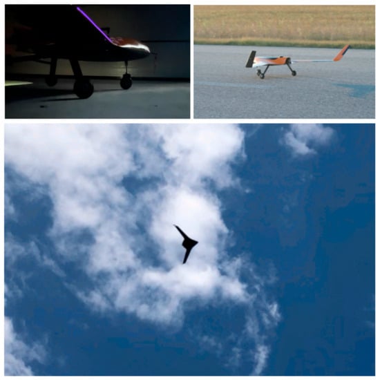
Figure 10.
Snapshots of the static tests (top left), the ground tests (top right), and the flight tests (bottom) of the EURRICA project subscale platform.
5. Discussion and Conclusions
A TIES method is employed to evaluate the effect of the synergetic evaluation of six technologies on the aerodynamic efficiency and performance enhancement of a tactical, fixed-wing BWB UAV platform. The six technology alternatives (slats, fences, DBD plasma, morphing control surfaces, and hybrid and hybrid solar propulsion system) have already been individually assessed using high-fidelity CFD modeling and 0D-1D in-house tools. In the current study, through the appropriate adjustment and application of the TIES method, a complete and holistic analysis is conducted on six performance metrics (gross takeoff weight, stall velocity, takeoff distance, fuel consumption reduction, and maximum allowable GTOW). The integrated evaluation presented in the current study confirms the transformative potential of synergetic technology combinations for BWB UAV performance enhancement. Key conclusions include the following:
- The hybrid propulsion system (T6) and wing fences (T3) consistently emerge as the most impactful technologies, contributing to up to 32% and 30% reductions in takeoff distance, respectively, and enabling substantial GTOW enhancements.
- The hybrid propulsion system (T6) and wing fences (T3) appear in the top rankings for all three weight scenarios applied during the TOPSIS analysis.
- For Scenario 3, which is related to future enhancements, morphing control surfaces (T5) are included on top-ranked technology alternatives.
- The synergetic integration of technologies yields non-linear gains. The combined application of slats, wing fences, morphing control surfaces, and hybrid propulsion (T1 + T3 + T5 + T6) achieves the best performance under all future-oriented weighting scenarios, indicating strong synergy in aerodynamic performance and energy efficiency.
- The TIES methodology, coupled with deterministic TOPSIS analysis, proved effective for ranking complex combinations of technology alternatives, without excessive computational burden.
In summary, the outcomes of this study are directly applicable to any fixed-wing UAV with a BWB configuration. Furthermore, the implementation of the presented methodology can provide useful insights for design teams to identify promising technology alternatives that can be integrated in future designs, regardless of the UAV configuration (e.g., traditional tube and wing or BWB), both during conceptual and preliminary design, thus ensuring that they can achieve mission requirements that were not satisfied during the design process, e.g., takeoff distance requirement. Further research could focus on probabilistic assessments, taking into consideration the technology readiness level (TRL) of each technology alternative. Moreover, other metrics could also be used for the TOPSIS ranking, such as cost, system complexity, and reliability. Although the authors have substantial information on these metrics, the absence of a well-established model for fixed-wing UAV applications did not allow for their inclusion in the current study. An important aspect that could be investigated in future studies is how technologies such as morphing control surfaces, slats, or hybrid propulsion mass distributions affect flap effectiveness, twist distribution, aeroelastic stability (flutter), and load paths. Furthermore, this study can be expanded to both smaller and larger fixed-wing UAVs, such as small-scale or HALE UAVs, to investigate whether the benefits of the presented technologies remain within the margins suggested in the present work.
Author Contributions
Conceptualization, S.K.; methodology, S.K. and P.P.; software, S.K.; validation, P.P. and K.Y.; formal analysis, S.K.; investigation, S.K. and P.P.; resources, S.K.; data curation, S.K.; writing—original draft preparation, S.K.; writing—review and editing, P.P. and K.Y.; visualization, S.K.; supervision, P.P.; project administration, P.P.; funding acquisition, P.P. and K.Y. All authors have read and agreed to the published version of the manuscript.
Funding
This research received no external funding.
Data Availability Statement
Data available on request due to restrictions related to the details of the baseline platform. The data presented in this study are available on request from the corresponding author.
Conflicts of Interest
The authors declare no conflicts of interest.
Abbreviations
The following abbreviations are used in this manuscript:
| AFC | Active Flow Control |
| AR | Aspect Ratio |
| AUTh | Aristotle University of Thessaloniki |
| AFCTs | Active Flow Control Techniques |
| BWB | Blended Wing Body |
| CC | Combustion Chamber |
| CDFs | Cumulative Distribution Functions |
| CFD | Computational Fluid Dynamics |
| DBD | Dielectric Barrier Discharge |
| EURRICA | Enhanced Unmanned aeRial vehicle platfoRm using integrated Innovative layout Configurations And propulsion technologies |
| ERAST | Environmental Research and Sensor Technology) |
| GA | Genetic Algorithms |
| GBX | Gearbox |
| GTOW | Gross Takeoff Weight |
| HEPS | Hybrid-Electric Propulsion Systems |
| HPC | High Pressure Compressor |
| HPT | High Pressure Turbine |
| ICE | Internal Combustion Engine |
| LFMT | Laboratory of Fluid Mechanics and Turbomachinery |
| LPT | Low Pressure Turbine |
| MADM | Multi-Attribute Decision Making |
| NASA | National Aeronautics and Space Administration |
| NIS | Negative Ideal Solution |
| OMV | Overall Measure of Value |
| PA | Plasma |
| PIS | Positive Ideal Solution |
| PMAD | Power Management and Distribution System |
| PFC | Passive Flow Control |
| PFC | Passive Flow Control Techniques |
| SoA | State of the Art |
| SFC | Specific Fuel Consumption |
| TIES | Technology Identification, Evaluation and Selection |
| TIM | Technology Impact Matrix |
| TOPSIS | Technique for Order Preference by Similarity to Ideal Solution |
| UAV | Unmanned Aerial Vehicle |
References
- Liebeck, R.H. Design of the Blended Wing Body Subsonic Transport. J. Aircr. 2004, 41, 10–25. [Google Scholar] [CrossRef]
- Qin, N.; Vavalle, A.; Le Moigne, A.; Laban, M.; Hackett, K.; Weinerfelt, P. Aerodynamic Considerations of Blended Wing Body Aircraft. Prog. Aerosp. Sci. 2004, 40, 321–343. [Google Scholar] [CrossRef]
- Bradley, M.K.; Droney, C.K. Subsonic Ultra Green Aircraft Research: Phase I Final Report; NASA Langley Research Center: Hampton, VA, USA, 2011. [Google Scholar]
- Wakayama, S. Blended-Wing-Body Optimization Problem Setup. In Proceedings of the 8th Symposium on Multidisciplinary Analysis and Optimization, Long Beach, CA, USA, 6 September 2000. [Google Scholar]
- Panagiotou, P.; Fotiadis-Karras, S.; Yakinthos, K. Conceptual Design of a Blended Wing Body MALE UAV. Aerosp. Sci. Technol. 2018, 73, 32–47. [Google Scholar] [CrossRef]
- Panagiotou, P.; Mitridis, D.; Dimopoulos, T.; Kapsalis, S.; Dimitriou, S.; Yakinthos, K. Aerodynamic Design of a Tactical Blended-Wing-Body UAV for the Aerial Delivery of Cargo and Lifesaving Supplies. In Proceedings of the AIAA Scitech 2020 Forum, Orlando, FL, USA, 5 January 2020; American Institute of Aeronautics and Astronautics Inc., AIAA: Orlando, FL, USA, 2020; Volume 1. Part F. [Google Scholar]
- Suewatanakul, S.; Porcarelli, A.; Olsson, A.; Grimler, H.; Chiche, A.; Mariani, R.; Lindbergh, G. Conceptual Design of a Hybrid Hydrogen Fuel Cell/Battery Blended-Wing-Body Unmanned Aerial Vehicle—An Overview. Aerospace 2022, 9, 275. [Google Scholar] [CrossRef]
- Anderson, J.D. Fundamentals of Aerodynamics, 5th ed.; McGraw-Hill: New York, NY, USA, 2011. [Google Scholar]
- Velázquez, O.E.; Weiss, J.; Morency, F. Preliminary Investigation on Stall Characteristics of a Regional BWB for Low Speed Approach. In Proceedings of the 35th AIAA Applied Aerodynamics Conference, Denver, CO, USA, 5–9 June 2017; American Institute of Aeronautics and Astronautics Inc., AIAA: Orlando, FL, USA, 2017. [Google Scholar]
- Lehmkuehler, K.; Wong, K.C.; Verstraete, D. Design and Test of a UAV Blended Wing Body Configuration. In Proceedings of the 28th Congress of the International Council of the Aeronautical Sciences, Brisbane, Australia, 23–28 September 2012; pp. 432–442. [Google Scholar]
- Mohammad Zadeh, P.; Sayadi, M. An Efficient Aerodynamic Shape Optimization of Blended Wing Body UAV Using Multi-Fidelity Models. Chin. J. Aeronaut. 2018, 31, 1165–1180. [Google Scholar] [CrossRef]
- Lyu, Z.; Martins, J.R.R.A. Aerodynamic Design Optimization Studies of a Blended-Wing-Body Aircraft. J. Aircr. 2014, 51, 1604–1617. [Google Scholar] [CrossRef]
- Heinemann, P.; Panagiotou, P.; Vratny, P.C.; Kaiser, S.; Hornung, M.; Yakinthos, K. Advanced Tube and Wing Aircraft for Year 2050 Timeframe. In Proceedings of the 55th AIAA Aerospace Sciences Meeting, Gravepine, TX, USA, 9–13 January 2017. [Google Scholar]
- Panagiotou, P.; Yakinthos, K. Aerodynamic Efficiency and Performance Enhancement of Fixed-Wing UAVs. Aerosp. Sci. Technol. 2019, 99, 105575. [Google Scholar] [CrossRef]
- Whitcomb, R.T. A Design Approach and Selected Wind-Tunnel Results at High Subsonic Speeds for Wing-Tip Mounted Winglets; NASA Langley Research Center: Hampton, VA, USA, 1976. [Google Scholar]
- Barbarino, S.; Bilgen, O.; Ajaj, R.M.; Friswell, M.I.; Inman, D.J. A Review of Morphing Aircraft. J. Intell. Mater. Syst. Struct. 2011, 22, 823–877. [Google Scholar] [CrossRef]
- Panagiotou, P.; Antoniou, S.; Yakinthos, K. Cant Angle Morphing Winglets Investigation for the Enhancement of the Aerodynamic, Stability and Performance Characteristics of a Tactical Blended-Wing-Body UAV. Aerosp. Sci. Technol. 2022, 123, 107467. [Google Scholar] [CrossRef]
- Burdette, D.A.; Martins, J.R.R.A. Impact of Morphing Trailing Edges on Mission Performance for the Common Research Model. J. Aircr. 2019, 56, 369–384. [Google Scholar] [CrossRef]
- Chu, L.; Li, Q.; Gu, F.; Du, X.; He, Y.; Deng, Y. Design, Modeling, and Control of Morphing Aircraft: A Review. Chin. J. Aeronaut. 2022, 35, 220–246. [Google Scholar] [CrossRef]
- Harvey, C.; Gamble, L.L.; Bolander, C.R.; Hunsaker, D.F.; Joo, J.J.; Inman, D.J. A Review of Avian-Inspired Morphing for UAV Flight Control. Prog. Aerosp. Sci. 2022, 132, 100825. [Google Scholar] [CrossRef]
- Wang, H.; Jiang, X.; Chao, Y.; Li, Q.; Li, M.; Zheng, W.; Chen, T. Effects of Leading Edge Slat on Flow Separation and Aerodynamic Performance of Wind Turbine. Energy 2019, 182, 988–998. [Google Scholar] [CrossRef]
- Li, W.; Guo, Y.; Liu, W. On the Mechanism of Acoustic Resonances from a Leading-Edge Slat. Aerosp. Sci. Technol. 2021, 113, 106711. [Google Scholar] [CrossRef]
- Post, M.L.; Corke, T.C. Separation Control Using Plasma Actuators—Stationary & Oscillating Airfoils. In Proceedings of the 42nd AIAA Aerospace Sciences Meeting and Exhibit, Reno, NV, USA, 5–8 January 2004; AIAA Meeting Paper. American Institute of Aeronautics and Astronautics Inc.: Reno, NV, USA, 2004; pp. 9432–9444. [Google Scholar]
- Moreau, E. Airflow Control by Non-Thermal Plasma Actuators. J. Phys. D Appl. Phys. 2007, 40, 605–636. [Google Scholar] [CrossRef]
- Peng, K.; Avallone, F.; Kotsonis, M. Plasma-Based Base Flow Modification on Swept-Wing Boundary Layers: Dependence on Flow Parameters. J. Fluid. Mech. 2024, 997, A13. [Google Scholar] [CrossRef]
- Kaparos, P.; Koltsakidis, S.; Panagiotou, P.; Yakinthos, K. Experimental Investigation of DBD Plasma Actuators on a BWB Aerial Vehicle Model. In Proceedings of the AIAA Aviation Forum—2018 Flow Control Conference, Atlanta, GA, USA, 25 June 2018; American Institute of Aeronautics and Astronautics Inc.: Atlanta, GA, USA, 2018. [Google Scholar]
- Bragg, M.B.; Gregorek, G.M. Experimental Study of Airfoil Performance with Vortex Generators. J. Aircr. 1987, 24, 305–309. [Google Scholar] [CrossRef]
- Bray, R.S. The Effects of Fences on the High-Speed Longitudinal Stability of a Swept-Wing Airplane; NACA Research Memorandum; NATIONAL ADVISORY COMMITTEE FOR AERONAUTICS: Washington, DC, USA, 1953. [Google Scholar]
- Cleary, J.W.; Boddy, L.E. Wind-Tunnel Investigation of a 45 Degree Sweptback Wing Having a Symmetrical Root and a Highly Cambered Tip, Including the Effects of Fences and Lateral Controls; NACA Research Memorandum; NATIONAL ADVISORY COMMITTEE FOR AERONAUTICS: Washington, DC, USA, 1953. [Google Scholar]
- Fish, F.E.; Battle, J.M. Hydrodynamic Design of the Humpback Whale Flipper. J. Morphol. 1995, 225, 51–60. [Google Scholar] [CrossRef]
- Miklosovic, D.S.; Murray, M.M.; Howle, L.E.; Fish, F.E. Leading-Edge Tubercles Delay Stall on Humpback Whale (Megaptera Novaeangliae) Flippers. Phys. Fluids 2004, 16, L39–L42. [Google Scholar] [CrossRef]
- Papadopoulos, C.; Katsiadramis, V.; Yakinthos, K. Influence of Tubercles’ Spanwise Distribution on Swept Wings for Unmanned Aerial Vehicles. Inst. Mech. Eng. Part G J. Aerosp. Eng. 2021, 235, 95–103. [Google Scholar] [CrossRef]
- Rius-Vidales, A.F.; Morais, L.; Westerbeek, S.; Casacuberta, J.; Soyler, M.; Kotsonis, M. Delay of Swept-Wing Transition Using a Surface Hump. J. Fluid. Mech. 2025, 1014, A35. [Google Scholar] [CrossRef]
- Borer, N.K.; Derlaga, J.M.; Deere, K.A.; Carter, M.B.; Viken, S.A.; Patterson, M.D.; Litherland, B.L.; Stoll, A.M. Comparison of Aero-Propulsive Performance Predictions for Distributed Propulsion Configurations. In Proceedings of the AIAA SciTech Forum—55th AIAA Aerospace Sciences Meeting, Gravepine, TX, USA, 9 January 2017; American Institute of Aeronautics and Astronautics Inc.: Gravepine, TX, USA, 2017. [Google Scholar]
- Boucher, R.J. Sunrise, the World’s First Solar-Powered Airplane. J. Aircr. 1985, 22, 840–846. [Google Scholar] [CrossRef]
- NASA Facts ERAST: Environmental Research Aircraft and Sensor Technology. Available online: https://www.nasa.gov/wp-content/uploads/2021/09/120278main_fs-020-dfrc.pdf (accessed on 11 June 2025).
- Thounthong, P.; Raël, S. The Benefits of Hybridization: An Investigation of Fuel Cell/Battery and Fuel Cell/Supercapacitor Hybrid Sources for Vehicle Applications. IEEE Ind. Electron. Mag. 2009, 3, 25–37. [Google Scholar] [CrossRef]
- Xie, Y.; Savvarisal, A.; Tsourdos, A.; Zhang, D.; Gu, J. Review of Hybrid Electric Powered Aircraft, Its Conceptual Design and Energy Management Methodologies. Chin. J. Aeronaut. 2021, 34, 432–450. [Google Scholar] [CrossRef]
- Acare, W.G. Strategic Research & Innovation Agenda u Delivering Europe’s Vision for Aviation. Challenge 2012, 5, 132–137. [Google Scholar]
- Fard, M.T.; He, J.; Huang, H.; Cao, Y. Aircraft Distributed Electric Propulsion Technologies—A Review. IEEE Trans. Transp. Electrif. 2022, 8, 4067–4090. [Google Scholar] [CrossRef]
- Afonso, F.; Sohst, M.; Diogo, C.M.A.; Rodrigues, S.S.; Ferreira, A.; Ribeiro, I.; Marques, R.; Rego, F.F.C.; Sohouli, A.; Portugal-Pereira, J.; et al. Strategies towards a More Sustainable Aviation: A Systematic Review. Prog. Aerosp. Sci. 2023, 137, 100878. [Google Scholar] [CrossRef]
- Zhu, B.; Zhu, Y.; Chen, Q.; Lu, Y. A Matching Design and Parameter Identification Method of Hybrid Electric Propulsion System. Sci. Rep. 2025, 15, 7071. [Google Scholar] [CrossRef]
- De Vries, R.; Brown, M.; Vos, R. Preliminary Sizing Method for Hybrid-Electric Distributed-Propulsion Aircraft. J. Aircr. 2019, 56, 2172–2188. [Google Scholar] [CrossRef]
- Mavris, D.N.; Kirby, M.R. Technology Identification, Evaluation, and Selection for Commercial Transport Aircraft. Presented at the 58th Annual Conference of Society of Allied Weight Engineers, San Jose, CA, USA, 24 May 1999. [Google Scholar]
- Kirby, M.R. A Methodology for Technology Identification, Evaluation, and Selection in Conceptual and Preliminary Aircraft Design; Georgia Institute of Technology: Atlanta, GA, USA, 2001. [Google Scholar]
- Mavris, D.N.; Kirby, M.R.; Qiu, S. Technology Impact Forecasting for a High Speed Civil Transport. In Proceedings of the 1998 World Aviation Conference, Anaheim, CA, USA, 28 September 1998; American Institute of Aeronautics and Astronautics (AIAA): Orlando, FL, USA; Society of Automotive Engineers (SAE): Anaheim, CA, USA, 1998. [Google Scholar]
- Mitridis, D.; Papanikolatos, N.; Panagiotou, P.; Yakinthos, K. Morphing Technologies Assessment on a Tactical BWB UAV Reference Platform. In Proceedings of the AIAA SciTech Forum 2022, San Diego, CA, USA, 3 January 2022; American Institute of Aeronautics and Astronautics Inc., AIAA: San Diego, CA, USA, 2022. [Google Scholar]
- Antoniou, S.; Kapsalis, S.; Panagiotou, P.; Yakinthos, K. Parametric Investigation of Leading-Edge Slats on a Blended-Wing-Body UAV Using the Taguchi Method. Aerospace 2023, 10, 720. [Google Scholar] [CrossRef]
- Papadopoulos, C.; Ioannidou, S.; Panagiotou, P.; Yakinthos, K. Numerical Investigation of the Impact of Tubercles and Wing Fences on the Aerodynamic Behaviour of a Fixed-Wing, Tactical Blended-Wing-Body UAV Platform. In IOP Conference Series: Materials Science and Engineering; IOP Publishing: Bristol, UK, 2022; Volume 1226, p. 012015. [Google Scholar]
- Dimitriou, S.; Kapsalis, S.; Panagiotou, P.; Yakinthos, K. Energy Efficiency Improvement Potential of a Tactical BWB UAV Using Renewable Energy Sources. In Proceedings of the 2020 International Conference on Unmanned Aircraft Systems IEEE (ICUAS), Athens, Greece, 1 September 2020; pp. 1384–1391. [Google Scholar]
- Verstraete, D.; Palmer, J.L.; Hornung, M. Preliminary Sizing Correlations for Fixed-Wing Unmanned Aerial Vehicle Characteristics. J. Aircr. 2018, 55, 715–726. [Google Scholar] [CrossRef]
- Miller, E.J.; Lokos, W.A.; Cruz, J.; Crampton, G.; Stephens, C.A.; Kota, S.; Ervin, G. Approach for Structurally Clearing an Adaptive Compliant Trailing Edge Flap for Flight. In Proceedings of the Society of Flight Test Engineers International Annual Symposium, Lancaster, CA, USA, 14–17 September 2015. [Google Scholar]
- UAV Turbines. Unmanned Systems Technology. Available online: https://www.unmannedsystemstechnology.com/tag/uav-turbines/ (accessed on 11 June 2025).
- Raymer, D.P. Aircraft Design: A Conceptual Approach, 6th ed.; American Institute of Aeronautics and Astronautics Inc.: Reston, VA, USA, 2018; ISBN 9781624104909. [Google Scholar]
- Anderson, J.D. Aircraft Performance & Design, 1st ed.; McGraw-Hill Education: Columbus, OH, USA, 1998; ISBN 0-07-001971-1. [Google Scholar]
- Pugh, S. Creating Innovtive Products Using Total Design; Addison-Wesley Pub. Co.: Reading, MA, USA, 1996. [Google Scholar]
- Hwang, C.-L.; Lai, Y.-J.; Liu, T.-Y. A New Approach for Multiple Objective Decision Making. Comput. Oper. Res. 1993, 20, 889–899. [Google Scholar] [CrossRef]
- Shih, H.S.; Shyur, H.J.; Lee, E.S. An Extension of TOPSIS for Group Decision Making. Math. Comput. Model. 2007, 45, 801–813. [Google Scholar] [CrossRef]
- Behzadian, M.; Khanmohammadi Otaghsara, S.; Yazdani, M.; Ignatius, J. A State-of the-Art Survey of TOPSIS Applications. Expert. Syst. Appl. 2012, 39, 13051–13069. [Google Scholar] [CrossRef]
- NATO. STANAG 4671, (Edition 3)—Unmanned Aerial Vehicles Systems Airworthiness Requirements (USAR); NATO Standardization Office (NSO): Brussels, Belgium, 2019. [Google Scholar]
Disclaimer/Publisher’s Note: The statements, opinions and data contained in all publications are solely those of the individual author(s) and contributor(s) and not of MDPI and/or the editor(s). MDPI and/or the editor(s) disclaim responsibility for any injury to people or property resulting from any ideas, methods, instructions or products referred to in the content. |
© 2025 by the authors. Licensee MDPI, Basel, Switzerland. This article is an open access article distributed under the terms and conditions of the Creative Commons Attribution (CC BY) license (https://creativecommons.org/licenses/by/4.0/).