Article

Rapid Optimal Matching Design of Heterogeneous Propeller Propulsion Systems for High-Altitude Unmanned Airships

1
Institute of Engineering Thermophysics, Chinese Academy of Sciences, Beijing 100190, China
2
School of Aeronautics and Astronautics, University of Chinese Academy of Sciences, Beijing 100049, China
3
National Key Laboratory of Science and Technology on Advanced Light-Duty Gas-Turbine, Beijing 100190, China
4
National Key Laboratory of Intelligent Collaborative Perception and Analytic Cognition, Beijing 100094, China
5
Anhui Xuanyu Aviation Technology Co., Ltd., Lu’an 237161, China
*
Author to whom correspondence should be addressed.
Drones 2025, 9(10), 718; https://doi.org/10.3390/drones9100718
Submission received: 6 September 2025 / Revised: 10 October 2025 / Accepted: 15 October 2025 / Published: 16 October 2025
(This article belongs to the Special Issue Design and Flight Control of Low-Speed Near-Space Unmanned Systems)

Abstract

In order to enhance the wind-resistance capability and achieve a lightweight design of high-altitude unmanned airships, this study proposes a rapid optimization method for a heterogeneous propeller propulsion system. This system integrates contra-rotating and ducted propellers to exploit their respective aerodynamic advantages. First, surrogate models of the contra-rotating propeller, contra-rotating motor, ducted propeller, and ducted motor were constructed using an optimal Latin hypercube sampling method based on the max–min criterion. Then, within the optimization framework, propeller–motor matching principles and energy balance constraints were incorporated to minimize the total weight of the propulsion and energy systems. A case study on a conventional high-altitude unmanned airship demonstrates that, under the same wind-resistance capability, the adoption of the heterogeneous propeller electric propulsion system reduces the total propulsion-and-energy system weight by 24.94%. This method integrates the advantages of contra-rotating and ducted propellers, thereby overcoming the limitations of conventional propulsion architectures. It provides a new approach for designing lightweight, efficient, and long-endurance propulsion systems for near-space high-altitude platforms.

1. Introduction

For many years, high-altitude unmanned airships have attracted significant attention due to their exceptional endurance, broad coverage capabilities, and flexible mission adaptability [1,2]. As a core subsystem of high-altitude unmanned airships, the electrically driven propeller propulsion system critically influences endurance, payload capacity, and overall system weight through its efficiency and power consumption [3]. Currently, most high-altitude unmanned airships employ conventional propellers as their primary propulsion system. However, such arrangements typically suffer from limited cruise speeds and insufficient thrust. Moreover, their power unit optimization is generally conducted under fixed configurations, making it difficult to accommodate complex and variable operating conditions. Furthermore, the intricate aerodynamic interactions of the propeller system and the high-dimensional nature of its design space pose significant challenges for achieving rapid and efficient optimization during the preliminary design stage.
A contra-rotating propeller consists of two conventional propellers mounted on concentric shafts and rotating in opposite directions. Compared with a conventional single propeller, the rear propeller recovers part of the circulation in the slipstream of the front propeller and thus enhances propulsion efficiency [4]. The National Advisory Committee for Aeronautics (NACA) conducted experimental studies on a contra-rotating propeller with a diameter of 0.91 m. The results indicated that a contra-rotating propeller (with two blades in both the front and rear propellers) achieved 0.5–4% higher efficiency than a conventional four-blade propeller. At the same rotational speed, the contra-rotating configuration absorbed approximately 3% more power than the four-blade propeller and nearly twice that of a two-blade arrangement [5]. Biermann et al. [6] conducted wind tunnel experiments on contra-rotating propellers and confirmed that the overall average efficiency of coaxial contra-rotating propellers can be improved by approximately 3–16% compared with single-row propellers. Mieloszyk et al. [7] applied contra-rotating propellers to the propulsion system of a micro fixed-wing aircraft. The designed configuration successfully achieved the objective of eliminating the reaction torque. Nanxuan Qiao et al. [8] optimized contra-rotating propellers using blade element momentum theory and a rotating CFD actuator disk model. They found that optimized front-rear speed distribution increased the thrust power ratio (TPR) by up to 5.3% compared with equal-speed operation. Haoyu Zhang et al. [9] found that adjusting the rotational speeds of the front and rear propellers can create more favorable inflow angles in the mid-span region of the rear propeller, thereby reducing thrust loss and improving the aerodynamic performance of contra-rotating propellers.
Ducted propellers offer distinct aerodynamic advantages over conventional propellers. The presence of the duct modifies the slipstream, reducing tip losses and thereby improving aerodynamic efficiency. In addition, the suction effect at the duct lip generates a low-pressure region, producing extra thrust that allows the ducted propeller to deliver greater propulsive force under the same power input [10,11]. Hu Yu et al. [12] analyzed and optimized ducted propellers considering structural weight penalties, showing that lightweight designs are preferable at low disk loading, while aerodynamic efficiency dominates at high disk loading. Akturk et al. [13] used high-resolution PIV experiments to investigate ducted propellers under hover and forward flight, showing that higher rotational speeds enhance axial velocity, suppress separation, and improve forward performance. Akturk and Camci [14] further examined tip clearance effects through computations and experiments, finding that larger clearances reduce efficiency.
For the optimization design of airship propulsion systems, Chen et al. [15] proposed the concept of the optimum power unit (OPU) for high-altitude unmanned airships, establishing a surrogate-based optimization method and employing a multi-island genetic algorithm to minimize the total weight of the propulsion and energy systems. Similarly, Wang et al. [16] developed an energy-balance-based optimization approach, in which surrogate models of the propeller and motor were constructed and validated to minimize the coupled weight of the propulsion and energy subsystems. Riboldi et al. [17] introduced preliminary sizing techniques that integrate electric propulsion with solar energy harvesting, aiming to achieve energy self-sufficiency while minimizing system weight for high-altitude deployment missions. Although the OPU method has been applied to conventional propulsion systems, its application has been limited to single-type propeller configurations, and studies addressing the adaptability of heterogeneous propulsion systems remain lacking. To further address manufacturing and detectability challenges, plasma thrusters offer the theoretical advantages of simplified construction and enhanced stealth capability by eliminating moving parts [18,19,20]. Nevertheless, their limited thrust and the complexity of the underlying physics have confined their aeronautical applications to an early stage, rendering them impractical for near-term stratospheric missions that require both reliability and endurance [21]. In contrast, heterogeneous propeller propulsion systems provide a more technically mature and operationally flexible alternative, effectively bridging the gap between current capabilities and future advanced propulsion concepts.
This study aims to propose a rapid optimization method for determining the configuration ratio of a heterogeneous propeller propulsion system for near-space applications. The heterogeneous electric propulsion system combines the advantages of contra-rotating and ducted propellers, thereby achieving higher propulsion efficiency, enhanced thrust stability, and improved environmental adaptability.
This paper is organized as follows. Section 2 introduces the construction of the surrogate model for the heterogeneous propeller propulsion system. The design of experiments (DOE), surrogate modeling method, and model accuracy verification are described in detail. Section 3 presents the optimization design model of the heterogeneous propeller propulsion system. A rapid optimization strategy is formulated, followed by the definition of the objective function, design variables, and system-level constraints. Section 4 reports the optimization results and provides an in-depth discussion. The optimization outcomes of the heterogeneous propulsion system are analyzed, with particular emphasis on the configuration ratios of power units. Finally, Section 5 concludes the paper by summarizing the main findings.

2. Propulsion System Surrogate Model

2.1. DOE

DOE [22,23] is a critical approach for determining the initial sample points prior to surrogate model construction. The quality of the sampling process plays a decisive role in determining the accuracy of the surrogate model, which in turn directly influences the performance of the optimization design. Commonly used DOE methods include Monte-Carlo design [24], uniform design [25], Latin Hypercube Sampling (LHS) [26], and Optimal Latin Hypercube Sampling (OLHS) [27]. Among these methods, OLHS offers superior space-filling and projection-uniformity properties, allowing for a reduced number of sample points without compromising sampling quality. In order to further achieve an optimal space-filling property, Jin et al. [28] proposed an OLHS method based on the maximum-minimum (Maximin) criterion. Due to its wide application in engineering fields, this study employs the maximin OLHS method for the design of experiments, which achieves both improved projection properties and superior space-filling performance [29].
The propulsion system consists of a propeller and a motor. Previous studies have shown that the efficient design of both components plays a critical role in reducing power consumption during flight [30]. Although separate optimization of these two components is typically necessary due to their differing performance characteristics, the current study does not perform direct optimization of the motor. Instead, a propeller-motor matching strategy based on sample data is adopted to achieve overall optimal performance of the propeller propulsion system. In this study, 60 sample points were selected for each of the motors and propellers to analyze their respective design spaces. The selection of propeller diameter significantly affects the propulsion system performance. A smaller propeller diameter generally results in lower efficiency and higher power demands, thus increasing the overall weight of the energy system. Conversely, an excessively large diameter can lead to manufacturing difficulties and complicate the installation and arrangement of propulsion systems on high-altitude unmanned airships. Therefore, the optimal propeller diameter must achieve a balance among propulsion efficiency, system weight, and engineering feasibility. For the contra-rotating propeller propulsion system, the shaft power and propeller diameter were chosen as design variables, with shaft power varying from 3 to 12 kW and diameter ranging from 3 to 8 m. The number of propulsion units can be determined based on actual power requirements and the unit power of individual propulsion systems. For the contra-rotating motor, motor power and rotational speed were selected as design variables, with power ranging from 3 to 12 kW and rotational speed varying from 150 to 900 rpm. In the case of the ducted propeller propulsion system, the shaft power and propeller diameter were set as design variables, with shaft power ranging from 2 to 15 kW and diameter varying from 2 to 5 m. For the ducted motor, motor power and rotational speed were selected as design variables, with power ranging from 2 to 15 kW and rotational speed from 500 to 1500 rpm. Figure 1 presents the distribution of sample points for the heterogeneous propeller propulsion system.

2.2. Surrogate Modeling of the Heterogeneous Propeller Propulsion System

The motor surrogate model takes rotational speed and input power as inputs and outputs the motor efficiency and weight. Three surrogate modeling techniques, namely Kriging, response surface methodology (RSM), and radial basis function (RBF), were applied to construct surrogate models of the motor.
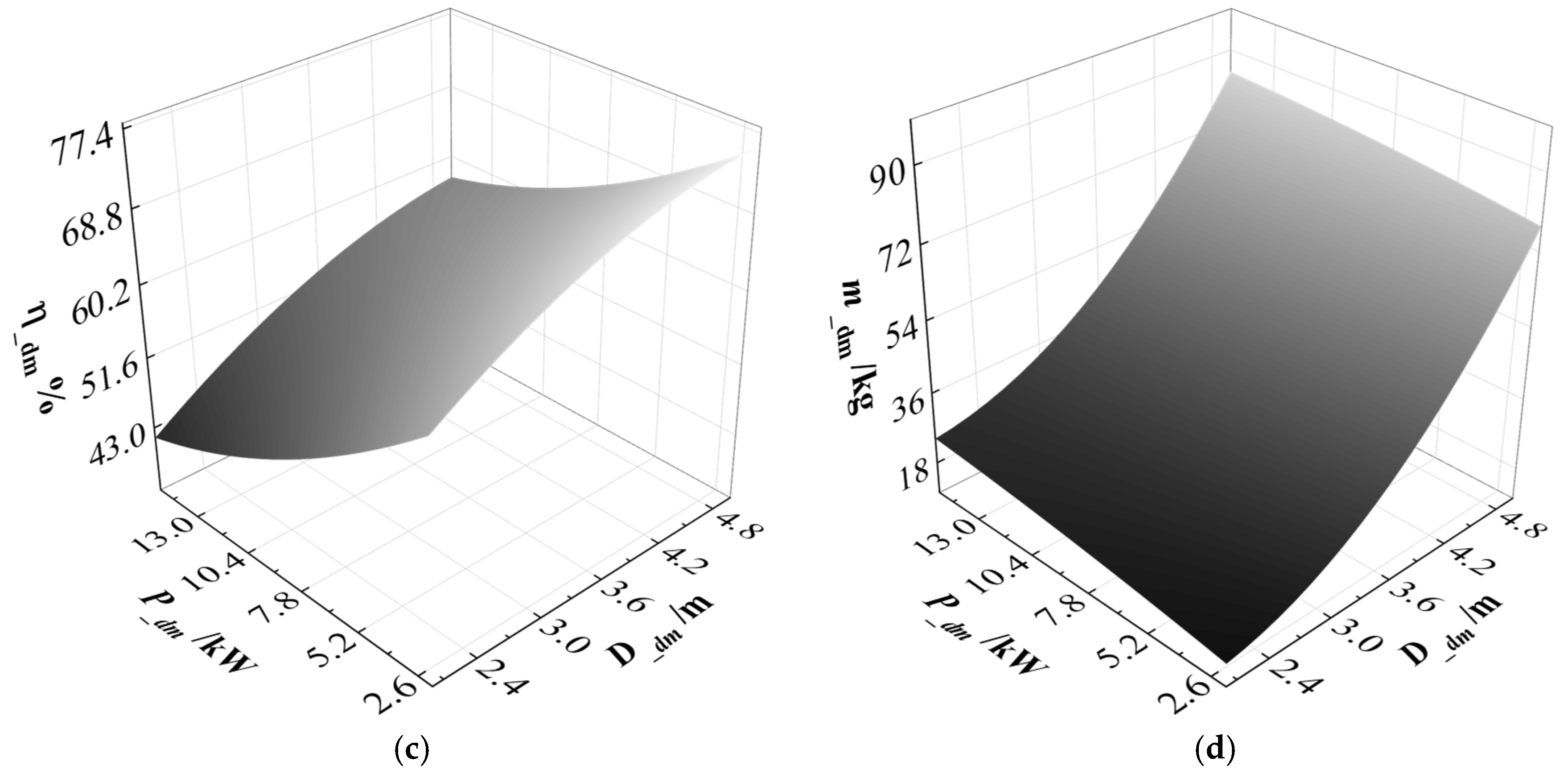
In this study, five-fold cross-validation was adopted to evaluate the prediction accuracy of the surrogate models. The dataset was divided into five approximately equal subsets. In each iteration, four subsets were used for model training and the remaining one for validation [31]. This approach effectively reduces the variance of error estimation while maintaining a relatively low bias. Moreover, the five-fold strategy significantly reduces the computational burden while ensuring reliable evaluation quality. Table 1 shows the average prediction error of each surrogate model. As seen from Table 1, the RSM method exhibits the smallest average error. The surrogate models for motor efficiency and weight constructed using the RSM method are presented in Figure 2.
For each propeller scheme corresponding to the sampled data points, the input power and propeller diameter are given. Engineering calculations are then carried out for contra-rotating propellers and ducted propellers. Since the axial flow characteristics of coaxial contra-rotating propellers are similar to those of coaxial rotors, this study adopts the mutual interference wake superposition model proposed by Valkov [32] for coaxial rotors. An additional circumferential induced velocity term is incorporated to account for swirl effects, enabling the construction of a front-rear propeller interference model. This model is coupled with blade element momentum theory (BEMT) to establish the engineering calculation method for contra-rotating propellers. For ducted propellers, an open-source engineering analysis method developed by Mark Drela and Harold Youngren at the Massachusetts Institute of Technology (MIT) is adopted [33]. Based on the propeller-motor matching principle, the number of blades, chord length distribution, and twist angle distribution are selected as design variables to optimize the entire heterogeneous propeller propulsion system. This process achieves an optimal propeller geometry that satisfies the matching condition between the propeller and motor. Subsequently, structural analysis is conducted using a finite element solver on the optimized aerodynamic shape. Based on the aerodynamic performance and structural weight of each sample, a surrogate model for the propeller is constructed.
To achieve sufficient predictive accuracy, the propulsion system surrogate model is established by applying three representative surrogate modeling methods, namely the quadratic response surface method (RSM), Kriging, and radial basis function (RBF). Five-fold cross-validation is performed for each method, and the average prediction errors are compared, as summarized in Table 2. The results show that the RSM method achieves the lowest average error, and the resulting surrogate models for propeller propulsion system efficiency and weight are illustrated in Figure 3.

3. Optimization Design Model of the Heterogeneous Propeller Propulsion System

3.1. Rapid Optimization Design Process for Heterogeneous Propeller Electric Propulsion System

This study presents a rapid optimization design methodology to determine the optimal configuration ratio of a heterogeneous propeller electric propulsion system for near-space applications. First, an Optimal Latin Hypercube Sampling (OLHS) strategy based on the maximin criterion is employed to construct the design space. For each sampled point, the aerodynamic shape of the contra-rotating propeller is optimized using an engineering-based analysis method to achieve the corresponding maximum aerodynamic efficiency. Similarly, sample points for the ducted propeller are generated using the same sampling approach, and their aerodynamic shapes are optimized via a dedicated engineering model to obtain the optimal aerodynamic efficiencies. In parallel, surrogate models are developed for the performance prediction of both contra-rotating and ducted motors. Based on these models, a rapid optimization framework is established, in which the number of propulsion units, propeller diameter, rotational speed, and motor power are defined as the design variables. The optimization process is subject to multiple constraints, including buoyancy-weight balance, thrust-drag balance, energy balance, and motor-propeller matching. The objective is to minimize the total weight of the propulsion and energy systems. A multi-island genetic algorithm is then applied to solve this mixed-integer optimization problem, enabling the determination of the optimal configuration for the heterogeneous propeller electric propulsion system.

3.2. Objective Function

For a high-altitude unmanned airship, increasing the number of propulsion units reduces the input power required for each unit, thereby improving the overall system efficiency and reducing the weight of the energy subsystem. However, a larger number of propulsion units inevitably increases the total structural weight of the propulsion system. Considering the wind-resistance requirements, there exists an optimal propulsion system configuration that minimizes the total weight of the integrated propulsion and energy system, thereby enhancing the airship’s overall performance. Based on this consideration, the objective function in this study is formulated as the minimization of the total weight of the propulsion and energy system for a high-altitude unmanned airship
min   M T = ( m p n + m e n )
where mpn is the total propulsion system weight and men is the total energy system weight.

3.3. Design Variables

In the optimization model of the high-altitude unmanned airship propulsion system, six design variables are selected to characterize both the contra-rotating propeller system and ducted propeller system. These variables cover the number of propulsion units, input power, and propeller diameter for each propulsion type. Table 3 summarizes the definition, notation, and units of these design variables, which serve as the decision parameters in the optimization process.

3.4. Constraints

3.4.1. Motor-Propeller Matching Constraint

Motor-propeller matching ensures that the rotational speed and power output of the motor are compatible with the operating requirements of the propeller in the propulsion system design. The matching process begins with determining the thrust required from each propeller based on the wind-resistance requirement. Under the given operating conditions, the corresponding propeller rotational speed is obtained from the thrust-speed relationship, and the propeller torque is subsequently calculated. If the torque-speed characteristic curve of the motor at its rated voltage passes through the calculated operating point of the propeller, the matching design requirement is satisfied.
Since the efficiency and weight of the propulsion system are derived from the surrogate models for the motor and the propeller, the following matching conditions must be satisfied:
Constraints :   P c m _ o u t = P c p _ i n , n s _ c m = n s _ c p P d m _ o u t = P d p _ i n , n s _ d m = n s _ d p
where Pcm_out and Pdm_out are the output powers of the contra-rotating motor and ducted motor, respectively; Pcp_in and Pdp_in are the absorbed powers of the contra-rotating propeller and ducted propeller, respectively; ns_cm and ns_cp are the rotational speeds of the contra-rotating motor and propeller, respectively; and ns_dm and ns_dp are the rotational speeds of the ducted motor and propeller, respectively.

3.4.2. Wind-Resistance Thrust-Drag Balance Constraint for High-Altitude Unmanned Airships

A conventional low-drag airship [34] is generally represented by a streamlined hull formed as a body of revolution about the longitudinal axis, as shown in Figure 4. The relationship between its surface area, the airship length la, and the maximum diameter da is expressed as:
S s h = 2.33 d a l a
The total bare-hull drag is the sum of the form drag and the friction drag, which can be written as:
C D = C D V + C F
where CDV and CF are the form-drag coefficient and friction-drag coefficient, respectively. For most airships, the flow over the hull is turbulent, and when Re > 5 × 10⁶, the coefficients can be expressed as [35]:
C D V = C F 4 λ 1 3 + 6 λ 1.2 + 24 λ 2.7 C F = 0.043   R e 1 6
where λ = la/da is the hull fineness ratio, and Re is the Reynolds number.
The hull drag force Dsh is then calculated as:
D s h = 1 2 ρ a i r V 2 S s h C D
where ρair is the air density and V is the freestream wind speed. Accordingly, the power required for the airship to maintain station or cruise against wind is:
P w = D s h V = 1 2 ρ a i r V 3 S s h C D
The thrust-drag balance constraint ensures that the output power of the propulsion system, Pout, is greater than or equal to the power required to overcome the wind, Pw:
The propulsion system output power Pout is calculated as TV, where T is the total propeller thrust and V is the freestream wind speed.

3.4.3. Buoyancy-Weight Balance Constraint of the Airships

The total buoyant force Fsh generated by the airship is given by Formula (8),
F s h = ( ρ a i r ρ H e ) ξ H e V s h
where ρair is the air density, ρHe is the helium density, and ξ H e is the ratio of the helium envelope volume to the total airship volume. Since ρair and ρHe vary with altitude, they can be determined at the station-keeping altitude H from the ideal gas law as Formula (9),
ρ H e = δ H e P a i r R H e T e m
where Tem is the atmospheric temperature at the station-keeping altitude, Pair is the atmospheric pressure at the same altitude, δhe is the pressure difference coefficient of the helium envelope, and RHe is the specific gas constant for helium.
For simplicity, the total mass of the airship msh is defined as the sum of the structural mass mstr, the energy system mass men, the propulsion system mass mpn, and the payload mass mpa, as expressed in Formula (10).
m s h = m s t r + m e n + m p n + m p a
The structural mass of the hull varies with the layout and structural configuration of the airship. For a simple low-drag hull, the structural mass can be estimated by:
m s t r = ρ s h S s h + π d 2 2 + 1 2 ρ b h S s h
where ρsh is the density of the outer skin material and ρbh is the density of the internal envelope skin material.
The energy system mass men is the sum of the solar cell mass mso and the storage battery mass mli:
m e n = m s o + m l i
If the areal density of the solar cells is ρso, then the solar cell mass mso is given by:
m s o = ρ s o S s o = ρ s o W s o E s u n t d η s o
If the energy density of the storage battery is Eli, then the battery mass mli is given by:
m l i = W n η s o _ o u t η l i E l i = P t t n E l i
Assuming that the airship is equipped with identical propulsion units, the total propulsion system mass mpn can be expressed as:
m p n = N ( m p r + m m o + m s u p )
where msup is the mass of the propulsion support structure, which is proportional to the number of propulsion units and the propeller diameter. N denotes the number of propulsion units in the system
The buoyancy-weight balance constraint requires that the total buoyant force Fsh exceeds the total weight of the airship mshg:
Constraints : F s h m s h g 0

3.4.4. Day-Night Energy Balance Constraint for High-Altitude Unmanned Airships

The long-term station-keeping capability of the airship is powered by solar cells. The energy harvested during the day can be divided into two parts: one part is used for station-keeping and maneuvering during the day, and the other is stored in storage batteries to supply power during the night or under insufficient sunlight.
The solar radiation varies significantly with season and location. However, within a specific region, the daily solar radiation is relatively constant. Therefore, for simplification, an energy balance approach is used to estimate the solar energy production over a day-night cycle. The diurnal variation in solar radiation intensity is illustrated in Figure 5, with h1 denoting sunrise and h2 denoting sunset. Aa represents the daytime energy per unit area from the solar cells allocated for storage, while Ab and Ac represent the energy required from the lithium batteries during periods of insufficient sunlight at night. Esun denotes an average solar radiation intensity satisfying ηliAa = Ab + Ac, where ηli is the battery efficiency. Using this average intensity, the energy required for day-night station-keeping can be determined [36].
The daytime solar cell energy allocated to the propulsion system is calculated as:
W d = P i n t d η s o _ o u t
where Pin is the input power of the propulsion system, td is the daytime duration, and ηso_out is the output efficiency of the solar cells.
The energy from the solar cells stored in the batteries is given by:
W n = P i n t n η s o _ o u t · η l i
where tn is the nighttime duration, and ηli is the efficiency of the storage battery.
The total solar cell output energy required for all-day wind resistance is:
W w = W d + W n
The total solar energy Wso absorbed to meet the day-night wind resistance requirement is:
W s o = P s o t d η s o = S s o E s u n t d η s o
where Pso is the solar radiation power received by the solar cells, Sso is the solar cell area, Esun is the solar radiation intensity, ηso is the photoelectric conversion efficiency of the solar cells, and td is the daytime duration.
The day-night energy balance constraint requires that Wso is no less than Ww,
Constraints : W s o W w 0

4. Results and Discussion

4.1. Optimization Results of a Heterogeneous Propeller Propulsion System

To validate the effectiveness of the proposed optimization method for the heterogeneous propeller propulsion system, a conventional propulsion configuration of a high-altitude unmanned airship was adopted as the baseline. The heterogeneous system was subsequently optimized, and the resulting design parameters and the total weight of the integrated propulsion–energy system were compared against those of the baseline configuration. The design operating conditions and selected system parameters of the airship are listed in Table 4.
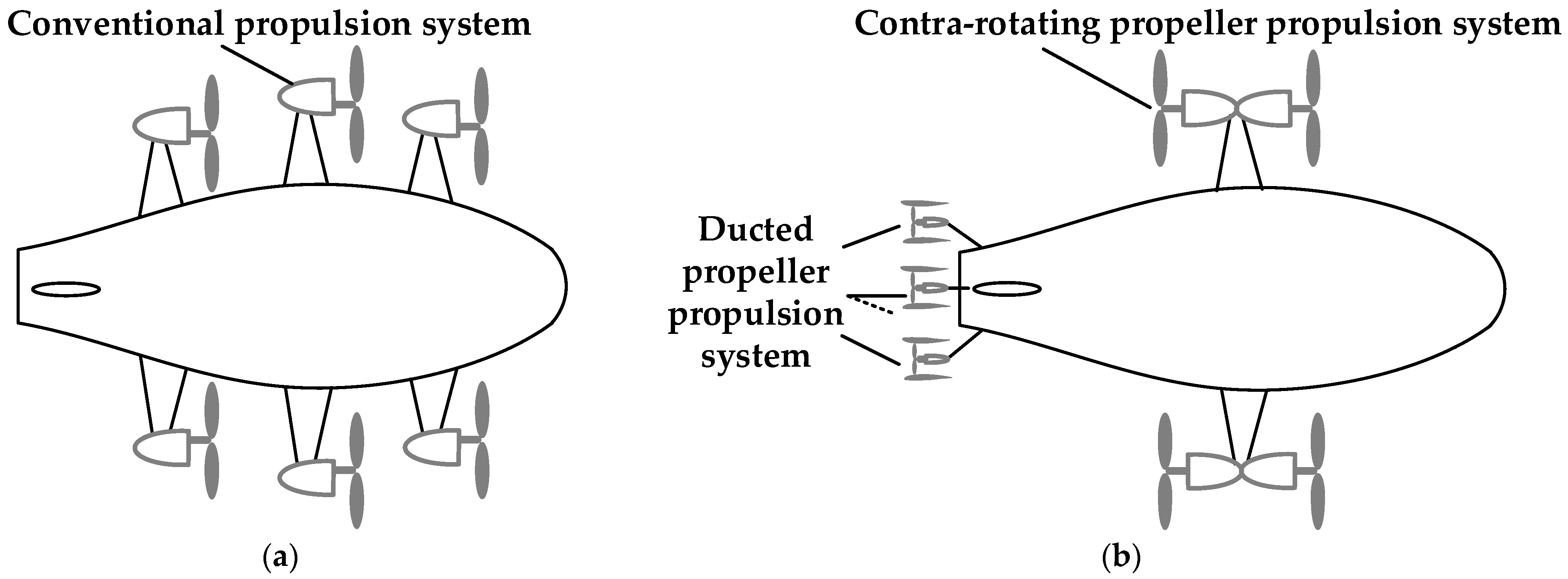
Figure 6 compares the propulsion architectures before and after optimization. In the heterogeneous propeller propulsion system, two contra-rotating propeller units are mounted symmetrically on the airship’s sides, while four ducted propeller units are installed at the tail. This layout was fixed a priori at the preliminary design stage based on engineering practice and system-level constraints. Side-mounted contra-rotating propeller units exploit their high efficiency-to-weight ratio and balance lateral thrust, whereas tail-mounted ducted propellers provide strong thrust under low inflow and enhance yaw control authority; the arrangement also mitigates side inflow blockage and concentrates structural reinforcement at the tail for easier integration. In the baseline configuration, six conventional propeller units are arranged symmetrically along the sides of the hull.
As shown in Table 5, the optimized heterogeneous propulsion layout achieves a marked mass reduction relative to the baseline. The propulsion mass decreases from 250.38 to 195.19 kg, the energy-system mass from 1629.27 to 1034.98 kg, and the total mass from 1879.65 to 1410.93 kg. Under identical wind-resistance conditions, the total weight is reduced by about 468 kg relative to the baseline, representing a 24.9% decrease. This improvement is driven by a lower shaft power together with a modest increase in total disk area, which reduces power loading and hence induced power. Physically, the contra-rotating propellers recover wake swirl and diminish rotational kinetic losses, while the ducted propellers suppress tip-vortex leakage. The contra-rotating and ducted units act synergistically to reduce the average power demand without compromising maneuverability. Within an energy-balance framework, the resulting gain in propulsive efficiency directly reduces daytime photovoltaic and nighttime battery requirements, explaining the larger decrease in energy-system mass. Overall, the heterogeneous arrangement minimizes the coupled propulsion–energy mass while maintaining robust aerodynamic performance for stratospheric station keeping.

4.2. Analysis of Power Unit Configuration Ratios

For various configuration ratios of contra-rotating propeller units and ducted propeller units, the propulsion system weight, propulsion system efficiency, energy system weight, and the total weight of the combined propulsion-energy system were calculated. The configuration schemes and corresponding results are presented in Table 6.
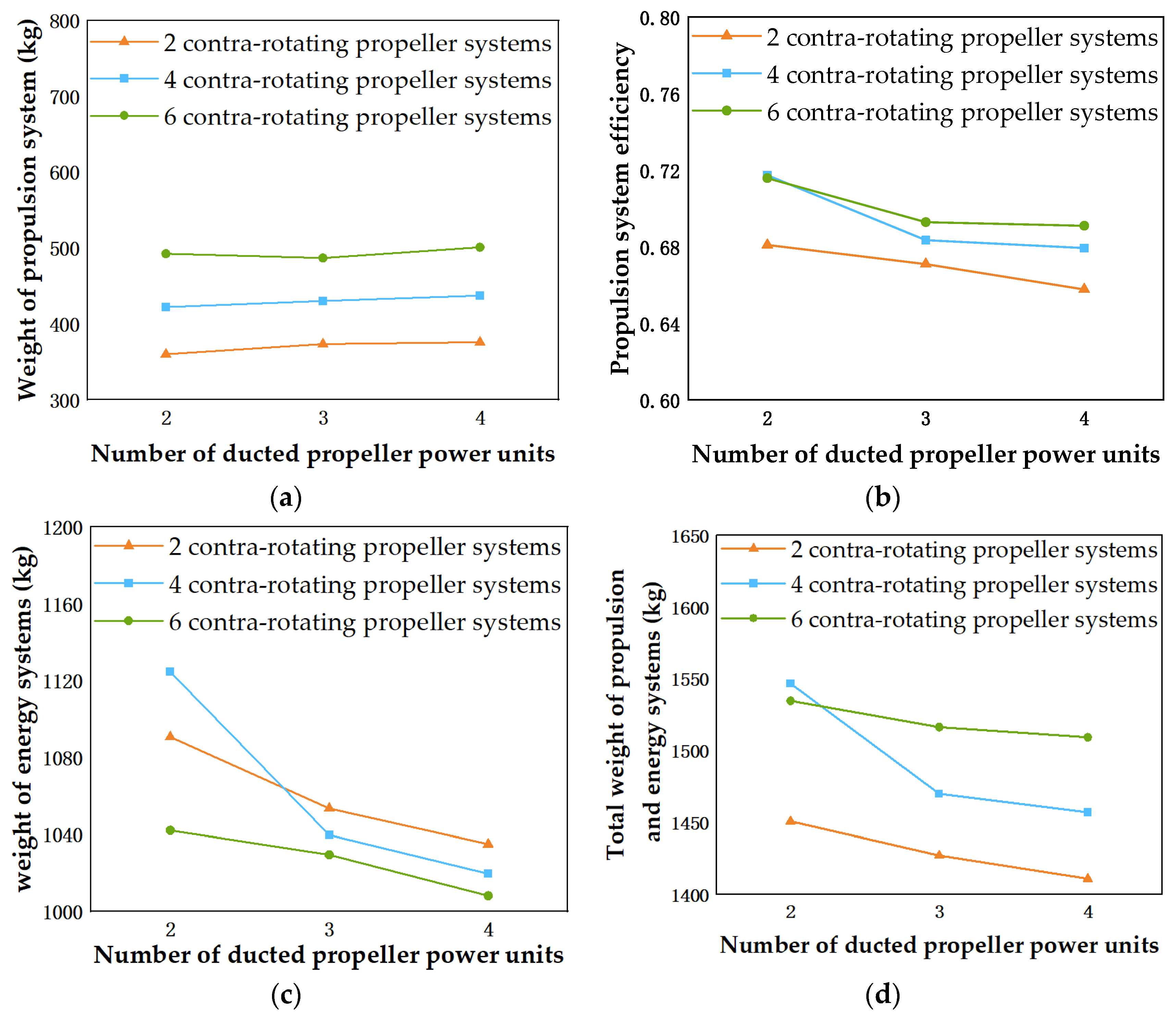
According to the results in Figure 7, the number of ducted propeller power units has a significant impact on the performance indicators of both the propulsion and energy systems. Specifically, Figure 7a shows that as the number of ducted propeller units increases, the total weight of the propulsion system in all contra-rotating propeller configurations generally increases, with the most pronounced change observed in the six-unit contra-rotating system. Figure 7b indicates that propulsion system efficiency decreases with the increase in ducted propeller units, primarily because ducted propellers are mounted at the tail of the airship, where the incoming airflow velocity is relatively low, leading to reduced efficiency. Figure 7c illustrates the variation in total energy system weight, which decreases significantly as the number of power units increases; the reduction is particularly notable in the six-unit contra-rotating system. This reduction is attributed to the decreased energy demand per unit when the load is distributed among more power units, thus optimizing the energy system configuration. It is worth noting that when the number of contra-rotating propellers remains unchanged, the total weight of the energy system decreases as the number of ducted propellers increases. This weight reduction is achieved because the ducted propellers exhibit a higher thrust-to-power ratio compared with contra-rotating propellers. Consequently, to generate the same thrust, ducted propellers require less shaft power, thereby lowering the demand on the energy storage system. According to the optimization results, the thrust-to-power ratio of the contra-rotating propeller is about 1.5, whereas that of the ducted propeller is about 2.5. Figure 7d illustrates the combined weight of the propulsion and energy systems, indicating that the configuration comprising two contra-rotating propeller units and four ducted propeller units yields the minimum total weight, thereby representing the most favorable overall performance.

5. Conclusions

This study presented a novel rapid optimization method for heterogeneous propeller propulsion systems of high-altitude unmanned airships. The main findings are as follows:
  • A fast optimum power unit design method was established, which combines contra-rotating and ducted propellers to minimize the total weight of the propulsion and energy systems under energy balance constraints.
  • The results demonstrate that heterogeneous propulsion configurations can simultaneously reduce energy system weight and improve propulsion efficiency, thereby enhancing the overall endurance capability of high-altitude unmanned airships.
  • Parametric analysis indicates that the optimal allocation of contra-rotating and ducted propeller units plays a decisive role in achieving system-level weight reduction, and the optimization framework enables efficient identification of such configurations.
In summary, the research confirms that incorporating energy balance into the rapid optimization of heterogeneous propulsion systems is an effective approach for achieving lightweight, high-efficiency, and long-endurance performance in high-altitude unmanned airships. The proposed method offers both accuracy and computational efficiency, making it suitable for practical engineering applications and providing valuable insights for the design of future near-space platforms. Nevertheless, several limitations should be acknowledged: (1) the energy balance model adopts average solar input without considering seasonal and geographical variations; and (2) the methodology is primarily intended for preliminary design optimization. Once a preliminary configuration is determined, further refinement through high-fidelity aerodynamic modeling, structural analysis, and experimental testing will be required to achieve detailed engineering design.

Author Contributions

Conceptualization, J.C. and M.Z.; methodology, M.Z.; software, J.C. and Z.Z.; validation, X.W. and B.W.; writing—original draft preparation, M.Z. and X.W.; writing—review and editing, B.W. and J.Z.; funding acquisition, X.W. All authors have read and agreed to the published version of the manuscript.

Funding

This research was funded by the “National Key Laboratory of Science and Technology on Advanced Light-duty Gas-turbine”.

Data Availability Statement

The original contributions presented in this study are included in the article. Further inquiries can be directed to the corresponding author.

Conflicts of Interest

Author Junjie Cheng was employed by the company Anhui Xuanyu Aviation Technology Co., Ltd. The remaining authors declare that the research was conducted in the absence of any commercial or financial relationships that could be construed as a potential conflict of interest.

References

  1. D’Oliveira, F.A.; Melo, F.C.L.D.; Devezas, T.C. High-altitude platforms—Present situation and technology trends. J. Aerosp. Technol. Manag. 2016, 8, 249–262. [Google Scholar] [CrossRef]
  2. Huang, J. Survey on design technology of distributed electric propulsion aircraft. Acta Aeronaut. Astronaut. Sin. 2021, 42, 624037. [Google Scholar]
  3. Riccio, E.; Alifano, F.; Baraniello, V.R.; Coiro, D. A Comprehensive Review of Propeller Design and Propulsion Systems for High-Altitude Pseudo-Satellites. Appl. Sci. 2025, 15, 8013. [Google Scholar] [CrossRef]
  4. Lesieutre, D.J.; Sullivan, J.P. The analysis of counter-rotating propeller systems. SAE Trans. 1985, 94, 564–575. [Google Scholar]
  5. Hager, R.D. Advanced Turboprop Project; Scientific and Technical Information Division, National Aeronautics and Space Administration: Hampton, VA, USA, 1988; Volume 495. [Google Scholar]
  6. Hartman, E.P.; Biermann, D. The Aerodynamic Characteristics of Full-Scale Propellers Having 2, 3, and 4 Blades of Clark Y and RAF 6 Airfoil Sections; Scientific and Technical Information Division, National Aeronautics and Space Administration: Hampton, VA, USA, 1938. [Google Scholar]
  7. Mieloszyk, J.; Galiński, C.; Piechna, J. Contra-rotating propeller for fixed wing MAV: Part 1. Aircr. Eng. Aerosp. Technol. 2013, 85, 304–315. [Google Scholar] [CrossRef]
  8. Qiao, N.; Ma, T.; Fu, J.; Zhang, L.; Wang, X.; Xue, P. Rapid blade shape optimization for contra-rotating propellers for eVTOL aircraft considering the aerodynamic interference. Aerospace 2023, 10, 54. [Google Scholar] [CrossRef]
  9. Zhang, H.; Yang, Y.; Li, P.; Liu, Y.; Li, Q.; Noack, B. Optimal rotation speed combination of contra-rotating rotors for multicopters. In Proceedings of the AIAA AVIATION 2023 Forum, San Diego, CA, USA, 12–16 June 2023; p. 3239. [Google Scholar]
  10. Grunwald, K.J.; Goodson, K.W. Aerodynamic Loads on an Isolated Shrouded-Propeller Configuration of Angles of Attack from −10 Degrees to 110 Degrees; National Aeronautics and Space Administration: Washington, DC, USA, 1962. [Google Scholar]
  11. Yilmaz, S.; Erdem, D.; Kavsaoglu, M.S. Performance of a ducted propeller designed for UAV applications at zero angle of attack flight: An experimental study. Aerosp. Sci. Technol. 2015, 45, 376–386. [Google Scholar] [CrossRef]
  12. Hu, Y.; Qing, J.; Liu, Z.H.; Conrad, Z.J.; Cao, J.N.; Zhang, X.P. Hovering efficiency optimization of the ducted propeller with weight penalty taken into account. Aerosp. Sci. Technol. 2021, 117, 106937. [Google Scholar] [CrossRef]
  13. Akturk, A.; Shavalikul, A.; Camci, C. PIV measurements and computational study of a 5-inch ducted fan for V/STOL UAV applications. In Proceedings of the 47th AIAA aerospace sciences meeting including the new horizons forum and aerospace exposition, Orlando, FL, USA, 5–8 January 2009; p. 332. [Google Scholar]
  14. Akturk, A.; Camci, C. Tip clearance investigation of a ducted fan used in vtol uavs: Part 1—Baseline experiments and computational validation. In Proceedings of the ASME 2011 Turbo Expo: Power for Land, Sea, and Air, Vancouver, BC, Canada, 6–10 June 2011; pp. 331–344. [Google Scholar]
  15. Chen, S.; Song, B.; Wang, H. Exploring optimum power unit of propulsion system for high altitude airship. Proc. Inst. Mech. Eng. Part G J. Aerosp. Eng. 2015, 229, 301–311. [Google Scholar] [CrossRef]
  16. Dongchen, W.; Bifeng, S.; Jun, J.; Haifeng, W. High-altitude airship propulsion system optimal design and experiment based on energy balance. Proc. Inst. Mech. Eng. Part G J. Aerosp. Eng. 2023, 237, 3–16. [Google Scholar] [CrossRef]
  17. Riboldi, C.E.; Rolando, A.; Regazzoni, G. On the feasibility of a launcher-deployable high-altitude airship: Effects of design constraints in an optimal sizing framework. Aerospace 2022, 9, 210. [Google Scholar] [CrossRef]
  18. Kahol, O.; Belan, M.; Pacchiani, M.; Montenero, D. Scaling relations for the geometry of wire-to-airfoil atmospheric ionic thrusters. J. Electrost. 2023, 123, 103815. [Google Scholar] [CrossRef]
  19. Belan, M.; Arosti, L.; Polatti, R.; Maggi, F.; Fiorini, S.; Sottovia, F. A parametric study of electrodes geometries for atmospheric electrohydrodynamic propulsion. J. Electrost. 2021, 113, 103616. [Google Scholar] [CrossRef]
  20. Belan, M.; Terenzi, R.; Trovato, S.; Usuelli, D. Effects of the emitters density on the performance of an atmospheric ionic thruster. J. Electrost. 2022, 120, 103767. [Google Scholar] [CrossRef]
  21. Brown, A.; Xu, H.; Gilmore, C.K.; Barrett, S.R. Solid-state electroaerodynamic aircraft design using signomial programming. J. Aircr. 2024, 61, 280–290. [Google Scholar] [CrossRef]
  22. Lin, D.K.; Simpson, T.W.; Chen, W. Sampling strategies for computer experiments: Design and analysis. Int. J. Reliab. Appl. 2001, 2, 209–240. [Google Scholar]
  23. Sacks, J.; Welch, W.J.; Mitchell, T.J.; Wynn, H.P. Design and analysis of computer experiments. Stat. Sci. 1989, 4, 409–423. [Google Scholar] [CrossRef]
  24. Metropolis, N.; Ulam, S. The Monte Carlo Method. J. Am. Stat. Assoc. 1949, 44, 335–341. [Google Scholar] [CrossRef]
  25. Fang, K.T.; Lin, D.K.J.; Winker, P.; Zhang, Y. Uniform Design: Theory and Application. Technometrics 2000, 42, 237–248. [Google Scholar] [CrossRef]
  26. McKay, M.D.; Beckman, R.J.; Conover, W.J. A Comparison of Three Methods for Selecting Values of Input Variables in the Analysis of Output From a Computer Code. Technometrics 2000, 42, 55–61. [Google Scholar] [CrossRef]
  27. Joseph, R.V.; Hung, Y. Orthogonal-Maximin Latin Hypercube Designs. Stat. Sin. 2012, 18, 171–186. [Google Scholar]
  28. Yi, J.; Li, X.; Xiao, M.; Xu, J.; Zhang, L. Construction of nested maximin designs based on successive local enumeration and modified novel global harmony search algorithm. Eng. Optim. 2017, 49, 161–180. [Google Scholar] [CrossRef]
  29. Zhang, M.; Jiao, J.; Zhang, J.; Zhang, Z. High-Efficiency Data Fusion Aerodynamic Performance Modeling Method for High-Altitude Propellers. Drones 2024, 8, 229. [Google Scholar] [CrossRef]
  30. Jiao, J.; Song, B.-F.; Zhang, Y.-G.; Li, Y.-B. Optimal design and experiment of propellers for high altitude airship. Proc. Inst. Mech. Eng. Part G J. Aerosp. Eng. 2018, 232, 1887–1902. [Google Scholar] [CrossRef]
  31. Kohavi, R. A study of cross-validation and bootstrap for accuracy estimation and model selection. In Proceedings of the 14th International Joint Conference on Artificial Intelligence, Montreal, QC, Canada, 20–25 August 1995; pp. 1137–1143. [Google Scholar]
  32. Valkov, T.V. Aerodynamic loads computation on coaxial hingeless helicopter rotors. In Proceedings of the 28th Aerospace Sciences Meeting, Reno, NV, USA, 8–11 January 1990. [Google Scholar]
  33. Sargent, P.B.; Anemaat, W.A. Benchmarking a robust panel code for ducted fan VTOL aircraft design. In Proceedings of the 2018 Applied Aerodynamics Conference, Atlanta, GA, USA, 25–29 June 2018; p. 4212. [Google Scholar]
  34. Khoury, G.A. Airship Technology; Cambridge University Press: Cambridge, UK, 2012. [Google Scholar]
  35. Kanikdale, T.; Marathe, A.; Pant, R. Multi-Disciplinary Optimization of Airship Envelope Shape. In Proceedings of the 10th AIAA/ISSMO Multidisciplinary Analysis and Optimization Conference, Albany, NY, USA, 30 August–1 September 2004. [Google Scholar]
  36. Wang, H.; Song, B.; Zuo, L. Effect of High-Altitude Airship’s Attitude on Performance of its Energy System. J. Aircr. 2007, 44, 2077–2080. [Google Scholar] [CrossRef]
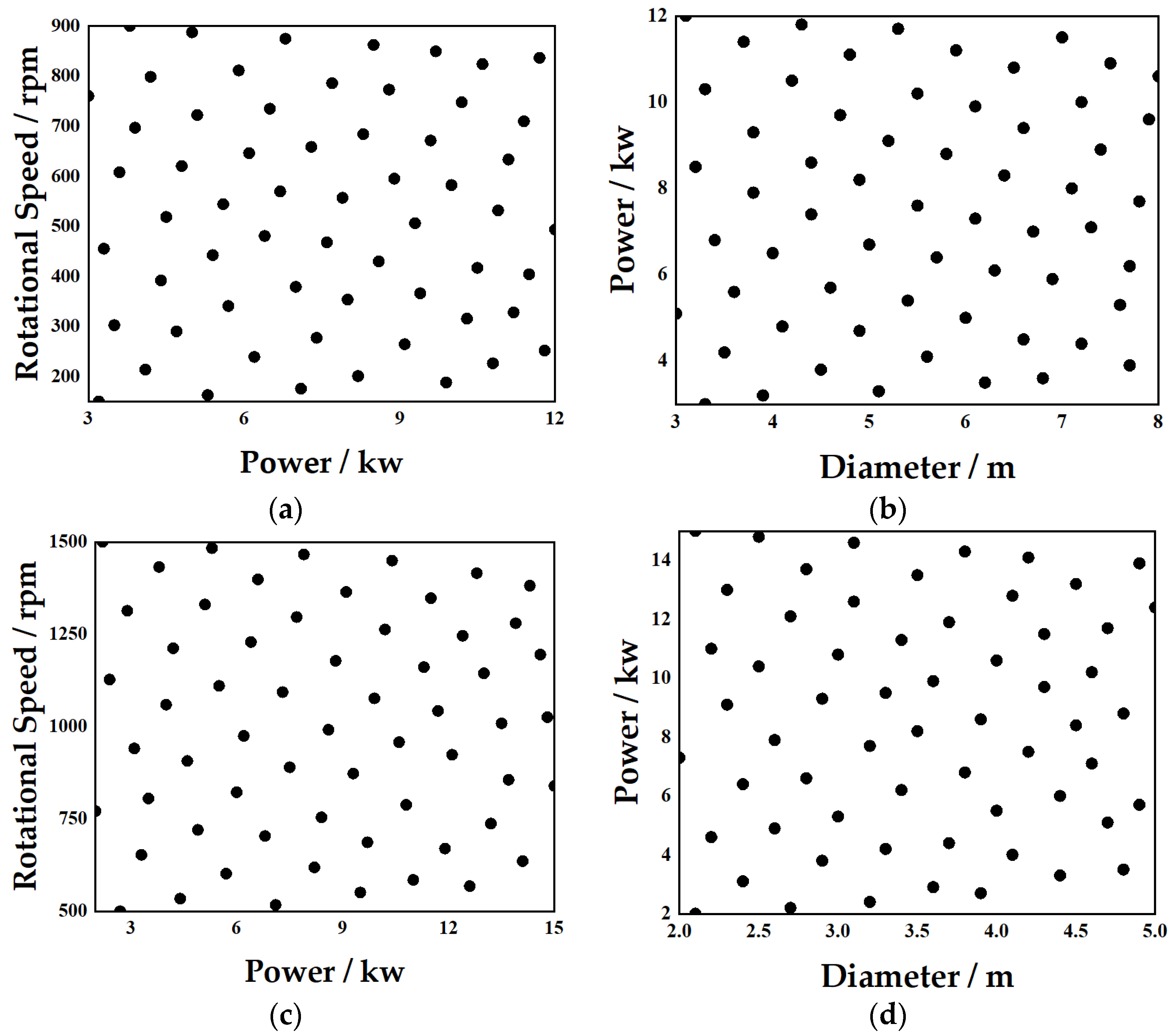
Figure 1. Sample point distribution of the heterogeneous propeller propulsion system. (a) Design space of contra-rotating motor. (b) Design space of contra-rotating propeller. (c) Design space of ducted motor. (d) Design space of ducted propeller.
Drones 09 00718 g001
Figure 2. Surrogate model of the motor. (a) Efficiency surrogate model of contra-rotating motor. (b) Weight surrogate model of contra-rotating motor. (c) Efficiency surrogate model of ducted motor. (d) Weight surrogate model of ducted motor.
Drones 09 00718 g002
Figure 3. Surrogate model of the propeller propulsion system. (a) Efficiency surrogate model of contra-rotating propeller propulsion system. (b) Weight surrogate model of contra-rotating propeller propulsion system. (c) Efficiency surrogate model of ducted propeller propulsion system. (d) Weight surrogate model of ducted propeller propulsion system.
Drones 09 00718 g003aDrones 09 00718 g003b
Figure 4. Baseline low-drag airship hull shape.
Drones 09 00718 g004
Figure 5. Energy balance diagram of the energy system.
Drones 09 00718 g005
Figure 6. Schematic diagrams of the airship configurations before and after optimization. (a) Baseline configuration. (b) Optimal configuration.
Drones 09 00718 g006
Figure 7. Variations in propulsion/energy system performance indicators with different power unit configurations. (a) Total propulsion system weight. (b) Propulsion system efficiency. (c) Total energy system weight. (d) Total weight of propulsion and energy systems.
Drones 09 00718 g007
Table 1. Average error of motor surrogate models.
Surrogate Model MethodContra-Rotating Motor Efficiency ErrorContra-Rotating Motor Weight ErrorDucted Motor Efficiency ErrorDucted Motor Weight Error
RSM0.001%0.054%0.002%0.133%
Kriging0.008%0.322%0.003%0.302%
RBF0.072%2.122%0.047%1.827%
Table 2. Average error of propeller surrogate models.
Surrogate Model MethodContra-Rotating Propeller Efficiency ErrorContra-Rotating Propeller Weight ErrorDucted Propeller Efficiency ErrorDucted Propeller Weight Error
RSM0.636%1.914%1.964%4.268%
Kriging1.377%4.275%2.626%7.167%
RBF0.690%1.999%2.239%7.268%
Table 3. Design variables of optimization.
Design VariableDescriptionUnit
NcpNumber of contra-rotating propeller units/
PcpInput power of contra-rotating propellerskW
DcpDiameter of contra-rotating propellersm
NdpNumber of ducted propeller units/
PdpInput power of ducted propellerskW
DdpDiameter of ducted propellersM
Table 4. Parameters and operating conditions of the optimized case.
ParametersDescriptionValue
HAltitude/km20
VFreestream wind speed/m·s−130
laAirship length/m120
λFineness ratio of the airship4
ζheRatio of helium volume to total envelope volume at operating altitude0.96
δhePressure difference coefficient of the helium envelope1.05
RairSpecific gas constant of air/J·kg−1·K−1287.05
RHeSpecific gas constant of helium/J·kg−1·K−12077
EsunSolar radiation intensity/W·m−21300
ηso_inPhotovoltaic efficiency of solar cells0.28
ηso_outOutput efficiency of solar cells0.95
ρscAreal density of solar cells/kg·m−20.25
ηliCharge–discharge efficiency of energy storage battery0.9
EliEnergy density of energy storage battery/Wh·kg−1280
Table 5. Comparison of propulsion system parameters between baseline and optimal configurations.
ParameterUnitBaseline ConfigurationOptimal Configuration
Number of conventional propulsion units, N/6/
Number of contra/rotating propeller units, Nc//2
Number of ducted propeller units, Nd//4
Diameter of conventional propeller, Dm5.0/
Diameter of contra/rotating propeller, Dcm/7.1
Diameter of ducted propeller, Ddm/3.8
Power of conventional propeller, PkW14.0/
Power of contra/rotating propeller, PckW/14.27
Power of ducted propeller, PdkW/6.67
Total weight of propulsion system, mprkg250.38195.19
Weight of energy system, menkg1629.271034.98
Total weight of propulsion and energy systems, mtotalkg1879.651410.93
Reduction in total weight compared with baseline%/24.94
Table 6. Power unit configuration schemes of the airship and comparison of system weights and efficiencies.
Contra-Rotating Propeller UnitsDucted Propeller UnitsTotal Propulsion System Weight (kg)Propulsion System Efficiency (%)Total Energy System Weight (kg)Total Weight of Propulsion and Energy Systems (kg)
22360.0968.091090.681450.77
23373.6267.101053.481427.10
24375.9565.771034.981410.93
42422.2171.731124.531546.74
43430.2868.351039.691469.97
44437.3767.931019.641457.01
62492.5971.591042.101534.69
63486.8969.291029.511516.40
64501.0569.891008.211509.26
Disclaimer/Publisher’s Note: The statements, opinions and data contained in all publications are solely those of the individual author(s) and contributor(s) and not of MDPI and/or the editor(s). MDPI and/or the editor(s) disclaim responsibility for any injury to people or property resulting from any ideas, methods, instructions or products referred to in the content.