Abstract
For unmanned aerial vehicles (UAVs), high-precision measurement and high-speed communication are necessary to realize flight and operational missions. In this paper, we propose an integrated communication and measurement system in a Doppler frequency offset environment. The system combines orthogonal frequency division multiplexing (OFDM) modulation with binary offset carrier (BOC) modulation to formulate an OFDM+BOC composite signal through power control. High-precision measurement is achieved through BOC modulation, and high data transmission is achieved through OFDM modulation. Furthermore, the high-precision Doppler frequency offset tracked by the BOC signal is adopted to assist in the demodulation of the OFDM signal. This substantially decreases the impact of the Doppler frequency offset on the OFDM signal. Moreover, the ranging error is within , and the maximum Doppler frequency error is within 2 Hz.
1. Introduction
In recent years, unmanned aerial vehicles (UAVs) have become an important part of modern military development [1]. For UAVs, high-precision measurement and high-speed information transmission are necessary to realize flight and operational missions. Previously, communication and measurement functions have been designed independently to achieve high performance and reduce mutual interference. However, as the number and types of UAVs continue to increase, problems may arise between the various independent systems such as complex management, waste of resources, and difficulty in effective interaction. Therefore, the integration of communication and measurement is a general trend for future development [2,3,4,5].
Many scholars in related fields have conducted numerous studies on integrated communication and measurement systems. Ref. [6] proposes the time and code division-orthogonal frequency division multiplexing (TC-OFDM) signal system for the integration of communication and measurement. By superimposing the ranging signal onto the orthogonal frequency division multiplexing (OFDM) signal, the TC-OFDM signal is simultaneously realized with signal acquisition and tracking. Ref. [7] proposes a method for simultaneous ranging and communication based on the physical layer (PHY) of multiband orthogonal frequency division multiplexing (MB-OFDM). The transmitter modulates one or multiple OFDM subcarriers with a low-frequency ranging signal, and the remaining subcarriers are adopted for communication. This approach requires a signal-to-noise ratio (SNR) greater than 15 dB to achieve a 1% range accuracy without interference. Ref. [8] proposes a two-step carrier phase estimation method for OFDM signal to improve the position accuracy. Although the proposed method can achieve sub-centimeter accuracy, it fails to realize communication. In addition, Ref. [9] proposes an integrated navigation and communication system based on OFDM in different scenarios. The authors combine the block-type ranging pilot with the OFDM signal. The accuracy of the ranging error can reach 0.8 m. Refs. [10,11] indicate that OFDM can possess combined communication and measurement capabilities and can provide an efficient spectrum utilization rate. Although many scholars have realized integration of communication and measurement based on OFDM modulation, the resulting systems have rarely met the high-precision measurement requirements.
Refs. [12,13] show that the modulation scheme has an important impact on the accuracy. The initial modulation scheme was a binary phase shift keying-rectangular (BPSK-R) modulation [14]. However, improving the accuracy requires endowing BPSK modulation with a wider bandwidth and better multipath performance [15]. To solve these problems, Betz proposes a binary offset carrier (BOC) modulation [16,17]. BOC modulation has significant benefits in terms of good spectral isolation from heritage signals, high-precision measurement, resistance to multipath interference, and flexible signal implementation [14]. Presently, BOC modulation is broadly adopted in modern global navigation satellite systems such as the Global Positioning System (GPS) [18], the European Galileo System [16], and the Beidou Navigation System (BDS) [19]. Ref. [20] proposes a multifunctional signal based on BOC and BPSK modulations. This methodology can achieve communication and measurement functions at the same frequency, and a 1% ranging accuracy is achieved when the carrier-to-noise ratio (CNR) is greater than 60 dB-Hz. Ref. [21] proposes a signal modulation method based on OFDM, combining the direct sequence spread spectrum and OFDM modulation technologies. High tracking accuracy is achieved by adopting high-frequency subcarriers to increase the energy of high-frequency signals. Many relevant works have combined OFDM or BOC modulation with other systems to achieve the integration of communication and measurement. However, researchers have rarely considered combining the OFDM system with the BOC system. Ref. [13] realizes the combination of the OFDM system and the BOC system; however, they do not consider the influence of the Doppler frequency offset on the OFDM system. Due to the characteristics of the subcarriers and the high-speed motion, the OFDM signal is extremely susceptible to the Doppler frequency offset [22]. The Doppler frequency offset can degrade the orthogonality between subcarriers, leading to intercarrier interference, which considerably decreases the communication performance.
In this paper, we propose an integrated communication and measurement system under a Doppler frequency offset environment. The system adopts OFDM modulation to achieve a high transmission rate and BOC modulation to achieve high-precision ranging. We utilize the orthogonality of the OFDM subcarriers and the spectral characteristics of BOC modulation to formulate an OFDM+BOC composite signal through power control. Furthermore, we adopt the high-precision Doppler frequency offset tracked by the BOC signal to assist in the demodulation of the OFDM signal. This approach can considerably reduce the impact of the Doppler frequency offset on the OFDM signal. Moreover, a significant improvement in the measurement accuracy is achieved.
The overall structure of this paper is divided into six sections, including this introductory section. Section 2 begins by introducing the structures of the transmitting and receiving systems and discusses how to design the composite signal. Section 3 presents the process of receiving the composite signal, focusing on three key aspects: acquisition, tracking of the BOC system, and demodulation of the OFDM system. Section 4 examines the performance of the composite signal. Section 5 and Section 6 present a discussion and conclusions regarding the composite signal.
2. The Transmitting and Receiving System for the Composite Signal
In this section, we present the composite signal model and introduce the structure of the transmitting and receiving systems.
2.1. Signal Model
The composite signal designed in this paper consists of two parts: the BOC signal and the OFDM signal. The BOC signal is applied for measurement, and the OFDM signal is applied for communication. The main idea of the BOC signal is to modulate a square-wave subcarrier via spread spectrum modulation to shift the power spectrum from the central frequency to both sides [23,24]. Consequently, the BOC signal is equivalent to a pseudorandom code sequence multiplied by a square-wave subcarrier. Moreover, the BOC signal energy is concentrated at the edges of the frequency band, thus making full use of the frequency band resources [25]. Mathematically, the BOC signal is expressed as Equation (1):
where denotes the pseudorandom code signal and denotes the modulated square-wave subcarrier signal. There are two types of square-wave subcarrier signals: sine and cosine [13]. Their time-domain expressions are as follows:
where is the sign function and is the square-wave subcarrier frequency.
The main idea of the OFDM signal is that the channel is divided into orthogonal subchannels and data are transmitted on the subchannels in a parallel/orthogonal manner. The OFDM modulation process is as follows. First, the serial data bits are encoded, interleaved, and digitally modulated, after which the pilot is inserted to obtain the symbol vector , where represents the kth symbol transmitted on the mth subcarrier, with and . Second, serial to parallel (S/P) conversion is executed to obtain parallel subdata bits. Finally, the inverse fast Fourier transform (IFFT) is applied to the parallel subdata bits to generate the OFDM signal. Here, each data symbol output through the IFFT is generated via the superposition of all subcarrier signals. Mathematically, the discrete-time OFDM symbol is expressed as Equation (3):
In this paper, the proposed composite signal makes use of the orthogonality of the OFDM subcarriers and the spectral characteristics of the BOC signal, and BOC modulation and OFDM modulation are combined through power control. A block diagram of the transmitting system is shown in Figure 1.
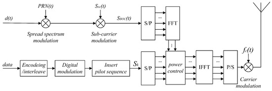
Figure 1.
Transmitting system for the composite signal.
The composite signal transmission process is as follows.
First, the ranging message is modulated by the spread spectrum and square-wave subcarrier methods to generate the fundamental frequency BOC signal.
Second, the serial data are obtained by inserting the pilot after the communication message is encoded, interleaved, and digitally modulated. Convolutional coding is adopted for coding, and quadrature phase shift keying (QPSK) modulation is adopted for digital modulation.
Third, parallel subcarriers and are obtained through the S/P conversion of and , respectively. Note that the parallel subcarriers both need to be subjected to the fast Fourier transform (FFT) before power control, as shown in Equation (4):
where denotes the uth symbol transmitted on the bth subcarrier, with and . This is designed to ensure that the BOC signal at the transmitter is not compromised by the following IFFT. Moreover, to facilitate power control, the numbers of subcarriers and symbols should be consistent with those of OFDM, namely, , , and .
Meanwhile, to avoid interference in the demodulation of the OFDM signal caused by the peak of the main lobe of the BOC signal, the OFDM subcarrier signal corresponding to the subcarrier of the main lobe of the BOC signal is set to zero, namely, the OFDM signal does not exist at this subcarrier. Thus, orthogonality between the main lobe of the BOC signal and the OFDM signal is ensured. Furthermore, the power of the sidelobes of the BOC signal is sufficiently small to be equivalent to noise. Figure 2 shows the spectrum diagram of the fundamental frequency BOC (4, 1) signal, from which the sidelobe power is observed to be 15 dB lower than the main lobe power. Therefore, the interference with the OFDM signal is negligible.
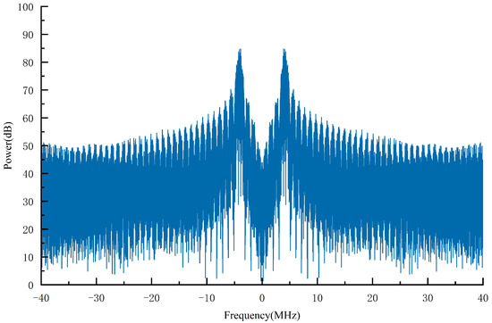
Figure 2.
Spectrum diagram of the fundamental-frequency BOC (4, 1) signal (the square-wave subcarrier frequency is 4.096 MHz; the code frequency is 1.023 MHz).
Fourth, the IFFT is applied after power control between and . Equation (5) is derived by combining Equations (3) and (4):
Finally, the serial data bits are obtained through parallel to serial (P/S) conversion, and carrier modulation is performed. Here, the function of carrier modulation is to shift the signal from the fundamental frequency to a high frequency. In conclusion, the composite signal is expressed as Equation (6):
where and are the power ratios of the OFDM signal and the BOC signal, respectively, satisfying ; is the carrier signal; is the carrier frequency; and is additive white Gaussian noise.
According to the frequency-domain sampling theorem [26], when the number of frequency-domain sampling points is greater than or equal to the length of the signal sequence, the original signal sequence can be recovered from the frequency-domain sampling. Thus, the following equation is obtained:
Hence, by combining Equations (6), (7), and (3), one finds that the composite signal is equivalent to Equation (8):
where and are the high-frequency OFDM signal and BOC signal after carrier modulation, respectively.
The spectrum diagram of the composite signal is shown in Figure 3. The number of OFDM subcarriers must be . Therefore, the number of subcarriers is selected to be . Based on the BOC signal characteristics of spectrum symmetry and being located on both sides of the central frequency, only the main lobe of the BOC signal exists in the subcarriers (blue subcarriers), namely, . The OFDM signal and the side lobe of the BOC signal are superposed in the remaining subcarriers (red subcarriers) in according with their power ratios. The spectrum of the composite signal in this paper is shown in Figure 4.
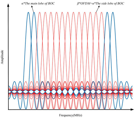
Figure 3.
Spectrum diagram of the composite signal (The main lobe of the BOC signal only exists in the blue subcarriers, and the OFDM signal and the side lobe of the BOC signal are superposed in the red subcarriers through power control).
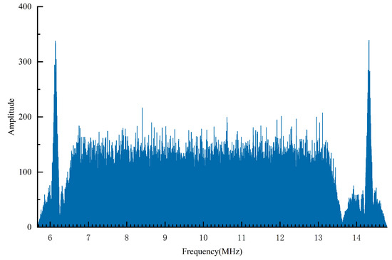
Figure 4.
Spectrum of the composite signal (the carrier frequency is 10.23 MHz; the square-wave subcarrier frequency is 4.096 MHz; the code frequency is 1.023 MHz).
2.2. Reception of the composite signal
The reception of the composite signal is divided into two parts: demodulation of the OFDM signal and reception of the BOC signal, as shown in Figure 5. The reception of the BOC signal is further divided into two stages: acquisition and tracking. The main focus of the acquisition stage is to roughly estimate the Doppler frequency offset and code phase offset. After acquisition, high-precision estimation of the BOC signal parameters is realized through tracking. Additionally, the high-precision parameters tracked by the BOC signal can assist in the demodulation of the OFDM signal, decreasing the bit error rate (BER) and improving the communication performance.
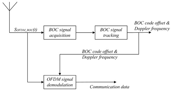
Figure 5.
Reception of the composite signal.
Since the BOC signal and the OFDM signal share the same frequency spectrum, the two signals have the same frequency. Moreover, the BOC signal adopts a pseudorandom code spread spectrum, which has high anti-interference performance. Therefore, the parameters of the BOC signal are used to assist in the demodulation of the OFDM signal, as described in Section 3.
3. Reception of the Composite Signal
In this section, we introduce the process of receiving the BOC signal and the OFDM signal. First, we introduce the correlation between the BOC signal and the OFDM signal. Then, we design the receiving system for the composite signal, which performs acquisition and tracking of the BOC signal and demodulation of the OFDM signal.
3.1. Independence of the Reception of the BOC and OFDM Signals
The main basis of BOC signal acquisition and tracking is the correlation function between the received signal and the local BOC signal. This means that the high-precision Doppler frequency offset and code phase offset of tracking are obtained through correlation. The correlation function, ignoring noise, is shown in Equation (9):
where is the received signal and denotes the locally generated BOC signal. is the auto-correlation function of the BOC signal, as shown in Figure 6a. is the correlation function of the BOC and OFDM signals, as shown in Figure 6b.
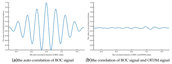
Figure 6.
Auto-correlation function of the BOC signal and correlation function of the BOC and OFDM signals (BOC (4,1) is adopted; the square-wave subcarrier frequency is 4.096 MHz; the code frequency is 1.023 MHz). (a) shows the auto-correlation function of the BOC signal. (b) shows the correlation function of the BOC and OFDM signals.
As shown in Figure 6, the normalized correlation function between the BOC and the OFDM signals is considerably lower than the normalized auto-correlation function of the BOC signal. According to the results, the correlation function of the BOC and OFDM signals can be neglected. Thus, Equation (9) is rewritten as Equation (10):
Hence, the acquisition and tracking of the BOC signal are minimally affected by the OFDM signal. Moreover, Section 2.1 indicates that the subcarriers in which the BOC signal’s main lobe is located do not contain the OFDM signal, and the power of the sidelobes of the BOC signal is 15 dB lower than the power of main lobe. This means that the BOC signal sidelobes are equivalent to noise for the OFDM signal. Therefore, demodulation of the OFDM signal is minimally affected by the BOC signal. In conclusion, the BOC and OFDM signals are independently received.
3.2. Acquisition of the BOC Signal
Acquisition algorithms are generally two-dimensional search processes of the code and Doppler dimensions [27]. The main function of the acquisition algorithm is to roughly estimate the code phase offset and Doppler frequency offset. The parallel code phase acquisition algorithm [28] is applied in this paper and is described below.
First, the received signal is mixed with the local sine and cosine carrier signals to obtain the I/Q branches.
Second, the FFT is applied to the signal and to the local BOC signal and its conjugate.
Subsequently, the above two signals are multiplied after the FFT and conjugation, and the IFFT is applied to the result of this multiplication.
Finally, the modulus is taken to find the maximum correlation peak. When the maximum correlation peak exceeds a preset acquisition threshold, the acquisition is considered successful. Otherwise, the local carrier frequency is adjusted and the above process is repeated until the output maximum correlation peak exceeds the preset acquisition threshold. If all carrier frequencies are traversed and the preset acquisition threshold still is not exceeded, then the acquisition is considered to have failed. The block diagram of parallel code phase acquisition is shown in Figure 7.
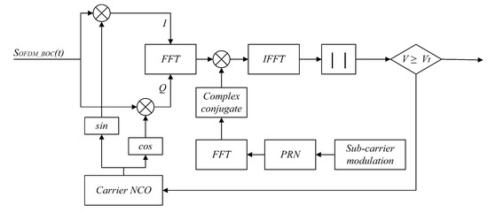
Figure 7.
Parallel code phase acquisition algorithm.
3.3. Tracking of the BOC Signal
Based on the roughly estimated code phase offset and Doppler frequency offset results, the tracking stage estimates the parameters of the received signal with high precision. There are three major traditional tracking algorithms for the BOC signal: BPSK-Like [29], ASPeCT [30], and Bump-Jump [31]. However, these approaches have limitations. For example, BPSK-Like occupies a large amount of hardware resources and does not fully utilize the benefits of the BOC signal, ASPeCT is designed only for sin-BOC(n,n) signals and is not suitable for other types of BOC signal, and Bump-Jump cannot be applied in highly dynamic scenarios. To compensate for the deficiencies of these tracking algorithms, a subcarrier phase-locked loop (SPLL) three-loop tracking algorithm is proposed to estimate the code phase offset and Doppler frequency offset with high precision.
As shown in Figure 8, the SPLL three-loop tracking algorithm is mainly composed of a carrier tracking loop, a subcarrier tracking loop, and a code tracking loop. The numerically controlled oscillators (NCOs) of the three loops can generate a local signal based on the feedback from their respective discriminators.
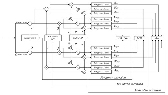
Figure 8.
SPLL three-loop tracking algorithm.
The carrier tracking loop uses a second-order frequency-locked loop (FLL) to assist a third-order phase-locked loop (PLL) [32] and has excellent performance under highly dynamic conditions. The fast tracking capability of the FLL and the high tracking precision of the PLL are fully exploited in the carrier tracking loop. A Costas loop design is used in both the FLL and PLL, and the discriminators are shown in Equations (11) and (12), respectively:
In Equation (11), and are the cross product and dot product of the branches, respectively, as shown in Equations (13) and (14):
where and represent the integration and dumping results for the in-phase prompt branches, respectively, and and are the integration and dumping results, respectively, for the branches at the last integration time.
The subcarrier tracking loop employs a third-order PLL, and the phase discriminator is shown in Equation (15):
where and represent the integration and dumping results for the orthogonal prompt branches, respectively.
The code tracking loop adopts a delay-locked loop (DLL), which adjusts the code NCO in accordance with the code phase offset between the received signal pseudocode and the local signal pseudocode. Subsequently, the phase of the received signal is kept consistent with the phase of the local signal through cyclic feedback to achieve the tracking and locking of the code phase. The normalized incoherent early-delayed amplitude methodology is adopted in the loop phase discriminator, as shown in Equation (16):
where d is the early–delayed correlation spacing and E and L are the amplitudes of the early and delayed branches, respectively, as shown in Equations (17) and (18):
where , , , and are the integration and dumping results for the four early branches and , , , and represent the integration and dumping results for the four delayed branches.
Notably, the carrier tracking loop, subcarrier tracking loop and code tracking loop are independent of each other and do not interfere with each other.
3.4. Demodulation of the OFDM Signal
The OFDM signal is the superposition of multiple subchannel signals, and the subcarriers are distinguished by orthogonality. However, when the Doppler frequency offset exceeds a threshold, interference may occur between subchannels, resulting in the degradation of the communication performance. Therefore, reducing the influence of the Doppler frequency offset on the OFDM signal is a key issue for enhancing the performance of UAV communication systems under high-speed mobile conditions. Consequently, we propose an approach for using the BOC signal to assist in the demodulation of the OFDM signal, as shown in Figure 9.
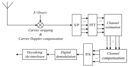
Figure 9.
Demodulation of the OFDM signal.
In Section 3.3, we obtain a Doppler frequency offset with high precision through the SPLL three-loop tracking algorithm. The high-precision Doppler frequency offset tracked by the BOC signal is adopted for carrier Doppler compensation to assist in the demodulation of the OFDM signal.
Let the signal received after it passes through the channel be . Considering that the BOC signal has little influence on OFDM demodulation, the received OFDM signal can be expressed as follows:
Subsequently, carrier stripping and carrier Doppler compensation are performed on the received OFDM signal, as shown in Equation (20):
where is the carrier frequency, is the channel Doppler frequency, and is the high-precision Doppler frequency offset obtained through the SPLL three-loop tracking algorithm. Let , when becomes infinitely close to , , and .
Subsequently, the signal is subjected to S/P conversion, and the FFT is applied to obtain parallel subdata bits , where denotes the kth symbol received on the mth subcarrier, with and . Channel estimation and channel compensation are further carried out. For channel estimation, least squares (LS) channel estimation based on comb-type pilots [33] is adopted. In Figure 10, the blue subcarriers contain only the main lobe of the BOC signal, the gray subcarriers contain the pilot information, and the white subcarriers contain the received signal to be demodulated. We denote the transmitted pilot information by and the pilot information received by , where m and d represent the dth symbol received on the mth subcarrier. In this paper, the pilot positions are the 3rd, 7th, and 11th subcarriers. Thus, the channel transmission function of the pilot subcarrier can be estimated as follows:
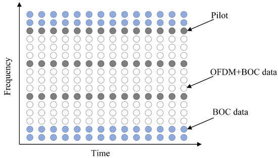
Figure 10.
Comb-type pilots.
Once the channel transmission function of the pilot subcarriers has been estimated, the channel transmission function of the data subcarriers can be obtained through linear interpolation [34]. Subsequently, we perform channel compensation on the received signal in accordance with the channel transmission function, as shown in Equation (22). Finally, QPSK demodulation and Viterbi decoding are performed to recover the received signal.
4. Simulation Results and Performance Analysis
In this section, we study the performance in terms of composite signal acquisition, tracking, and the BER.
4.1. Channel Model
In this paper, the Jakes channel model [35] based on the sine wave superposition method and the additive white Gaussian noise (AWGN) channel model are adopted. The sine wave superposition method relies on deterministic processes to simulate random processes and generates Rayleigh fading channels with a given Doppler spectrum through sine wave synthesis. The simulation parameters are shown in Table 1.

Table 1.
Simulation parameters.
4.2. Acquisition Performance
The acquisition performance is mainly determined by three parameters: the success probability of a single acquisition, ; the false alarm probability, ; and the false dismissal probability, . These three parameters are obtained through repeated detection and statistics based on the Monte Carlo algorithm, as shown in Figure 11 and Figure 12 (since the false alarm probability is approximately equal to zero, it is not shown in a figure). Figure 11 shows the success probability of single acquisition under different power ratios and different CNRs. As shown in Figure 11, the success probability of a single acquisition, , is not significantly different when : = 0.5:0.5 and : = 0.4:0.6 and when , ; when the CNR increases to , . However, the performance gradually deteriorates as the power ratio further decreases. To achieve , the requirements are as follows: when : = 0.3:0.7, ; when : = 0.2:0.8, ; and when : = 0.1:0.9, . In summary, as the power ratio decreases, the performance in terms of the success probability of single acquisition degrades.
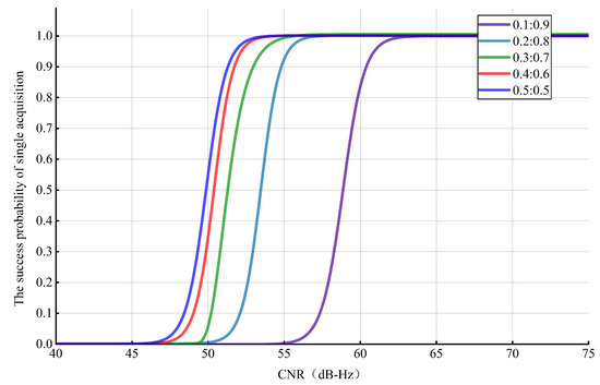
Figure 11.
Success probability of single acquisition under different conditions.
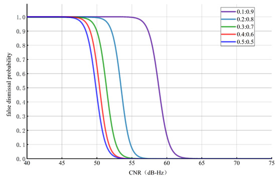
Figure 12.
False dismissal probability under different conditions.
Figure 12 illustrates the false dismissal probability under different power ratios and different CNRs. As displayed in Figure 12, the false dismissal probability, , is not considerably different when : = 0.5:0.5 and : = 0.4:0.6, and when , . When the CNR increases to , . However, the performance gradually deteriorates as the power ratio further decreases. To achieve , the requirements are as follows: when : = 0.3:0.7, ; when : = 0.2:0.8, ; and when : = 0.1:0.9, . In summary, as the power ratio decreases, the performance in terms of the false dismissal probability degrades.
As the power ratio decreases, the acquisition performance gradually deteriorates. The main factor influencing the degradation of the acquisition performance is the reduction in the proportion of the BOC signal in the composite signal. Moreover, the proportion of the OFDM signal may have an impact on the acquisition process, resulting in a decline in the acquisition performance. Therefore, when the CNR is below , the use of : = 0.3:0.7 is reasonable. When the CNR exceeds , the acquisition performance is no longer affected by the power ratio. Thus, a reduction in the proportion of the BOC signal can improve the communication performance and decrease the BER.
4.3. Tracking Performance
The tracking performance for the BOC signal is mainly determined by two factors: the ranging error, which is reflected in the ranging error of the code tracking loop, and the velocity measurement error, which is reflected in the Doppler measurement error.
The ranging error of the code tracking loop is shown in Equation (23):
where d is the chip interval of the code tracking loop, is the DLL bandwidth, is the CNR, is the integration time of the loop, and is the wavelength of the BOC signal.
The Doppler measurement error is determined by the carrier’s third-order PLL and includes thermal noise vibration error and dynamic stress error, as shown in Equation (24):
where is the thermal noise vibration error, is the dynamic stress error, is the third-order PLL bandwidth, and is the acceleration of the system.
The Doppler frequency is calculated as shown in Equation (25):
where is the update time of the Doppler measurement.
Figure 13 illustrates the results for the ranging error of the code tracking loop under different power ratios and different CNRs. Figure 14 exhibits the results for the Doppler frequency measurement error under different power ratios and different CNRs. We can draw the following conclusion: when , the ranging error of the code tracking loop and the Doppler frequency measurement error increase with the decreasing power ratio. Otherwise, the ranging error and Doppler frequency measurement error are almost unaffected by the power ratio.
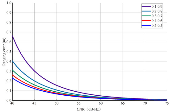
Figure 13.
Ranging error under different conditions.
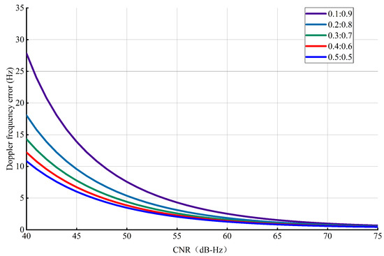
Figure 14.
Doppler frequency measurement error under different conditions.
4.4. The Peak to Average Power Ratio (PAPR) Reduction Capacity of the Composite Signal
The PAPR is defined as the ratio of the peak power to the average power of the transmitted signal. It is statistically analyzed via calculation of the complementary cumulative distribution function (CCDF) by determining the probability of occurrence of a set of PAPR levels. Figure 15 shows the PAPR reduction capacity of the proposed OFDM+BOC system for different power ratios (: = 0.1:0.9, 0.2:0.8, 0.3:0.7, 0.4:0.6, 0.5:0.5) determined via the CCDF. Compared to the original OFDM system, the difference in the PAPR reduction capacity of our proposed OFDM+BOC system is not significant, with a maximum difference of 0.8 dB. Moreover, the PAPR reduction capacity of the composite signal with a power ratio of 0.1:0.9 is almost the same as that of the original OFDM system.
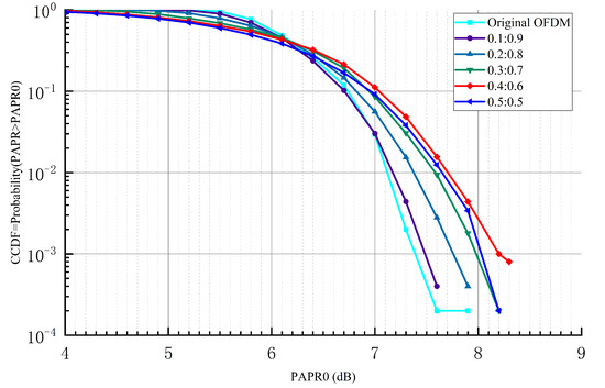
Figure 15.
PAPR performance comparison between the original OFDM system and the proposed OFDM+BOC system.
4.5. Demodulation Performance
To evaluate the demodulation performance for the composite signal proposed in this paper, the composite signal is simulated under different Doppler frequency offsets (), different power ratios (: = 0.5:0.5, 0.4:0.6, 0.3:0.7, 0.2:0.8, 0.1:0.9), and different SNRs. In addition, the BERs of the composite signal with carrier Doppler compensation and with channel compensation are compared. The simulation results are shown in Figure 16.
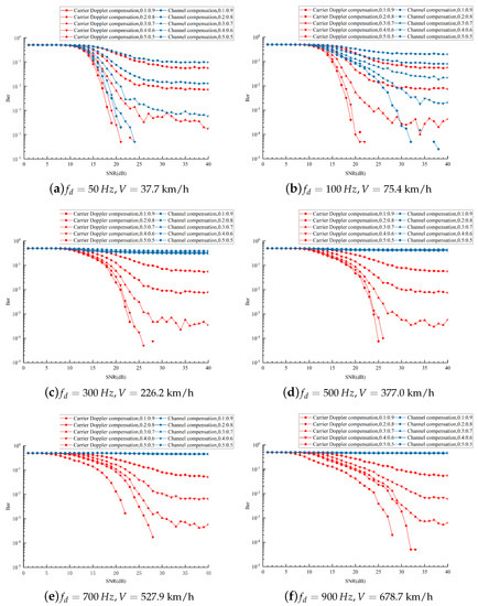
Figure 16.
BER of the composite signal under different circumstances.
As seen from Figure 16a,b, channel compensation is still effective at low speeds, and a significant effect is observed for the composite signal with a power ratio of 0.1:0.9. Thus, we take the composite signal with a power ratio of 0.1:0.9 as an example for analysis.
As shown in Table 2, the BER of the composite signal with carrier Doppler compensation is almost two orders of magnitude lower than that with channel compensation. Therefore, if high-precision Doppler frequency offset auxiliary demodulation is adopted for carrier Doppler compensation, then the BER is significantly decreased.
Table 2.
Performance comparison of carrier Doppler compensation and channel compensation at different speeds. (: = 0.1:0.9; “Yes” indicates carrier Doppler compensation, “No” indicates channel compensation).
As seen from Figure 16c–f and Table 2, as the speed of the UAVs gradually increases, the BER with channel compensation becomes approximately equal to 0.5. However, the BER with carrier Doppler compensation remains below . This means that channel compensation is no longer effective for the demodulation of the composite signal in a highly mobile environment. It also proves that carrier Doppler compensation can reduce the influence of the Doppler frequency offset on the composite signal and improve the communication performance.
Furthermore, the BERs under different power ratios are compared in this paper. Our graphs demonstrate that with a decrease in the power ratio, the BER is reduced and the communication performance is improved. The reason is that the proportion of the OFDM signal increases and the impact of noise interference decreases.
4.6. Actual Environment Simulation
In this paper, a simple UAV networking model is constructed, including a ground station node and four UAV nodes. The structure diagram of the UAV networking model is shown in Figure 17. The UAV nodes B and D cannot communicate with the ground station directly; however, they can communicate with the ground station via UAV nodes A and C indirectly. The actual scenario parameters are as follows: flight height: 1–2 km; flight speed: 80–150 km/h; distance of communication at inter-UAV: 1–5 km; distance of communication between UAV and ground station: 30–50 km; operation frequency: 5 GHz.
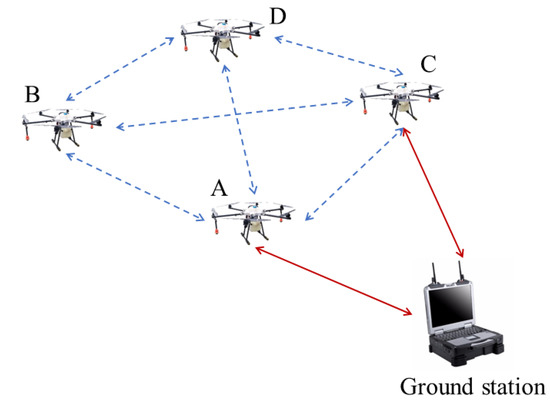
Figure 17.
The structure diagram of the UAV networking model (The UAV nodes A, B, C, D represent the four UAVs in the UAV networking model, respectively. The UAV nodes A and C can communicate with the ground station and other UAV nodes, the UAV nodes B and D cannot communicate with the ground station).
According to the actual scenario parameters, the UAV node A is simulated and analyzed. A comparison of the actual flight trajectory and the measured trajectory is shown in Figure 18. The ranging error is shown in Figure 19. Thus, the accuracy of the range error is controlled within 0.01 m. The flight speed of UAV node A is shown in Figure 20, where the max Doppler frequency offset is 630 Hz. The approach proposed in this paper can achieve a BER of communication below .
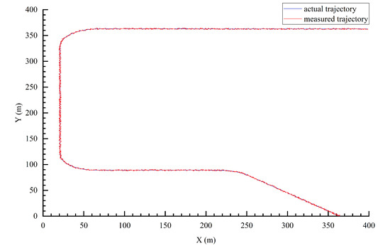
Figure 18.
Comparison of the actual flight trajectory and the measured trajectory.
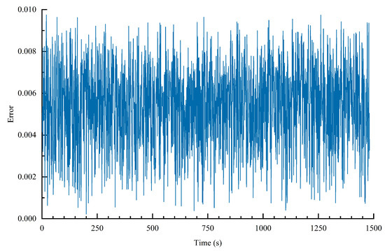
Figure 19.
Range error under an actual environment.
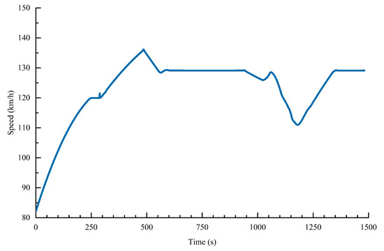
Figure 20.
Flight speeds of the UAV node A.
5. Discussion
The above simulations and analyses show the following:
- The OFDM+BOC composite signal proposed in this paper can be used to perform high-speed communication and high-precision measurement at the same frequency. High data transmission is achieved by means of OFDM modulation, and high-precision measurement is achieved by means of BOC modulation.
- Based on the properties of BOC and OFDM signals, we present a reception process for the composite signal, including acquisition, tracking and demodulation. In the demodulation stage, we adopt the high-precision Doppler frequency offset tracked by the BOC signal to assist in the demodulation of the OFDM signal. Thus, the influence of the Doppler frequency offset on the OFDM signal is significantly reduced, and the communication performance is improved.
- The acquisition and tracking performance under different conditions is simulated. The results suggest that the acquisition and tracking performance for the BOC signal is not affected by the power ratios when . Moreover, a significant improvement in the measurement accuracy is achieved.
- Furthermore, the high-precision Doppler frequency offset tracked by the BOC signal is adopted for carrier Doppler compensation to assist in the demodulation of the OFDM signal. We compare the communication performance with carrier Doppler compensation to that with channel compensation. In a low-speed mobile environment, the BER of the composite signal with carrier Doppler compensation is almost two orders of magnitude lower than that with channel compensation. In a high-speed mobile environment, the composite signal can no longer be correctly demodulated with only channel compensation, whereas the BER of the composite signal with carrier Doppler compensation is still below . This proves that the carrier Doppler compensation method proposed in this paper can greatly reduce the impact of the Doppler frequency offset on OFDM signal and improve the communication performance of UAVs in high-speed mobile environments.
6. Conclusions
The focus of this paper is to realize high-precision measurement and low-BER communication under a Doppler frequency offset environment. We propose an integrated communication and measurement system with BOC-assisted OFDM under a Doppler frequency offset environment. The transmitter utilizes the orthogonality of the OFDM subcarriers and the spectral characteristics of the BOC signal to combine OFDM modulation with BOC modulation to produce an OFDM+BOC composite signal through power control. Moreover, the receiver adopts the high-precision Doppler frequency offset tracked by the BOC signal to assist in the demodulation of the OFDM signal. The results demonstrate that a significant improvement in the measurement accuracy is achieved. The ranging error is below , and the Doppler frequency error is below 2 Hz. Compared with channel compensation, the BER of the composite signal with carrier Doppler compensation is lower by at least two orders of magnitude. Therefore, carrier Doppler compensation greatly decreases the influence of the Doppler frequency offset on the OFDM signal and improves the communication performance.
Author Contributions
Conceptualization, X.L. and L.X.; Data curation, X.Z.; Formal analysis, X.Z.; Investigation, L.X.; Methodology, X.Z.; Resources, X.Z.; Software, X.Z.; Validation, X.L. and X.Z.; Writing—original draft, X.Z.; Writing—review and editing, X.L. and X.Z. All authors have read and agreed to the published version of the manuscript.
Funding
This work was supported by the National Key R&D Program of China (No. 2021YFB3900300) and the Fundamental Research Funds for the Central Universities (No. 2022CDJKYJH036).
Institutional Review Board Statement
Not applicable.
Informed Consent Statement
Not applicable.
Data Availability Statement
Not applicable.
Conflicts of Interest
The authors declare no conflict of interest.
Abbreviations
The following abbreviations are used in this manuscript:
| UAV | Unmanned Aerial Vehicle |
| OFDM | Orthogonal Frequency Division Multiplexing |
| TC-OFDM | Time and Code Division-Orthogonal Frequency Division Multiplexing |
| PHY | Physical Layer |
| MB-OFDM | Multiband Orthogonal Frequency Division Multiplexing |
| TDOA | Time Difference of Arrival |
| BPSK | Binary Phase Shift Keying |
| BOC | Binary Offset Carrier |
| GPS | Global Positioning System |
| BDS | Beidou Navigation System |
| CNR | Carrier to Noise Ratio |
| S/P | Serial to Parallel |
| IFFT | Inverse Fast Fourier Transform |
| QPSK | Quadrature Phase Shift Keying |
| FFT | Fast Fourier Transform |
| P/S | Parallel to Serial |
| BER | Bit Error Rate |
| SPLL | Subcarrier Phase Locked Loop |
| NCO | Numerically Controlled Oscillator |
| FLL | Frequency-Locked Loop |
| PLL | Phase-Locked Loop |
| DLL | Delay-locked Loop |
| LS | Least Squares |
| AWGN | Additive White Gaussian Noise |
| SNR | Signal-to-Noise Ratio |
| PAPR | Peak-to-Average Power Ratio |
| CCDF | Complementary Cumulative Distribution Function |
References
- Ye, L.; Yang, Y.; Ma, J.; Deng, L.; Li, H. A Distributed Formation Joint Network Navigation and Positioning Algorithm. Mathematics 2022, 10, 1627. [Google Scholar] [CrossRef]
- Ye, L.; Yang, Y.; Jing, X.; Ma, J.; Deng, L.; Li, H. Single-Satellite Integrated Navigation Algorithm Based on Broadband LEO Constellation Communication Links. Remote Sens. 2021, 13, 703. [Google Scholar] [CrossRef]
- Ye, L.; Yang, Y.; Jing, X.; Li, H.; Yang, H.; Xia, Y. Altimeter + INS/Giant LEO Constellation Dual-Satellite Integrated Navigation and Positioning Algorithm Based on Similar Ellipsoid Model and UKF. Remote Sens. 2021, 13, 4099. [Google Scholar] [CrossRef]
- Ye, L.; Yang, Y.; Jing, X.; Li, H.; Yang, H.; Xia, Y. Dual-Satellite Alternate Switching Ranging/INS Integrated Navigation Algorithm for Broadband LEO Constellation Independent of Altimeter and Continuous Observation. Remote Sens. 2021, 13, 3312. [Google Scholar] [CrossRef]
- Ye, L.; Gao, N.; Yang, Y.; Li, X. A High-Precision and Low-Cost Broadband LEO 3-Satellite Alternate Switching Ranging/INS Integrated Navigation and Positioning Algorithm. Drones 2022, 6, 241. [Google Scholar] [CrossRef]
- Deng, Z.; Yu, Y.; Yuan, X.; Wan, N.; Yang, L. Situation and Development Tendency of Indoor Positioning. China Commun. 2013, 10, 42–55. [Google Scholar] [CrossRef]
- Ohhikata, Y.; Kobayashi, T. Proposal for an MB-OFDM UWB System Simultaneously Undertaking Ranging and Communications. In Proceedings of the 2005 IEEE International Conference on Ultra-Wideband, Zurich, Switzerland, 5–8 September 2005; pp. 604–608. [Google Scholar] [CrossRef]
- Dun, H.; Tiberius, C.J.M.; Janssen, G.J.M. Positioning in a Multipath Channel Using OFDM Signals With Carrier Phase Tracking. IEEE Access 2020, 8, 13011–13028. [Google Scholar] [CrossRef]
- Su, J.; Su, J.; Yi, Q.; WU, C.; Hou, W. Design and performance evaluation of a novel ranging signal based on an LEO satellite communication constellation. Geo-Spat. Inf. Sci. 2022, 11, 1–18. [Google Scholar] [CrossRef]
- Piccinni, G.; Avitabile, G.; Coviello, G.; Talarico, C. Real-Time Distance Evaluation System for Wireless Localization. IEEE Trans. Circuits Syst. I Regul. Pap. 2020, 67, 3320–3330. [Google Scholar] [CrossRef]
- Zhang, Z.; Kang, S.; Zhang, X. Indoor Carrier Phase Positioning Technology Based on OFDM System. Sensors 2021, 21, 6731. [Google Scholar] [CrossRef]
- Ma, J.; Yang, Y.; Li, H.; Li, J. FH-BOC: Generalized low-ambiguity anti-interference spread spectrum modulation based on frequency-hopping binary offset carrier. GPS Solut. 2020, 24, 70. [Google Scholar] [CrossRef]
- He, T.; Ma, Z. Proposed OFDM Modulation for Future Generations of GNSS Signal System. J. Navig. 2016, 69, 971–990. [Google Scholar] [CrossRef][Green Version]
- Ma, J.; Yang, Y.; Li, H.; Li, J. Expressions for the Autocorrelation Function and Power Spectral Density of BOC Modulation Based on Convolution Operation. Math. Probl. Eng. 2020, 2020, 1–12. [Google Scholar] [CrossRef]
- Betz, J. Binary Offset Carrier Modulation for Radionavigation. Navig. J. Inst. Navig. 2001, 48, 227–246. [Google Scholar] [CrossRef]
- Luo, X.; Schaufler, S.; Branzanti, M.; Chen, J. Assessing the benefits of Galileo to high-precision GNSS positioning-RTK, PPP and post-processing. ScienceDirect 2021, 12, 4916–4931. [Google Scholar] [CrossRef]
- Betz, J. The Offset Carrier Modulation for GPS Modernization. In Proceedings of the 1999 National Technical Meeting of the Institute of Navigation, San Diego, CA, USA, 25–27 January 1999; pp. 639–648. [Google Scholar]
- Kaiser, S.; Christianson, A.; Narayanan, M. Multistatic Doppler Estimation Using Global Positioning System Passive Coherent Location. IEEE Trans. Aerosp. Electron. Syst. 2019, 55, 2978–2991. [Google Scholar] [CrossRef]
- Lu, J.; Guo, X.; Su, C. Global capabilities of BeiDou Navigation Satellite System. Satell. Navig. 2020, 1, 1–5. [Google Scholar] [CrossRef]
- Xue, L.; Li, X.; Wu, W.; Dong, J. Multifunctional Signal Design for Measurement, Navigation and Communication Based on BOC and BPSK Modulation. Remote Sens. 2022, 14, 1653. [Google Scholar] [CrossRef]
- Wang, X.; Yang, Y.; Deng, L.; Ye, L.; Li, Z.; Xiao, Y.; Dong, W. Design and Performance Analysis of Navigation Signal Based on OFDM. Appl. Sci. 2022, 12, 9486. [Google Scholar] [CrossRef]
- Nguyen, V.; Thi, H.; Nguyen, Q.; Nguyen, T. Low Complexity Non-Uniform FFT for Doppler Compensation in OFDM-Based Underwater Acoustic Communication Systems. IEEE Access 2022, 10, 82788–82798. [Google Scholar] [CrossRef]
- Han, Q.; Zhu, K.; Hu, C.; Zhao, H.; Wu, S.; Fu, Y. BOC Signal Acquisition Algorithm Based on Similar Enfoldment. Int. J. Aerosp. Eng. 2020, 2020, 1–19. [Google Scholar] [CrossRef]
- Wang, E.; Zhao, H.; Lin, D.; Wang, J.; Liu, M. An improved method for eliminating deputy peak of BOC navigation signal. IEICE Commun. Express 2022, 11, 589–595. [Google Scholar] [CrossRef]
- Xiong, X. Signal Modulation System Analysis of Acquisition and Tracking under High Dynamic Conditions. In Proceedings of the 2019 IEEE 3rd Information Technology, Networking, Electronic and Automation Control Conference (ITNEC), Chengdu, China, 15–17 March 2019; pp. 510–513. [Google Scholar] [CrossRef]
- Chen, L.; Zhao, W.; Xie, X.; Zhao, D.; Huang, S. Harmonic Phasor Estimation Based on Frequency-Domain Sampling Theorem. IEEE Trans. Instrum. Meas. 2020, 70, 1–10. [Google Scholar] [CrossRef]
- Ma, J.; Yang, Y. A Generalized Anti-Interference Low-Ambiguity Dual-Frequency Multiplexing Modulation Based on the Frequency-Hopping Technique. IEEE Access 2020, 8, 95288–95300. [Google Scholar] [CrossRef]
- Tang, P.; Li, X.; Wang, S.; Wang, K. A Low Complexity Algorithm for Code Doppler Compensation Using FFT-Based Parallel Acquisition Architecture. In Proceedings of the 9th China Satellite Navigation Conference (CSNC)—Location, Time of Augmentation, Harbin, China, 23–25 May 2018; pp. 355–364. [Google Scholar] [CrossRef]
- Li, T.; Tang, Z.; Wei, J.; Zhou, Z.; Wang, B. Unambiguous Tracking Technique Based on Combined Correlation Functions for Sine BOC Signals. J. Navig. 2019, 72, 140–154. [Google Scholar] [CrossRef]
- Ji, Y.; Chen, X.; Fu, Q.; Sun, X.; Zhen, W. Reconstruction of sub cross-correlation cancellation technique for unambiguous acquisition of BOC(kn, n) signals. J. Syst. Eng. Electron. 2019, 30, 852–860. [Google Scholar] [CrossRef]
- Yang, D.; Rao, Y.; Shi, H.; Lu, X.; Kang, L.; Wang, X.; He, C.; Wang, M. Quality Assessment of Galileo E1A Signal. In Proceedings of the 10th China Satellite Navigation Conference (CSNC), Beijing, China, 22–25 May 2019; pp. 410–420. [Google Scholar] [CrossRef]
- Chen, Y.; Wang, X.; Chen, X.; Li, S. A Novel Combined Control Loop Based on FLL-Assisted-PLL for Highly Dynamic Tracking. In Proceedings of the 2021 International Wireless Communications and Mobile Computing (IWCMC), Harbin, China, 28 June–2 July 2021; pp. 1742–1747. [Google Scholar] [CrossRef]
- Li, W.; Qu, D.; Jiang, T. An Efficient Preamble Design Based on CombType Pilots for Channel Estimation in FBMC/OQAM Systems. IEEE Access 2018, 6, 64698–64707. [Google Scholar] [CrossRef]
- Xu, P.; Jia, Y. SNR improvement based on piecewise linear interpolation. J. Electr. Eng. 2021, 72, 348–351. [Google Scholar] [CrossRef]
- Rougerie, S.; Deloues, T.; Israel, J. A New Doppler model for LMS Channel. In Proceedings of the 2019 13th European Conference on Antennas and Propagation (EuCAP), Krakow, Poland, 31 March–5 April 2019; pp. 1–5. [Google Scholar]


Disclaimer/Publisher’s Note: The statements, opinions and data contained in all publications are solely those of the individual author(s) and contributor(s) and not of MDPI and/or the editor(s). MDPI and/or the editor(s) disclaim responsibility for any injury to people or property resulting from any ideas, methods, instructions or products referred to in the content. |
© 2022 by the authors. Licensee MDPI, Basel, Switzerland. This article is an open access article distributed under the terms and conditions of the Creative Commons Attribution (CC BY) license (https://creativecommons.org/licenses/by/4.0/).