Abstract
“HAPA” stands for High-Authority Piezoelectric Actuator, which describes high-performance piezoelectric actuators of large stroke and blocking force. “HAPAs” are made possible by high-bending-stiffness connectors that connect multiple units of piezoceramic stacks into a 2-level actuation structure. Present HAPA actuators are fitted with commercial piezoceramic stacks. For instance, a “HAPA-(2+2)” comprises 4 lead zirconate titanate (PZT) stacks, 2 in the upper level with displacement projecting upward and 2 in the lower level with displacement projecting downward. They not only double the axial displacement of individual stacks with only fractional increase in device length but also are of 1.5× to 3× larger blocking force depending on the actual design. “FTA” stands for Flextensional Actuator, in which the horizontal extensional displacement of PZT stacks is amplified to yield much larger contractional vertical displacement via a diamond-shaped elastic frame structure. A range of new FTAs has been developed by us using single or multiple units of PZT stacks, of which the performances are described in this work. “HD-FTA” stands for HAPA-Driven Flextensional Actuator, in which HAPA piezoelectric actuators are used as the motor section to drive diamond-shaped elastic members of various designs for further displacement amplification. Several HD-FTAs, driven by a HAPA-(2+2) actuator, have been developed. Compared with standard FTAs of comparable stroke, HD-FTAs display a higher working load but of smaller overall length. “HAPA”, “FTA”, and “HD-FTA” piezoelectric actuators find applications when a smaller actuator length is advantageous in addition to the required moderate-to-large displacement and working load.
1. Introduction
Piezoelectric stack actuators, made by bonding tens to hundreds of thin thickness-poled piezoceramic plates into a bar-like construction, are extensively used today in micro-/nano-positioning and motion control in precision instrument and machinery. They are of large blocking force but limited axial displacement, of >500 N and a few to tens of µm, respectively [1]. To increase the axial displacement of piezoelectric stacks, various amplification mechanisms had been devised, such as the lever-arm, flextensional, and telescopic approaches [2,3,4,5,6,7]. In doing so, however, the blocking force of the resultant device is reduced significantly.
In this work, three new types of piezoelectric actuators are described which not only have amplified axial displacement but also maintain moderate-to-large blocking force including twice to thrice that of individual stack actuator.
2. High-Authority Piezoelectric Actuator (HAPA)
High-Authority Piezoelectric Actuator (HAPA) is made possible by a patented high-bending-stiffness connector (HBSC) [8], which connects multiple units of piezoelectric stack into a 2-level actuation configuration. This can be visualized from the illustration shown in Figure 1. Depending on the type of HBSC used, HAPA actuators may be further divided into HAPA-(1+2), HAPA-(2+2) and HPAP-(3+3), where the numerals “i” and ‘j” in the symbol (i+j) denote the number of upward projecting stacks and that of the downward projecting stacks, respectively. For the HAPA actuators described in this work, the HBSC is made of an aluminum alloy (AA6061) and the piezoceramic stacks used are NEC-Tokin stack actuator (model no. AE0505D44H40DF), of 5 × 5 mm2 in foot-print and 40 mm in length. Various designs of the end caps are available including solid designs and those with a through or threaded central hole for preloading and/or mounting purposes [9,10].

Figure 1.
(a) Perspective and sectional views of a high-bending-stiffness connector (HBSC) showing the configurations of deep recesses for housing piezoelectric stacks and (b) a high-authority piezoelectric actuator (HAPA)-(2+2) made from it by bonding 4 stacks at the base of respective recesses in a 2-up-and-2-down configuration and topped up with end caps at both ends. The wirings are not shown for clarity’s sake.
Figure 2 shows the performance characteristics of HAPA actuators fabricated (see Reference [9] for a detailed description of the performance evaluation of HAPA actuators). As shown, it has nearly twice the axial displacement of individual stacks which make up the HAPA and 1.5× to 3× the blocking force depending on its actual construction. Unlike most displacement amplified mechanisms via which the blocking force of the resultant device is decreased accordingly, HAPA piezoelectric actuators thus not only double the axial displacement but also multiply the device blocking force. Furthermore, its overall length is only a fraction longer than the length of individual stacks despite having a larger foot-print. For instance, a HAPA-(2+2) actuator measures about 25 mm in diameter and 60 mm in length, including specially designed end-caps. It has a stroke of about 85 µm and 1700 N in blocking force @150V. More about different types of HAPA actuator and end-cap designs can be found in Reference [10].
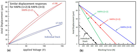
Figure 2.
(a) Displacement-versus-voltage curves and (b) displacement versus axial compressive load plots of HAPA actuators. The intercepts at the abscissa of the various curves in (b) give the blocking forces of respective HAPAs.
Table 1 compares the performance of HAPA-(2+2) with conventional amplified piezoelectric actuators of comparable stroke including lever-arm, flextensional, and telescopic. It is evident that, compared with individual stacks, while the blocking force is decreased significantly with conventional amplified approaches, this is not so for HAPA. In fact, as multiple stacks are used in HAPA, its blocking force is 1.5× to 3× that of individual stacks. Thus, in addition to being stand-alone actuators, HAPAs can be used as the motor section of other amplified designs, leading to further enhancement in stroke of the resultant device. As will be shown below, HAPA driven flextensional actuators (HD-FTA) of various designs have also been successful developed in the present work.

Table 1.
Performance comparison of HAPA, lever-arm, flextensional, and telescopic actuators.
3. Flextensional Actuator
Flextensional Actuators (FTA) have been widely used in the industry, notably when large displacement with low-to-medium payload is required (payload or maximum working load is used here because flextensional actuators contract in the active direction instead when a positive polarity voltage is applied to the stack actuator, hence making the definition of blocking force invalid). In such a design, a diamond-shaped elastic frame structure is employed to amplify the horizontal extensional displacement of PZT stacks into much larger contractional displacement in the vertical direction. This allows for a compromise, effectively converting the high blocking force and low displacement of a piezoceramic stack into a device of moderate blocking force and moderate-to-large displacement. In conventional FTAs, the motor section is made of one piezoceramic stack, typically of a square cross-section.
A range of new FTAs has been developed by us using one, two, or four units of identical PZT stack as the motor section, which offers flexibility in design and device performance. For instance, in one design, as shown in Figure 3a, two stacks of 5 × 5 mm2 cross-section are placed vertically with respect to one another. This results in a “slim FTA” of only 5 mm in depth but of improved height displacement and maximum working load allowed. When four 5 × 5 mm2 cross-sectioned stacks are used, they are arranged in a 2 × 2 square matrix manner, producing a performance equivalent to that driven by a single 10 × 10 mm2 cross-sectioned stack.
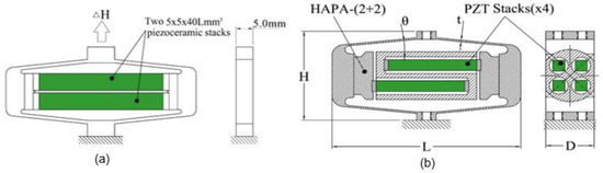
Figure 3.
Schematics showing the constructions of (a) “Slim flextensional actuator (Slim-FTA)” and (b) HAPA-Driven FTAs.
4. HAPA-Driven Flextensional Actuator (HD-FTA)
In addition to conventional FTA, new high-performance FTAs, of which the motor section is made of a HAPA-(2+2) actuator containing 4 identical stacks in a 2-up-and-2-down configuration as described in Section 2 above, have also been developed. A schematic of the construction of a HD-FTA is provided in Figure 3b. This is to take advantage of the much higher axial displacement and blocking force displayed by the HAPA-(2+2), while its overall length is only fractionally longer than an individual stack.
With the driving element pre-selected, the design optimization involves choosing a flextensional (FT) frame of the correct length (L), depth (or thickness, D), and height (H), and the inclined angle (θ) and the thickness (t) of its 4 flexural arms (see Figure 3b), such that both the height displacement (∆H) and the maximum working load allowed of the resultant device meet the specified requirements. In the present work, the FT frame is made of martensite stainless steel (SS440C).
In addition to optimizing the various parameters of the FT frame to meet the displacement and working load requirements, another key design consideration is that the FT frame must have the correct elastic stiffness and the initial pre-load level between the PZT stack or HAPA and the FT frame must be just right. This is because too high initial preload level and frame stiffness would exert exceedingly large compressive stress on to the stacks, which increases further when the stacks extend under the applied voltage. This, in turn, will reduce the attainable displacement of the stacks and degrade the overall performance of the resultant actuator (i.e., a smaller ∆H will result) and, hence, is uncalled for. On the other hand, when the initial preload is insufficient and/or the FT frame is not stiff enough, the FT frame may expand too much in its length direction when its height direction is subject to sufficiently high payload. This, in turn, would place the piezoceramic in the stacks and the various joints in the device in tension, which is highly undesirable. In the worst scenario, the joints may break off and the stacks would become loose in the device.
All these can be carefully modeled and avoided in the design stage while one attempts to maximize either the height displacement (∆H) and/or the working load of the FTA and HD-FTA when the other parameters are pre-set. An ATILA computer simulation software was used in this work in the modeling.
Another performance indicator of an FTA is its resonance frequencies, both in free-free and blocked-free end conditions. Both resonance frequencies can be obtained from the computer simulation by assigning appropriate boundary conditions to the device and by running the simulation in dynamic analysis mode.
Based on the simulation results, a range of FTAs of conventional design and 4 different types of HD-FTAs has been fabricated and evaluated. The performance of selected FTAs and HD-FTAs are provided in Table 2. In the table, each actuator is denoted with two numbers, e.g., FTA-700-100 and HD-FTA-450-200, etc., where the first numeral denotes the height displacement (∆H) at 150 V in µm and the second numeral the maximum working load allowed in N. The overall dimensions of the resultant devices vary from 56(L) × 5(D) × 25.4(H) mm for Slim-FTAs to 78(L) × 20(D) × 43(H) mm for HD-FTAs, where H is the height of the device which is also the excitation direction.
Table 2.
Measured performance of FTAs and HAPA driven flextensional actuators (HD-FTAs) developed in the present work.
Prototypes of selected designs of FTA and HD-FTA were fabricated. Both the stack or HAPA and the FT frame were assembled with care by first compressing the frame in its height (H) direction with a sufficiently high pre-load to expand its length dimension sufficiently such that the stack or HAPA-(2+2) actuator can be inserted inside the frame interior with relative ease. After releasing the pre-load to allow the frame to clamp onto the stack or HAPA via the pre-set interference fit, the assembly was tested to ensure that the stack or HAPA remained firmly in place when a working load higher than the designed maximum load was applied onto the frame. Then, the frame was similarly expanded again and the stack or HAPA was taken out to enable the epoxy adhesive to be applied onto both ends before again inserting it back and carefully positioning it inside the FT frame. Finally, the load applied onto the FT frame was released and the epoxy joints were allowed to set to make the resultant device. Pictures of a slim FTA and one of the HD-FTAs fabricated are provided in Figure 4.
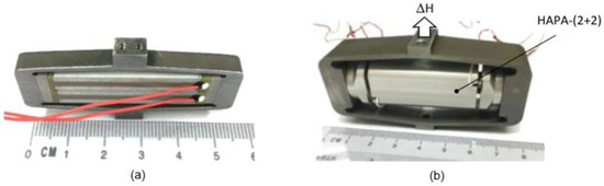
Figure 4.
Pictures of (a) a Slim FTA and (b) a HD-FTA fabricated.
The various FTAs and HD-FTAs were evaluated by measuring their height displacement (∆H) as a function of the applied voltage initially under the load-free condition and subsequently under increasing working loads up to the maximum load allowed. The details of the test set-up used can be found in Reference [9], including the working load placement arrangement. Selected results are shown in Figure 5a–d. The obtained ∆H at the maximum applied voltage of 150 V under no-load condition and under the maximum working load allowed agree reasonably well with our computer simulation results. These results are compiled in Table 2 for easy reference.
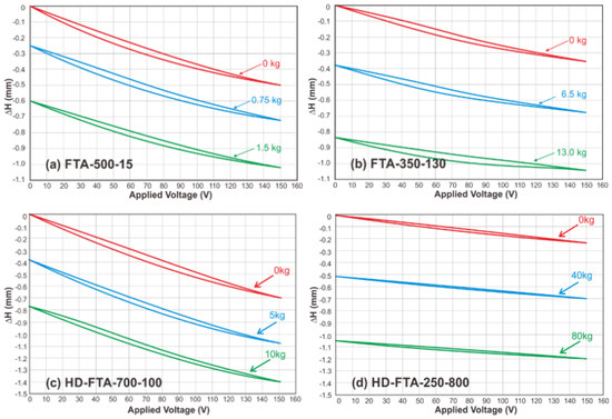
Figure 5.
Height displacement (∆H) versus voltage responses under different loads for (a) FTA-500-15, (b) FTA-350-130, (c) HD-FTA-700-100, and (d) HD-FTA-250-800.
Compared with conventional FTA designs, HD-FTAs developed in the present work display comparatively large height displacement, comparable or higher working loads, and smaller overall length. However, they have smaller resonance frequencies notably under blocked-free end conditions, due to the extra mass of the aluminum alloy HBSC in the HAPA actuator.
5. Conclusions
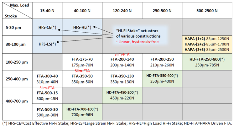
Three new types of piezoelectric actuators are described in this work: High-authority piezoelectric actuator, or HAPA, made possible by means of the high-bending stiffness connector (HBSC), which connects multiple units of piezoceramic stacks in a 2-level actuation configuration, displays about twice the displacement of individual stacks and 1.5× to 3× the blocking force depending on the actual construction. MMT flextensional actuators (FTA) are driven by one to four identical PZT stacks, offering a wide range of performance characteristics. FTAs driven by a HAPA-(2+2) actuator (HD-FTA) have also been successfully developed, which provide large height displacements for moderate to high payloads but of smaller overall length. Table 3 compiles the performance of these new types of piezoelectric actuators for easy reference. Also included in this table are Hi-Fi Stake single crystal piezoelectric actuators [14,15], of which the displacement responses are linear with negligible strain hysteresis when used under specified conditions. “HAPA”, “FTA”, and “HD-FTA” piezoelectric actuators find applications when a smaller actuator length is advantageous in addition to the required moderate-to-large displacement and working load.
Table 3.
Stroke and blocking force (or max. working load) of MMT piezoelectric actuators of various designs.
Author Contributions
D.-H.L., Y.X., J.-H.K., and F.-C.L. are all involved in the fabrication and evaluation of various actuators described in this work. L.-C.L. is the project manager. The simulation work was performed by Y.X. The paper was written jointly by D.-H.L. and L.-C.L. All authors have read and agreed to the published version of the manuscript.
Acknowledgments
The authors would like to thank the staff of MMT for the technical help rendered in the present work.
Conflicts of Interest
The authors declare no conflict of interest.
Abbreviations
The following abbreviations are used in this manuscript:
| MMT | Microfine Materials Technologies Pte Ltd. |
| HAPA | High-Authority Piezoelectric Actuator |
| HBSC | High Bending Stiffness Connector |
| PZT | Lead Zirconate Titanate |
| FTA | Flextensional Actuator |
| FT frame | Flextensional frame |
| HD-FTA | HAPA-Driven Flextensional Actuator |
References
- Niezercki, C.; Beri, D.; Balashrishnan, S.; Moskalik, A. Piezoelectric actuator: State of the art. Shock Vib. Dig. 2001, 33, 269–280. [Google Scholar] [CrossRef]
- Toulis, E.J. Flexural-Extensional Electromechanical Transducer. U.S. Patent No. US3277433, 4 October 1966. [Google Scholar]
- Royster, L.H. The flextensional concept: A new approach to the design of underwater acoustic transducers. Appl. Acoust. 1970, 3, 117–126. [Google Scholar] [CrossRef]
- Uchikawa, T. Mechanical Amplification Mechanism Combined with Piezoelectric elements. U.S. Patent No. US 4,570,095, 11 February 1986. [Google Scholar]
- Asano, H. Piezoelectric Actuator. U.S. Patent No. US4783610A, 8 November 1988. [Google Scholar]
- Wu, C.C.M.; Lewis, D.; Kahn, M.; Chase, M. High authority telescopic actuators. Proc. SPIE 1999, 3674, 212–219. [Google Scholar]
- Brei, D.E.; Hallovan, J. Solid State High Authority Telescoping Actuators. Available online: http://www.dtic.mil/dtic/tr//fulltext/u2/a400693.pdf (accessed on 28 December 2020).
- Lim, L.C.; Huang, Y.; Xia, Y.X.; Lin, D.H. Displacement Connectors of High Bending Stiffness and Piezoelectric Actuators Made of Such. WIPO/PCT Patent No. WO/2017 17629 A1, 12 October 2017. [Google Scholar]
- Huang, Y.; Xia, Y.X.; Lin, D.H.; Lim, L.C. High-bending-stiffness-connector (HBSC) and high-authority piezoelectric actuator (HAPA) made of such. Actuators 2018, 7, 61. [Google Scholar] [CrossRef]
- Available online: http://www.microfine-piezo.com/files/HAPA-4page.pdf (accessed on 28 December 2020).
- P.I. P-601 PiezoMove Linear Actuator with Guides. Available online: http://www.physikinstrumente.com/en/products/piezoceramic-acutators/liner-actuators/p-601-piezomove-flexture-guided-linear-actuator-202600/ (accessed on 28 December 2020).
- Cedrat Technologies, Amplified Piezoelectric Actuators. Available online: http://www.cedrat-technologies.com/en/products/actuators/apa.html (accessed on 28 December 2020).
- Alexander, P.W.; Brei, D. Piezoceramic telescopic actuator: Quasi-state experimental characterization. J. Intell. Mater. Syst. Struct. 2003, 14, 643–655. [Google Scholar] [CrossRef]
- Huang, Y.; Zhang, S.; Wang, P.; Xia, Y.X.; Lin, D.H.; Yao, K.; Lim, L.C. Hi-Fi Stake piezo single crystal actuator. Actuators 2018, 7, 60. [Google Scholar] [CrossRef]
- Lim, F.C.; Lin, D.H.; Xia, Y.X.; Koh, J.H.; Lim, L.C. “Hi-Fi Stake” Piezoelectric Actuators and New Developments. Available online: https://sciforum.net/paper/view/conference/8506 (accessed on 28 December 2020).
Publisher’s Note: MDPI stays neutral with regard to jurisdictional claims in published maps and institutional affiliations. |
© 2021 by the authors. Licensee MDPI, Basel, Switzerland. This article is an open access article distributed under the terms and conditions of the Creative Commons Attribution (CC BY) license (https://creativecommons.org/licenses/by/4.0/).