Abstract
Recently, the demand for a bio-absorbable coronary stent to promote recovery after an operation has increased. An option for such a stent is one made of a magnesium alloy, which has biodegradable properties. However, magnesium alloys have lower rigidity and lower ductility than other metals; as such, an appropriate stent structure is required to ensure radial rigidity. In this study, design parameters for an AZ31 magnesium alloy stent with sufficient radial rigidity were investigated. The necessary radial rigidity was determined by comparison tests against commercially available stents. The design parameters of the cell struts were selected and the optimum values to achieve high radial rigidity were investigated by means of elastic–plastic finite element analysis. Finally, a trial model stent based on the optimized design parameters was produced. It was confirmed that the model had sufficient radial rigidity, with no fracturing evident during crimping and expansion processes.
1. Introduction
A balloon-expandable stent for a coronary artery is a small medical device that is implanted into a stenosis to allow blood flow. The stent is first crimped onto a balloon at the tip of a catheter, delivered to the stenosis through blood vessels, and then expanded by inflating the balloon. A sufficient radial rigidity is therefore essential after the stenting process to keep the blood vessel open.
Coronary stents are made of biocompatible (nontoxic) metals, such as cobalt–chromium alloy (CoCr), platinum–chromium alloy (PtCr), cobalt–nickel alloy (CoNi), or stainless steel (SUS). In recent years, the demand for a stent with bio-absorbable properties to promote recovery after an operation has increased. A magnesium alloy stent is a promising choice because of its biodegradable properties and biocompatibility. However, in general, magnesium alloys have several disadvantages in relation to their mechanical properties, e.g., lower rigidity and inferior ductility compared with the metals used for ordinary stents. Therefore, an appropriate stent structure design is required to ensure radial rigidity. Although there are numerous papers on the mechanical properties of stent structure [1,2,3], only a few [4,5,6] were found on the design parameters of balloon-expandable stents. In addition, there are no reports relating to the design of a magnesium alloy stent.
In order to actualize a bio-absorbable magnesium alloy stent, the present study consisted of the following steps: (1) clarify the necessary radial rigidity; (2) evaluate the mechanical properties of the magnesium alloy material; (3) select and evaluate the design parameters; and (4) produce a trial model stent to confirm its radial rigidity. The necessary radial rigidity was determined by comparison with commercially available stents in radial force tests. The mechanical properties of a magnesium alloy thin-walled tube were evaluated in uniaxial tensile tests. Based on the obtained mechanical properties, finite element analysis was performed to determine the optimum design parameters. Finally, a magnesium alloy stent having the selected design parameters was produced and its radial rigidity was evaluated.
2. Materials and Methods
2.1. Magnesium Alloy Stent Material
The magnesium alloy, AZ31, which contains approximately 3% aluminum and 1% zinc, was selected as the stent material owing to its superior mechanical properties among the magnesium alloys. A thin-walled tube having an outer diameter of 1.8 mm and wall thickness of 150 μm was manufactured from an initial cylindrical bar by combining extrusion, drawing, and heat treatment processes.
2.2. Radial Rigidity Test of Stent
Figure 1 schematically shows the stenting process of a balloon-expandable coronary stent. The stent is first crimped onto a balloon catheter and delivered to the stenosed region through blood vessels. The stent is then expanded by inflating the balloon, which keeps the vessel open and ensures blood flow. Finally, the balloon is deflated and the catheter is removed, leaving the stent in place. Therefore, the radial rigidity of a stent should be evaluated in the expanded condition.
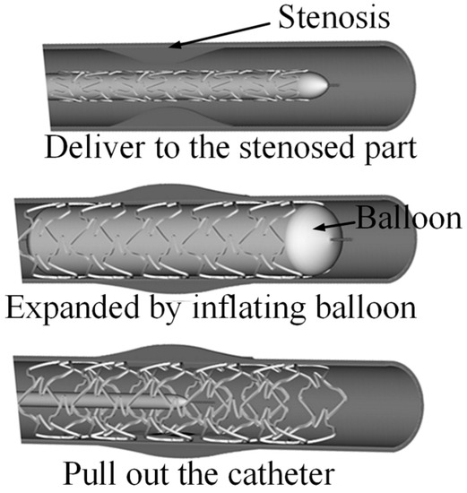
Figure 1.
Schematic showing stenting process of a balloon-expandable stent.
In this work, the radial rigidity of the stent was evaluated using a radial force tester (A Machine Solutions Company, Flagstaff, AZ, USA, RX550). The expanded stent was connected to the tester and a radial compressive force was applied to uniformly reduce the stent diameter. The variation in radial reactive force with the diameter change was recorded. An example radial force-diameter curve for the stent is shown in Figure 2. Owing to elastic deformation, the radial force increased almost linearly with diameter reduction. The radial rigidity was defined as the slope in this region of the curve. Comparative testing of the radial rigidity of commercially available stents was then performed to help identify the target radial rigidity.
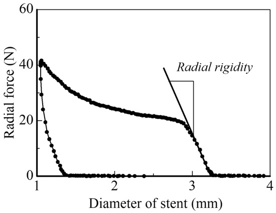
Figure 2.
An example of radial force versus diameter curve of a coronary stent.
2.3. Mechanical Property Testing of Magnesium Alloy Tube
The mechanical properties of the AZ31 magnesium alloy tube material were investigated using a uniaxial tensile test. The test was performed using a universal material tester (Baldwin Co., Daphne, AL, USA, LTB-500L-F) to obtain the stress–strain relation in the tube axial direction. The tube specimen was cut to 50 mm in length. Circular bars of 1.5 mm in diameter and 15 mm in length were inserted into both ends of the tube to prevent collapse caused by gripping. The test was conducted at a cross-head speed of 5 mm/min. The load–displacement relation was synchronously recorded. The obtained stress–strain relation was then used in finite element analysis.
2.4. Finite Element Analysis
The optimum design of the magnesium alloy coronary stent ensuring radial rigidity was investigated by elastic–plastic finite element analysis using MSC-Marc 2015. Figure 3 shows the basic stent design. The stent consists of cell and link struts, which fulfill the basic requirements for a balloon-expandable coronary artery stent: a low strut thickness of less than 120 μm and a small crossing profile diameter of less than 1.2 mm. Although it is rather common to model the whole stent structure in finite element studies [7,8,9], only the cell strut was modeled here because radial rigidity is strongly affected by cell strut dimensions. The selected design parameters for the cell strut model are shown in Figure 4, where w and h are the half-cell width and cell height, respectively; wT and wS are the strut widths of the curved portion and straight portion, respectively; rO is the outer radius of curvature of the curved portion; and lS is the length of the straight portion, which is determined once the other parameters are fixed. The model was meshed with quadratic hexahedral elements. The Young’s modulus and Poisson’s ratio were set to 45 GPa and 0.35, respectively. In the plastic deformation region, the stress–strain relation obtained by the uniaxial tensile test was used.
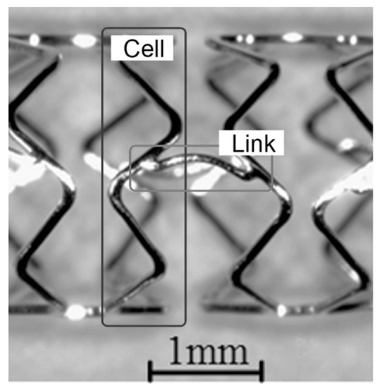
Figure 3.
Typical structure of coronary stent, consisting of cell strut and link strut.
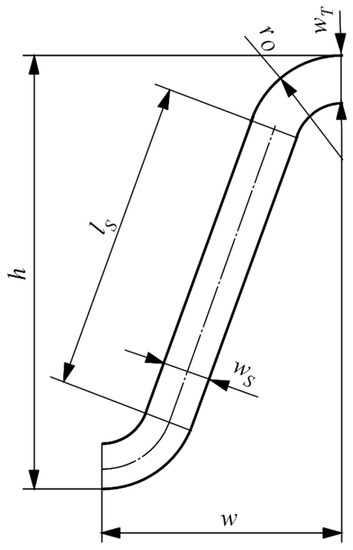
Figure 4.
Design parameters of cell strut for optimization of radial rigidity.
3. Results and Discussion
3.1. Radial Rigidity of Stents
Since there is no standard value recommended for the radial rigidity of coronary stents, radial force tests of commercially available stents were performed. Ten different coronary stents were selected and tested. The obtained radial rigidity results were plotted against the measured strut thickness, as shown in Figure 5. Although it would seem that radial rigidity should depend on the construction materials, the scattered radial rigidity data points actually imply a design dependency. The average radial rigidity was 78.9 N/mm, which was taken as the target value for the designed coronary stent.
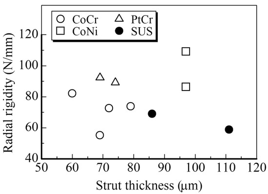
Figure 5.
Radial rigidity versus strut thickness of commercially available stents.
3.2. Tensile Stress–Strain Relation of AZ31 Magnesium Alloy Tube
The true stress–true strain relation of the AZ31 magnesium alloy circular tube, as obtained by the uniaxial tensile test, is shown in Figure 6. The test was repeated three times to check reproducibility. The profile of the stress–strain curve is somewhat similar to that of conventional metals, which obey an exponential hardening law. This implies that mechanical twinning was not noticeably activated during the tensile testing. The 0.2% proof stress was about 190 MPa and the tensile strength was about 322 MPa. The uniform elongation was about 0.17, which is much less than that of other alloys used for coronary stents.
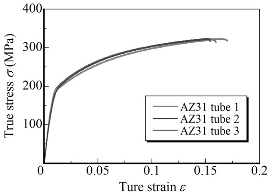
Figure 6.
Tensile true stress–true strain curve of AZ31 magnesium alloy tube.
3.3. Optimization of Stent Design
Although coronary stents of various designs have been developed by many companies, a relatively simple cell strut design (as shown in Figure 4) was selected for the magnesium alloy stent in this study. This design took into account the crossing profile of the stent when crimped onto the balloon catheter. The basic design was also line symmetrical to prevent twisting during expansion. Taking account of this symmetry, a one-twelfth stent circumference was modeled, as shown in Figure 4. The specifications required for the coronary stent are summarized in Table 1.

Table 1.
Target specification for AZ31 magnesium alloy coronary stent.
The initial width w of the half-cell strut model was determined as 0.471 mm, which was one-twelfth of the circumference of the outer diameter of the tube material (1.8 mm). The model was compressed to w = 0.283 mm, which corresponded to the crimped state (outer diameter of 1.08 mm). It was then expanded to w = 0.785 mm, which corresponded to the expanded state (outer diameter of 3 mm). Finally, the radial force increment, i.e., the reaction force increment acting against the compressive displacement in the width direction, was evaluated. The standard value and evaluation range of the design parameters are summarized in Table 2. The range was restricted according to the specifications shown in Table 1. The influence of each design parameter was investigated while maintaining the other parameters at their standard values.

Table 2.
Standard values and evaluation range of design parameters shown in Figure 4.
Figure 7 shows the influence of the various design parameters on the radial force increment and the maximum stress at the expansion. In the parameter ranges investigated, it was found that the radial force increment became larger with decreases in cell height and curvature radius and with increases in the strut width of the curved and straight portions. However, the maximum stress tended to increase with the radial force increment, which may induce fracture during expansion. In order to maximize the radial force increment while suppressing the maximum stress, the following design parameters were required: cell height h = 0.97 mm, outer radius of curvature rO = 0.223 mm, strut width of curved portion wT = 0.125 mm, and strut width of straight portion wS = 0.105 mm.
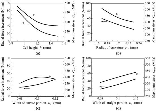
Figure 7.
Variations in radial force increment and maximum stress with (a) cell height; (b) outer curvature radius of curved portion; (c) width of curved portion; and (d) width of straight portion, as obtained by finite element analysis.
3.4. Radial Rigidity Test of the Trial Model
Based upon the investigation by the finite element analysis described above, a trial model stent was produced from the AZ31 magnesium alloy tube using a laser cutting and electro-polishing process. The development plan and a picture of the trial model are shown in Figure 8. The link struts were connected near the center of the straight portion so as to restrict length changes of the stent owing to changes in diameter during crimping and expansion. This stent had 16 cell struts in its longitudinal direction. Figure 9 shows the radial rigidity test results. The evaluated radial rigidity was 69.3 N/mm, which was not very high but was comparable to those values determined for the commercially available stents. It was confirmed that no fractures occurred during the crimping and expansion processes. These results indicate the potential for producing a bio-absorbable AZ31 magnesium alloy coronary stent having sufficient radial rigidity.
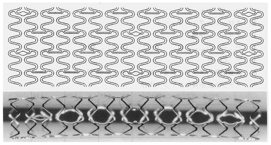
Figure 8.
Trial model of the AZ31 magnesium alloy stent produced with design parameters determined by analytical investigation.
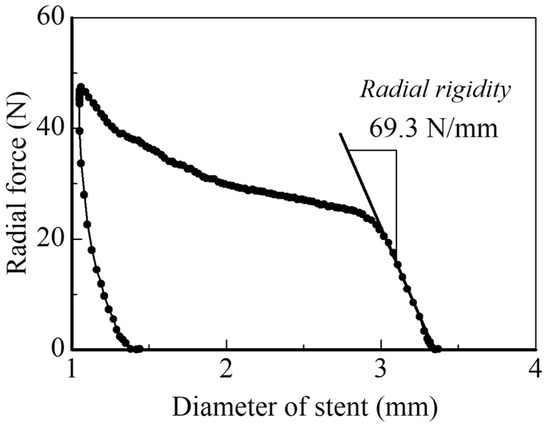
Figure 9.
Radial rigidity test of the trial model stent.
4. Summary
In order to develop a bio-absorbable magnesium alloy stent for coronary diseases, the design parameters necessary to achieve a radial rigidity comparable with that of commercially available stents were investigated. Radial force tests of commercially available coronary stents were conducted and the results revealed the necessary radial rigidity. The design parameters of the cell struts were selected to satisfy the required specifications for a balloon-expandable coronary stent. An investigation of the design parameters of the cell strut was then performed by elastic–plastic finite element analysis using the stress–strain relation obtained from a uniaxial tensile test of a thin-walled AZ31 magnesium alloy tube. Based on the results, the design parameter values to achieve sufficient radial rigidity and no fractures during the crimping and expansion processes were determined. Finally, a trial model stent based on the design parameters was manufactured, and it was confirmed that the radial rigidity of the stent was comparable to that of commercially available stents.
References
- Migliavacca, F.; Petrini, L.; Colombo, M.; Auricchio, F.; Pietrabissa, R. Mechanical behavior of coronary stents investigated through the finite element method. J. Biomech. 2002, 35, 803–811. [Google Scholar] [CrossRef]
- Weiss, S.; Meissner, A.; Fischer, A. Microstructural changes within similar coronary stents produced from two different austenitic steels. J. Mech. Behav. Biomed. Mater. 2009, 2, 210–216. [Google Scholar] [CrossRef] [PubMed]
- Grogan, J.A.; Leen, S.B.; McHugh, P.E. Comparing coronary stent material performance on a common geometric platform through simulated bench testing. J. Mech. Behav. Biomed. Mater. 2012, 12, 129–138. [Google Scholar] [CrossRef] [PubMed]
- Mori, K.; Saito, T. Effects of stent structure on stent flexibility measurements. Ann. Biomed. Eng. 2005, 33, 733–742. [Google Scholar] [CrossRef] [PubMed]
- Holzapfel, G.A.; Stadler, M. Changes in the mechanical environment of stenotic arteries during interaction with stents: Computational assessment of parametric stent designs. J. Biomech. Eng. 2005, 127, 166–180. [Google Scholar] [CrossRef] [PubMed]
- Hsiao, H.-M.; Yeh, C.-T.; Wang, C.; Chao, L.-H.; Li, D.-R. Effects of stent design on new clinical issue of longitudinal stent compression in interventional cardiology. Biomed. Microdevices 2014, 16, 599–607. [Google Scholar] [CrossRef] [PubMed]
- Petrini, L.; Migliavacca, F.; Auricchio, F.; Dubini, G. Numerical investigation of the intravascular coronary stent flexibility. J. Biomech. 2004, 37, 495–501. [Google Scholar] [CrossRef] [PubMed]
- Wu, W.; Yang, D.-Z.; Qi, M.; Wang, W.-Q. An FEA method to study flexibility of expanded coronary stents. J. Mater. Process. Technol. 2007, 184, 447–450. [Google Scholar] [CrossRef]
- Ju, F.; Xia, Z.; Sasaki, K. On the finite element modelling of balloon-expandable stents. J. Mech. Behav. Biomed. Mater. 2008, 1, 86–95. [Google Scholar] [CrossRef] [PubMed]
Publisher’s Note: MDPI stays neutral with regard to jurisdictional claims in published maps and institutional affiliations. |
© 2018 by the authors. Licensee MDPI, Basel, Switzerland. This article is an open access article distributed under the terms and conditions of the Creative Commons Attribution (CC BY) license (https://creativecommons.org/licenses/by/4.0/).