Abstract
Lithium-ion batteries form the backbone of the recent transition to electric vehicles (EVs). Due to limited capacities, costly replacements, and short lifetimes, proper control and management systems are essential for developing modern battery-powered EV systems. Brushless direct current (BLDC) motors have gained popularity in traction and industrial drive applications due to their high efficiency and long lifespan. The speed controller for the BLDC motor is a critical element in defining the system’s overall response and performance. Therefore, this paper presents a non-integer fractional-order control scheme to enhance a hybridized speed controller for BLDC motors. Unlike existing integer- and non-integer-based controllers in the literature, the new modified controller is a hybrid structure that combines the three control schemes. The proposed control is constructed using the hybrid proportional-tilt-fractional order Integrator-derivative with filter (PTFOIDN) controller. The proposed PTFOIDN controller inherently incorporates the merits of FOPI, TID, and FOPID control structures and branches within a single, hybridized structure. The proposed PTFOIDN controller features eight tunable parameters, allowing for more flexible design possibilities. Furthermore, a practical design methodology using a recent Marine Predators Algorithm (MPA) is proposed in this paper to determine the optimum set of control parameters simultaneously. Different drive cycles, comparative analysis, and operating scenarios are presented in the paper to validate the effectiveness of the new proposed PTFOID controller and MPA-based control design.
1. Introduction
1.1. Overview
Reducing greenhouse gas emissions, especially in the transportation sector, through the energy transition and associated processes, has led to rapid advances and developments in electrified and clean vehicles []. Electric vehicles (EVs) and their integration with smart grids are two crucial technologies that enable this target. The EVs offer zero-emission transportation through electric propulsion, thus reducing the environmental impact []. The wheels, drive motor, and transmission are the three fundamental parts of an electric vehicle. Motor drives consist of electric motors, power electronic converters, and controllers. Increased efficiency during regenerative braking leads to lower maintenance costs and a more reasonable overall system cost []. The vehicle’s wheels are propelled by the electric drive system, which transforms stored electrical energy into mechanical energy at different speeds. Most modern EVs utilize rechargeable lithium-ion batteries due to their high energy density, design flexibility, and outstanding electrochemical properties []. For EVs to operate effectively, the energy storage system (ESS) must have high energy and power densities, which are not typically achievable with a single energy source [,]. Batteries often have a higher energy density, but their life cycles are shorter and their specific power is lower.
Electric vehicle traction motors can generally be divided into two categories: DC motors (which include series, shunt, and compound motors) and AC motors (which include permanent magnet AC motors (PMAC)) []. DC motors can offer the advantages of a simple operation principle and straightforward torque control. However, they require more frequent maintenance due to brush wear, reduced efficiency, and decreased operating lifetime compared to AC motors. The flexibility of DC motors, combined with the increasing deployment of autonomous commercial vehicles, makes DC motors more prevalent. In contrast, AC motors are superior in efficiency, torque density, and sustained power output. Brushless DC (BLDC) motors enable one to reap the benefits of both a DC motor and an AC motor, without the brush in a brush-positional motor. The brushless aspect and reduced friction result in a more efficient, reliable, and longer-lasting motor. Traditional induction motors are expected to be replaced by BLDC motors, which are predicted to become a common power transmission method across industries by 2030. The advantages of BLDC motors in EVs and their improved effectiveness testify to their ability to revolutionize industrial applications. A BLDC-powered quarter-vehicle model that simulates the longitudinal behavior of the drive wheel is presented in []. A sensorless control method has been presented for BLDC motors in EVs, wherein eliminating sensors improves robustness, performance, and motor startup with loads. Removing sensors enhances robustness, performance, and motor starting capabilities under load. Because lithium-ion batteries are long-cycled and have high energy and power capabilities, they are often used in EVs [].
Speed control for BLDC motors is required in many industrial and automotive applications. Speed regulation strategies are developed based on particular requirements and operating conditions. The PI and ANFIS controllers were introduced by the authors in [] to manage the speed of a BLDC motor in EVs by improving transient responses and reducing steady-state error. In ref. [], the optimization of the PID controller for a DC-DC boost converter-fed BLDC motor in solar applications is presented for improving voltage stability. Ref. [] introduced a control system for BLDC motors based on a neural network fuzzy PID controller. Electric vehicle BLDC motor speed control using the tilt integral derivative (TID) controller is discussed in [] and compared to PID and PI controllers.
The controller for fractional order PID (FOPID) has become a widespread industrial standard, outperforming traditional PID controllers due to its superior performance, including enhanced robustness against system disturbances and parametric variations. An FOPID controller for direct control of BLDC motor torque and speed is presented in [,]. The authors have used several optimization-based tuning techniques to determine the controller parameters. In ref. [], the modified genetic algorithm (MGA) is presented as a way to improve the parameters of an FOPID controller for sensorless BLDC motor speed control. It proves to be an effective optimization technique for finding the optimum parameters. The artificial bee colony (ABC) technique is employed to solve complex optimization problems in the most effective manner []. PID/FOPID speed controllers have been presented for DC motor drives based on the ABC algorithm [].
Particle swarm optimization (PSO) and bacterial foraging approaches are employed to optimize the gains of a PID controller in BLDC motor speed control []. The bat algorithm is used to optimize gains for PID, fuzzy PID, and adaptive fuzzy logic controllers []. The direction of moths towards moonlight serves as the inspiration for the new metaheuristic known as the moth swarm algorithm (MSA). Preliminary evaluations alongside four alternative optimization algorithms demonstrate its efficacy in addressing nonlinear and complex problems []. The arithmetic optimization algorithm (AOA) and Harris Hawk Optimization (HHO) were combined to create the upgraded AOA-HHO optimization approach, which was presented to find the best PID controller settings. It was used for three fluid-level sequential tank systems and DC motor control, showing better performance compared with other algorithms []. In ref. [], the Western System Coordinating Council (WSCC) power system’s transient stability is enhanced by optimizing the parameters of a PID controller using the AOA method.
In ref. [], a PID controller design and implementation technique has been presented for the newly created flower pollination algorithm (FPA) to optimize the speed control of a BLDC motor. The integral square error (ISE) is minimized to perform the optimization. In the electrical machine control application, the robustness of the fractional order PID (FOPID) controller is examined in [] in comparison to the integer order PID (IOPID) controller. The FOPID controller was found to behave more robustly and be more stable than the IOPID controller. The authors of [] presented a technique for reliably assessing the FOPID controller used with a DC motor, exposing its subpar speed response properties, including rising time, peak time, and settling time. The authors of [] have suggested a novel method for fine-tuning fractional-order PI/PD controllers. In ref. [], a technique for using a step command signal to tune the FOPID controller is presented. In ref. [], an ABC algorithm-optimized FOPID controller is suggested to lower error indices (ISE, IAE, and ITAE) for a certain class of plants.
1.2. Problem Statement
Based on the above-discussed speed controllers for BLDC motors, fractional-order (FO)-based speed controllers offer higher design freedom and flexibility due to their inherent FO operators. However, the hybridization of existing controllers makes it possible to merge the best characteristics of each one. In addition, the design of sophisticated FO controllers is a critical issue compared to the possible simpler design processes of integer-order-based controllers. Existing design methods in the literature for non-integer controllers are complex and need a unified design process. Instead, metaheuristic optimizers have proven to be a suitable and efficient approach for designing complex control methods in various applications. In addition, they can provide an optimal set of parameters together, rather than optimizing parameters individually, leading to a guaranteed optimal design. The Marine Predators Algorithm (MPA) was recently developed. The MPA optimizer has proven to improve designs in several applications. This paper also presents the first application of MPA in motor speed control design.
1.3. Paper Contribution
The summarized contribution items of this paper are as follows:
- An enhanced noninteger controller is proposed in this paper by hybridizing three popular fractional-order controllers. The new proposed controller is a hybrid structure based on a proportional-tilt-fractional order integrator-derivative (PTFOID) controller.
- The proposed PTFOIDN controller inherently incorporates the merits of FOPI, TID, and FOPID control structures and branches within a single, hybridized structure. Additionally, the proposed PTFOID controller features seven tunable parameters, allowing for more flexible design possibilities.
- In this study, we present a new application of the recently developed MPA optimizer to simultaneously identify the optimal control settings.
The rest of the document is structured as follows: A comprehensive model of BLDC motors and Li-ion batteries is presented in Section 2, along with their control. The proposed PTFOID controller is presented in Section 3. The MPA and optimization methodology of the proposed PTFOID controller are given in Section 4. Several comparisons and the associated test results are shown in Section 5. The paper’s conclusions are presented in Section 6.
2. Power Stage Modeling and Control Description
The power stage is the central component of an EV drive system. To move the wheels, it must convert the electrical energy stored in the battery into mechanical motion. Accurately controlling the speed of BLDC motors in EVs depends on the proper coordination of key elements (controller, optimization strategy, feedback loop). The system modeling and the operational process components are illustrated in Figure 1. The system is powered by a lithium-ion battery, serving as its primary power source. The battery supplies a steady DC voltage needed to drive the inverter and the controller. The BLDC motor is mechanically coupled to the EV wheel, transmitting electrical input into rotational motion.
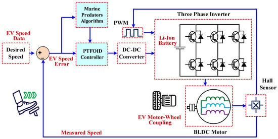
Figure 1.
Block diagram of an EV using a BLDC motor with the proposed PTFOID controller.
2.1. Lithium-Ion Battery Modeling
An effective rechargeable battery, the lithium-ion (Li-ion) battery, transports lithium ions from the anode to the cathode during discharge and back again during charging. In this study, the Thevenin-based first-order RC model was selected to represent the lithium-ion battery due to its effectiveness in balancing modeling accuracy with simulation simplicity. The mathematical model of a Li-ion battery used in EVs usually comprises the electrical behavior of the battery, taking into account its internal dynamics and nonlinearity. The equivalent circuit model of a Li-ion battery, as shown in Figure 2, consists of parallel RC networks that describe the battery’s dynamic behavior, a series resistance, and a voltage source representing the open-circuit voltage (OCV). According to Kirchhoff’s law, the current flowing through the RC network is expressed as []:
where is the parallel resistance that represents the polarization losses and is the capacitance of the RC network. The voltage at the battery terminal can be obtained by []:
where is the internal ohmic resistance of the battery, refers to the overvoltage throughout the RC network, and is the open-circuit voltage and can be described by:
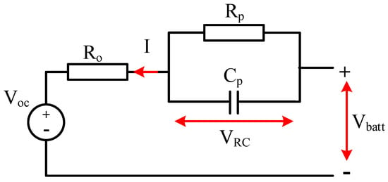
Figure 2.
First-order RC battery model.
By integrating the current provided or pulled from the battery, scaled by capacity and efficiency, the Coulomb counting approach allows one to estimate the state of charge (SoC) over time []:
where denotes the Coulombic efficiency and represents the battery capacity in Ah, is the SoC at time t, and is the SoC at the initial time. The rate of change of the open-circuit voltage as a function of time can also be expressed as:
During the constant voltage (CV) charging phase, the current is typically less than half the rated capacity of the battery . Consequently, the expression generally remains below 0.000139 in CV mode. As a result, the rate of change in the state of charge becomes negligible, allowing the assumption to remain valid during this period.
Similarly, the change in the impedance parameter can be considered insignificant during the CV charging phase, i.e.,. Furthermore, holds because the battery terminal voltage is maintained at a constant level throughout the CV period.
By differentiating the current response and substituting previous relations, the following first-order differential equation can be derived:
The analytical form of the CV charging current can be found as follows, assuming that the impedance parameters (, , ) and , , are known:
where the current seen at the start of the CV charging stage is denoted by .
2.2. BLDC Motor Model
The BLDC motor’s electrical and mechanical dynamics must be explained mathematically, allowing for the analysis and control of its performance in various applications, such as EVs in our study. The BLDC motor model is developed based on the fundamental parameters of the motor, specifically the voltage and induced current on the rotor side. For the simplification, the model typically assumes ideal operating conditions, i.e., losses such as iron and stray losses are ignored, and harmonic distortion in stator windings is disregarded.
Based on these assumptions, dynamic voltage equations for all three stator phases are derived using Kirchhoff’s voltage law. The dynamic voltage equations for each phase of the BLDC motor are given by (8), which accounts for the voltage drops across the stator resistance, the stator inductance, and the back electromotive force (back EMF). These equations are given as:
where and are the stator phase voltages, and are the phase currents, represents the stator resistance per phase, L is the stator inductance per phase, M refers to mutual inductance between different phases, and and represent the back EMFs generated in the stator windings for each of the three phases.
The total phase current in a balanced three-phase system must be zero:
The above equations can be rewritten in a compact matrix form for simulation and control systems []. The mutual inductance term M is neglected to simplify the model, as it has minimal effect in a balanced three-phase BLDC system [].
The differential in (11) describes how the phase currents , , and vary with time. These equations are obtained by substituting the phase voltage expressions and isolating the current derivatives. The time-dependent variables include the phase currents, line voltages and , and back EMFs (, , and ), all of which change dynamically according to the motor’s operating conditions and rotor position. The stator resistance and inductance are assumed to be constant parameters.
The back EMFs generated in each phase are proportional to the rotor’s electrical angular velocity and depend on the rotor position as follows:
where represents the back EMF constant, refers to the back EMF waveform, which is dependent on the angle of rotor position , and represents the electrical angular speed of the rotor. The electrical speed is related to the mechanical angular velocity by the number of pairs of poles P:
Mechanical performance-related modeling of the BLDC motor is expressed as
where represents the load torque, J denotes the mass moment of inertia, and B is the damping coefficient attributed to bearing friction, which is assumed to behave as a viscous damping type. The mechanical angular velocity is determined by solving the following differential equation:
The electromagnetic torque of the BLDC motor is proportional to the phase currents and the back EMF as expressed in (16) as follows:
The total torque is also given by:
The total electromagnetic torque applied to the motor shaft is given by:
To represent this system in state space form, we can define the state vector x and input vector u as follows []:
Thus, the state-space representation of the BLDC motor dynamics can be formulated as follows:
The mechanical speed output equation of the BLDC motor can be expressed as follows:
The system matrices presented in (23)–(25) define the dynamics of the system, where matrix A represents the relationships between the state variables, matrix B characterizes how the input variables influence the states, and matrix C selects the output variable, which in this case is the mechanical angular velocity.
2.3. BLDC Motor Control
Using an electronic controller for BLDC motor control for precise and efficient operation. BLDC motors, unlike traditional motors with brushes, lack brushes, resulting in less wear and tear and more reliable operation. In an EV, the desired speed acts as the reference input to the system. A Hall sensor monitors the actual behavior of the motor and provides accurate feedback on its current speed. The difference between the reference and measured speed is calculated to generate an error signal, which is then processed by a PTFOID controller as shown in Figure 1. This controller is designed to deliver smooth and precise motor control by dynamically adjusting its output in response to the error signal. Furthermore, for improved performance under variable loads, the MPA retunes the controller’s parameters. The output of the controller adjusts the voltage of the DC-DC converter to the reference value, which adjusts the input voltage of the inverter (three-phase). The PWM signal transmitted from the inverter to the BLDC motor exhibits high quality, indicating that speed and torque control are as accurate and flexible as possible. Thus, BLDC motors are an ideal application for EVs because they’re efficient, possess long lifespans, and operate with accuracy and flexibility.
3. Proposed PTFOID Control Method
IO-based speed control has been widely applied in motor drives, where PI and PID are the most common types. The PI includes only two tunable parameters (proportional gain and integral gain ). Figure 3a shows the PI BLDC speed controller, and it is expressed as:
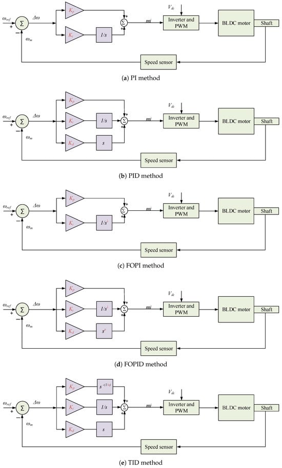
Figure 3.
Speed control of BLDC motor using conventional IO and FO controllers.
Whereas PID has three tunable parameters (derivative gain in addition to and ). Figure 3b shows the PID BLDC speed controller, and it is expressed as:
Some limitations of IO, PI, and PID controllers include reduced design flexibility, limited disturbance rejection capabilities, and deteriorated performance in the presence of uncertainties. However, FO-based control schemes have been proven to perform better compared to their IO PI and PID counterparts. The FOPI has one more tunable parameter (integrator FO operator ) in addition to the two tunable gains ( and ). Figure 3c shows the FOPI BLDC speed controller, and it is expressed as:
The FOPID includes two more FO tunable parameters (the derivative FO operator and ) in addition to the three tunable gains (, , and ). Figure 3d shows the FOPID BLDC speed controller and is expressed as:
Including and in FO-based schemes improves controlled plant performance and enhances the system dynamics and disturbance rejection capability. Another FO scheme based on TID has also been introduced as an intermediate solution between PID and FOPID. The TID scheme includes the tilt gain () and the tilt operator n, which is a real number between 2 and 10. Figure 3e shows the TID BLDC speed controller, and it is expressed as:
Based on the aforementioned mini-review of existing controllers, this paper presents an enhanced, modified hybrid non-integer FO speed controller for BLDC motors. The speed controller is based on a hybrid FO controller, which inherently incorporates the merits of FOPI, TID, and FOPID control structures and branches within a single, hybridized structure by including their respective control terms. The proposed control is constructed using a hybrid proportional-tilt-fractional-order integrator-derivative with filter (PTFOIDN) controller. The proposed PTFOIDN controller features eight tunable parameters, allowing for more flexible design possibilities. It is expressed as
where is the filter coefficient for the derivative term.
The structure of the proposed PTFOIDN speed controller is shown in Figure 4. The proposed PTFOIDN has four different terms in its structure, which makes it inherently have the benefits of the FOPI, TID, and FOPID controllers and their structure control terms. Having the main components and control terms of the FOPI and FOPID enhances the system’s design flexibility, improving the rejection and treatment of disturbances across a wider range of conditions. Furthermore, the inherent inclusion of the FOPID branches is capable of handling multiple control objectives simultaneously over a wider range of the system’s operational dynamics than PI- and PID-based IO systems. However, the inclusion of the tilt term with FOPI and FOPID in the proposed PTFOIDN speed controller presents a better capability to reject disturbances in BLDC speed control systems. In general, the proposed combination of PTFOIDN enhances the robustness of BLDC speed control against various existing uncertainties.
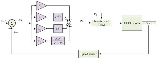
Figure 4.
Proposed PTFOIDN BLDC control structure.
The structure of the proposed PTFOIDN speed controller combines the characteristics of the FOPI and FOPI features with the TID features. The inclusion of FOPI and FOPID enhances the system’s design flexibility and improves the rejection and treatment of disturbances across a wider range of conditions. Furthermore, the FOPID part is capable of handling multiple control objectives simultaneously over a wider range of the system’s operational dynamics than PI- and PID-based IO systems. However, the inclusion of the tilt term with FOPI and FOPID in the proposed PTFOIDN speed controller presents a better capability to reject disturbances in BLDC speed control systems. In general, the proposed combination of PTFOIDN enhances the robustness of BLDC speed control against various existing uncertainties.
The principal features and characteristics of the inclusion of the four terms can be summarized as follows:
- Including the proportional term decreases the system’s rise time, improving its responsiveness to tracking errors. However, higher proportional term values decrease the system’s stability margin and increase the overshoot values. Furthermore, it cannot guarantee zero steady-state error.
- Using the FO integrator improves the system’s steady state and helps minimize steady-state errors. The use of the FO integrator rather than the IO one adds more flexibility to control design procedures.
- Using the FO tilt term adds more flexibility to the controller through one more design parameter. The FO tilt increases the system’s disturbance rejection capabilities and enhances the robustness of the controller to various parametric uncertainties.
- Including the FO derivative term helps in reducing the high overshoot values and hence improving the system’s transient response and balancing the effects of proportional term design. Additionally, being a FO derivative adds one more design parameter to the control system design. Using a filtering term eliminates the expected high-frequency disturbances in the system and addresses the commonly known realizability problems associated with derivative terms.
- The inclusion of FO terms in integration and derivative terms provides better flexibility in designing the controller compared to IO terms in traditional PID controllers. Two more parameters are available for tuning due to the replacement of IO terms with FO ones.
It has become clear that the new proposed PTFOIDN speed controller combines the effectiveness of FOPI and FOPID with TID controllers, leading to improved robustness and stability of the controlled system. Furthermore, an optimized parameter through MPA optimized for the proposed PTFOIDN speed controller presents an additional benefit to the proposed BLDC speed controller. By doing this, lower transient times with reduced overshoot and undershoot responses can be achieved using the new proposed PTFOIDN BLDC speed controller.
It can be seen from (31) that the proposed PTFOIDN speed controller has eight tunable parameters. The conventional mathematical formulation based on control theory faces several complex issues and steps in the design, especially in the case of FO speed controllers. Recent developments in metaheuristic optimizers have proven their suitability and efficacy in designing optimal values for complex control methods in various applications. Furthermore, employing metaheuristic-based control design methods ensures the optimal set of parameters is obtained, rather than optimizing parameters individually. The MPA is selected in this work for designing the proposed FO speed controller.
4. Proposed Control Parameter Design
4.1. Marine Predators Algorithm
The primary impact of MPA is the shared hunting behavior of sea predators. Predators employ two distinct strategies when attacking their prey: Lévy and Brownian motions []. The Lévy strategy searches mostly with short steps, occasionally making long jumps. In contrast, Brownian motion covers the area using more uniform and consistent steps compared to Lévy walks. Therefore, the Lévy strategy is more suitable for exploitation, while Brownian motion is more effective for exploration. To integrate these two strategies, predators adjust their approach according to the velocity ratio of their prey relative to themselves. A flowchart illustrating the MPA is presented in Figure 5 []. The development steps of the MPA will be explained in the subsections below.
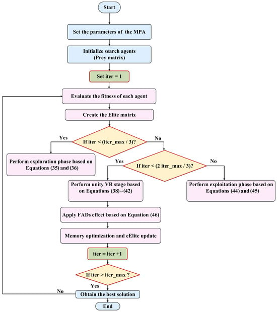
Figure 5.
Flow diagram representing the MPA optimizer process.
4.1.1. Initialization
The initial step of the algorithm involves uniformly allocating solutions throughout the solution space. The initialization step is explained below []:
where and denote the lower and upper bounds of the constrained optimization problem, and r represents a random number in the range [0, 1]. Vector notation is used instead of scalar quantities to represent the multidimensional nature of the optimization problem. Each search agent operates in a multi-dimensional space, where each dimension corresponds to a tunable parameter of the PTFOIDN controller. This vector-based representation enables the simultaneous update of all parameters, thereby enhancing the efficiency of the optimization process.
4.1.2. Elite and Prey Matrix Development
The theory of natural selection suggests that the most efficient predators in nature possess superior hunting skills. Consequently, the top predators are selected to generate an Elite Matrix (B), which includes the best solutions. It is defined as []:
where denotes the position of the elite search agent in the dimension at iteration t.
Furthermore, prey is considered a search agent as it actively seeks food. Accordingly, a new matrix is created, called the Prey matrix (Y). The predators adjust their positions based on this new matrix. It is defined as [,]:
where denotes the position of the search agent in the dimension.
Optimization Strategy: The MPA optimization strategy is divided into three steps according to the velocity ratio () between the prey and the predator. This strategy is explained as follows:
High velocity ratio: A high velocity ratio occurs when the predator is faster than the prey. In this case, the optimal strategy is to remain stationary during the early exploration phase. The mathematical model is []:
where denotes the iteration number and represents the maximum iteration number. denotes the displacement step size of the search agent , represents a set of random numbers following a Brownian motion, derived from the normal distribution. ⊗ represents the symbol of element-wise multiplication. denotes the best solution in the population. P indicates a fixed value, suggested to be 0.5, as in [,]. represents the position vector of the search agent in the search space. represents a sequence of random values sampled from a uniform distribution within the range [0,1]. When the step size or displacement speed is high during the initial third of iterations, it signifies superior exploration ability.
Unit velocity ratio: This step combines the exploration and exploitation processes. At this stage, the search agents are divided into two halves. One half is responsible for exploration, while the other is responsible for exploitation. The predator is on the lookout for food at this time, while the prey is on the lookout for food. Consequently, if the prey follows a Lévy path, the optimal predator strategy is Brownian motion. This stage is described as follows []:
For the first half of the population
For the second half of the population []:
where indicates a vector consisting of random values to represent the Lévy flights and denotes a factor utilized to control the magnitude of the predator’s Brownian motion.
Low velocity ratio: This stage illustrates the exploitation process, where, at a low velocity ratio (v = 0.1), the predator’s speed exceeds the prey’s speed. The predator applies Lévy flights to enhance its exploitation capability. This stage can be described in mathematical form as follows []:
The living environment of the predator plays a crucial role in shaping its foraging behavior. These external environmental influences include eddy formation and fish aggregating devices (). Including this effect allows the MPA to circumvent the local best solution. The effect of is represented as []:
where = 0.2 represents the probability that FADs could influence the optimization process. represents a vector composed of binary values (0 or 1), and the subscripts , represent the indices of the random prey matrix.
A key feature of the MPA algorithm is that it does not include tunable parameters. In the main algorithm of the authors, there are only two constant values in the algorithm. In (37), (42) and (46), the variable P indicates a fixed value, specifically 0.5, as specified by the main authors of the MPA algorithm []. Additionally, the variable represents the probability that could influence the optimization process, which is given equal to 0.2, as specified by the main authors of the MPA algorithm [].
4.2. Overall Optimization Scheme
Figure 6 shows the overall schematic diagram of the proposed MPA-based optimized PTFOIDN BLDC control method. Feedback is employed from the speed control difference ( = − to determine the objective function for the control optimization process. The integral absolute error (IAE) is selected in this paper for determining the desired objective function for the optimization process. The IAE is represented as follows:
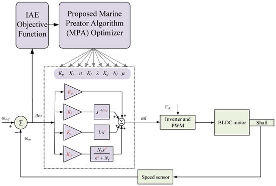
Figure 6.
Proposed MPA-optimized parameter determination method for PTFOIDN BLDC speed control.
The IAE can provide moderate performance in both transient (overshoot values and response time) and steady-state error. It can consider the same weight for the tracking error in the whole drive cycle. Thence, it is selected in the proposed speed controllers optimization process.
A major benefit of employing metaheuristic-based optimizers in control design is their ability to determine and search for an optimal set of parameters, rather than searching for each one individually. This, in turn, guarantees the optimality of the designed controller. In this work, the MPA, a recent method with proven superiority in such problems, is employed for designing the proposed PTFOIDN BLDC control method. As shown in Figure 6, the proposed PTFOIDN BLDC control method has eight tunable controller parameters set. The tunable parameters are (, , , , n, , , and ).
The MPA optimizer searches for the optimum value of each parameter in its predefined search space. At the end of the process, the MPA outputs the optimum set of parameters together. The constraints of the search space for each of the tunable parameters are expressed as:
where and are predefined minimum values and maximum values of limiting boundaries for each parameter. The defined limits in the proposed optimization process are:
The obtained optimum values are: = 0.72787, = 9.8952, n = 2.02, = 10.2415, = 0.9881, = 7.3294, = 0.05, and = 166.6935.
Figure 7 compares the design optimization convergence curves of the MPA algorithm with the slime moulds algorithms (SMA) [], the artificial bee colony (ABC) [], and particle swarm optimization (PSO) [] algorithms. The results show that the MPA algorithm achieves the best convergence performance, followed by ABC, SMA, and PSO. The MPA achieves the fastest and most accurate optimized design. The final objective function of the MPA after 30 iterations is 4.7947, compared with 5.3287 for ABC, 6.8271 for SMA, and 7.73809 for PSO.
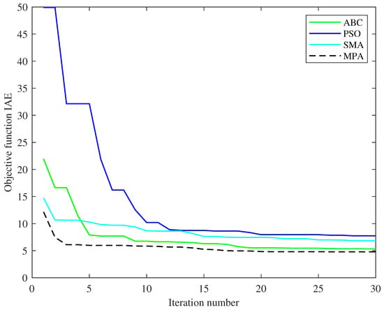
Figure 7.
Comparison of design optimization convergence curves.
5. Results and Comparisons
A simulation case study using the MATLAB/Simulink 2024b environment is implemented to validate the proposed PTFOIDN BLDC control method and MPA-based optimum parameter design. In the previous parts, the system was run offline to determine the best set of tunable speed control parameters. Then, the MPA output of the optimum parameter set is used for online validation and performance comparisons with other speed control schemes. A speed tracking test drive cycle is employed to validate the proposed PTFOIDN BLDC controller. In the results, the PI and FOPI are used in the comparison process of the proposed PTFOIDN BLDC control method. The obtained results are described as follows:
5.1. Speed Tracking Profile
The test speed drive cycle is applied to the BLDC with the optimum parameters of the proposed PTFOIDN controller. Also, the proposed PTFOIDN BLDC control is compared with the optimized PI and FOPI at the same drive cycle. The obtained BLDC speed tracking performance is shown in Figure 8. The speed tracking for the PI speed control is shown in Figure 8a, for the FOPI speed control in Figure 8b, and the proposed PTFOIDN BLDC control in Figure 8c. It can be observed that the PI control exhibits the lowest speed tracking performance, accompanied by the highest speed fluctuations. With the speed step down at time 11 s, the PI-based speed controller drops to 227.943 rpm.
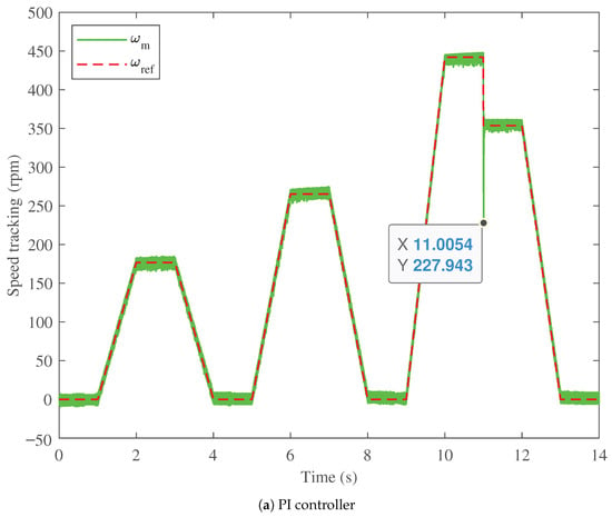
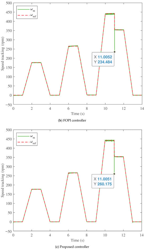
Figure 8.
Speed profile and tracking performance comparison.
For the FOPI, the fluctuations in the speed tracking are lower than those of PI speed control. Additionally, the speed drops to 234.484 rpm at time 11 s, which is better than the PI-based speed control. On the other hand, the proposed PTFOIDN BLDC speed control achieves the best speed tracking performance. The proposed PTFOIDN BLDC speed control has low fluctuations in the speed tracking. Furthermore, the proposed PTFOIDN BLDC speed control drops to only 260.175 rpm at time 11 s. Therefore, the proposed PTFOIDN BLDC speed control achieves the best performance in terms of speed tracking compared to the PI and FOPI control methods.
5.2. Torque Tracking Profile
In this section, the performance and comparison of the torque tracking capabilities are validated for the proposed PTFOIDN BLDC speed control and the conventional PI and FOPI controllers. The results of torque tracking performance are shown in Figure 9. The torque measured for the PI speed control is shown in Figure 9a, and for the FOPI, in Figure 9b. The PI controller exhibits the highest torque ripple in steady state throughout the operating drive cycle. Furthermore, with the speed step change at 11 s, the torque with the PI controller decreases to −23.8638 N.m. At the same time, the FOPI has lower torque ripple in the steady state than the PI control. Furthermore, the torque decreases to −24.0032 N.m. with the speed step change at 11 s, which is the worst case among the compared controllers. The proposed PTFOIDN BLDC speed control provides the lowest torque ripple fluctuation in steady state, as shown in Figure 9c. Additionally, the proposed PTFOIDN BLDC speed control exhibits a torque drop of −21.5783 N.m. at the step change in speed tracking at 11 s. This value is the best among the three evaluated controllers. This, in turn, reflects the reduced torque ripple compared to other traditional controllers.
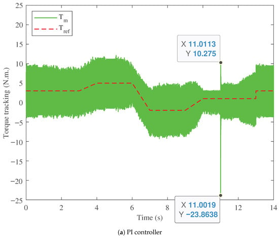
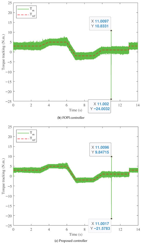
Figure 9.
Torque profile performance comparison.
5.3. Stator Current and Voltage Profiles
Figure 10 shows the stator current comparison of the three BLDC motor speed controllers considered. The stator currents are compared among the three in steady state and during step speed changes. Figure 10a shows the stator current for the PI controller, Figure 10b for the FOPI controller, and Figure 10c for the proposed PTFOIDN BLDC speed control. It can be seen that the PI has high current values, which makes it less efficient and results in higher power losses. Additionally, at the step speed change at 11 s, the current spike is 25.2579 A. For the FOPI, it has lower current values than the PI, making it more efficient. However, it has a stator current spike of 25.3009 at time 11 s. In contrast, the proposed PTFOIDN BLDC speed control achieves the lowest stator current values. In addition, the stator current spike at time 11 s is 22.6228 A, which is the lowest spike among the compared controllers. The performance of the stator voltage for the three controllers is shown in Figure 11. The results show that the three controllers are free from stator voltage spikes for the tested drive cycle.
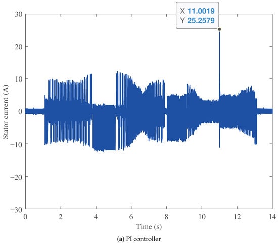
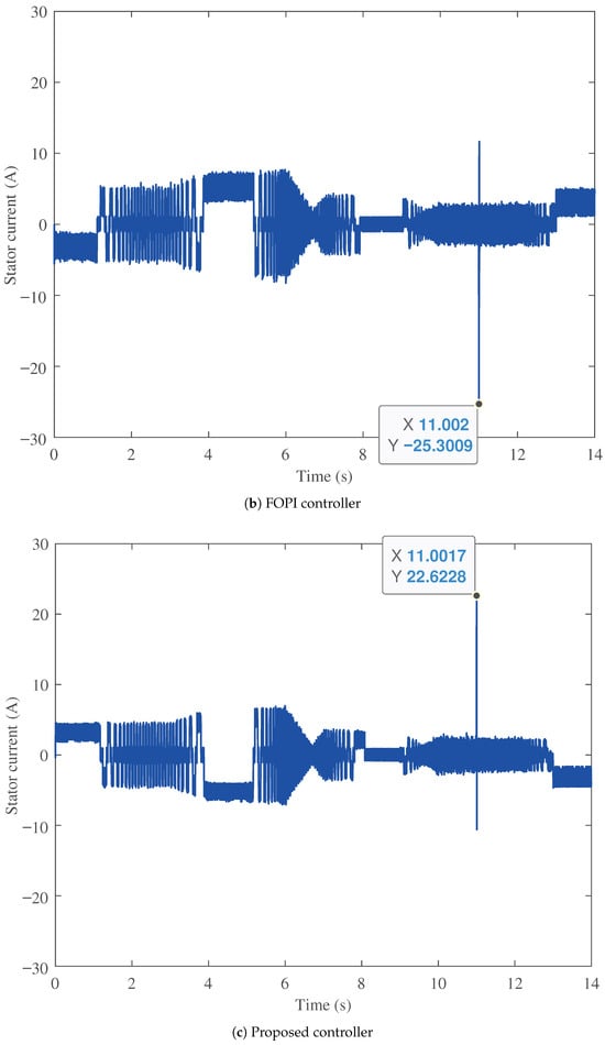
Figure 10.
Stator current profile performance comparison.
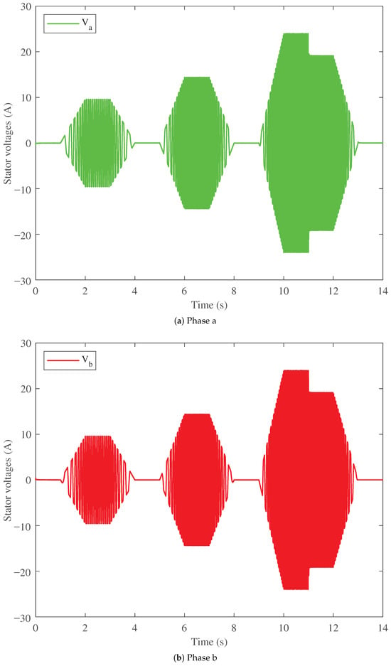
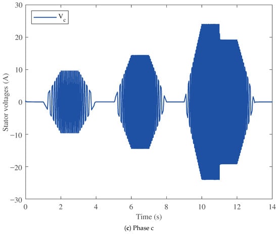
Figure 11.
Stator voltage profile performance of the proposed controller.
5.4. Battery Side Performance
Another comparison is made in terms of the battery side (input DC source) for the electromobility application between the three controllers, as shown in Figure 12 and Figure 13. The performance of the battery voltage of the three controllers is shown in Figure 12a. The PI controller (in green) has the highest battery voltage ripple among the three controllers, followed by the FOPI controller. The proposed PTFOIDN BLDC speed control (in red) has the lowest battery voltage ripple. In addition, it exhibits the lowest battery voltage spike at 11 s, compared to the PI and FOPI controllers.
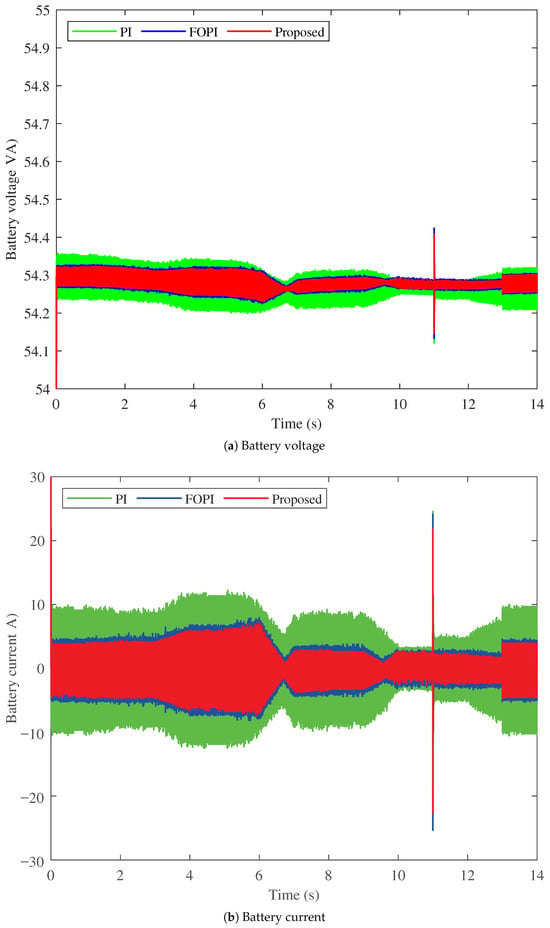
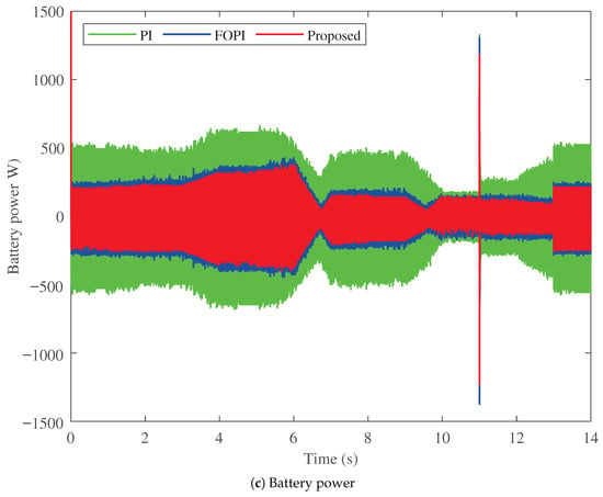
Figure 12.
Battery side performance comparison of studied methods.
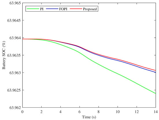
Figure 13.
Battery SoC comparison between the studied methods for one drive cycle.
The performance of the battery currents supplied by the three controllers is shown in Figure 12b. The results show that the proposed PTFOIDN BLDC speed control minimizes the battery current with low current ripples, confirming its most efficient performance among the speed controllers studied. Another study is shown in Figure 12c for the battery power in the three control cases. The improved battery voltage and current performance of the proposed PTFOIDN BLDC speed control, as shown above, is reflected in its lowest power absorption. The FOPI follows it, and then the PI controller, as having the highest power absorption (and hence the least efficient).
The battery SoC for the three controllers for the drive cycle is compared in Figure 13. It can be seen that the high-power absorption of the PI results in a lower SoC at the end of the drive cycle, which means more charging cycles with continuous operation and reduced lifetime accordingly. The FOPI and the proposed PTFOIDN BLDC speed controller have higher SoC at the end of the drive cycle. The proposed PTFOIDN controller has a slightly higher SoC compared to FOPI. However, with continuous operation, this difference becomes higher. Therefore, a longer battery lifetime can be achieved through long-term continuous operation.
5.5. Summarized Comparison and Discussion
A summarized comparison between the three studied controllers is shown in the Table 1.

Table 1.
Summarized performance comparison of the studied speed controllers.
6. Conclusions
In this paper, an innovative hybrid fractional-order speed controller is proposed for BLDC applications fed by Li-ion batteries in electromobility applications. The proposed speed controller, namely the PTFOIDN controller, inherently incorporates several merits from three widely used speed controllers: the FOPI, TID, and FOPID controllers, by including their respective control terms. The proposed PTFOIDN controller has eight tunable control parameters, compared to the three tunable parameters in FOPI, the four in TID, and the five in FOPID. The increased number of tunable parameters significantly improves the design flexibility of the proposed PTFOIDN BLDC speed controller. Furthermore, MPA, a recent powerful metaheuristic optimizer with proven performance in several applications, is proposed to design the proposed BLDC speed controller. The results obtained from the proposed PTFOIDN controller have been compared with those of the PI and FOPI BLDC speed controllers. The results showed that at sharp speed reference commands of the selected drive cycle, the speed drops to 260.175 rpm compared to a drop to 227.943 rpm with the PI control and a drop of 234.484 rpm with the FOPI controller. Additionally, the PTFOIDN BLDC speed controller consumes less power from Li-ion batteries, resulting in lower thermal stresses and a longer lifespan compared to the PI and FOPI controllers. Future research extension may include hardware-in-loop (HiL) testing and experimental testing. Additionally, the implementation with low-cost microcontrollers can be further extended. Future research investigations include the practical implementations based on hardware-in-the-loop (HiL) and experimental setups, with a simplified implementation of FO controllers.
Author Contributions
Conceptualization, M.A., N.A.N., S.M.S. and W.A.H.; methodology, M.A., N.A.N., S.M.S. and W.A.H.; software, M.A., N.A.N., S.M.S. and W.A.H.; validation, M.A., N.A.N., S.M.S. and W.A.H.; formal analysis, M.A., N.A.N., S.M.S. and W.A.H.; investigation, M.A., N.A.N., S.M.S. and W.A.H.; resources, M.A., N.A.N., S.M.S. and W.A.H.; data curation, M.A., N.A.N., S.M.S. and W.A.H.; writing—original draft preparation, M.A., N.A.N., S.M.S. and W.A.H.; writing—review and editing, M.A., N.A.N., S.M.S. and W.A.H.; visualization, M.A., N.A.N., S.M.S. and W.A.H.; supervision, M.A., N.A.N., S.M.S. and W.A.H.; project administration, M.A.; funding acquisition, M.A. All authors have read and agreed to the published version of the manuscript.
Funding
This research was funded by ANID, Chile FONDECYT Iniciacion 11230430.
Data Availability Statement
Data are contained within the article.
Conflicts of Interest
The authors declare no conflicts of interest.
References
- Si, C.; Chau, K.; Liu, W.; Hou, Y. Optimal scheduling for electric vehicle charging: A review of methods, technologies, and uncertainty management. J. Energy Storage 2025, 131, 117500. [Google Scholar] [CrossRef]
- Kumaresan, N.; Rammohan, A. Adaptive neuro fuzzy inference system based optimized energy management strategy for the power integration of battery and supercapacitor in electric vehicle. J. Energy Storage 2025, 126, 117073. [Google Scholar] [CrossRef]
- Tiwari, H.; Ghosh, A.; Sain, C.; Ahmad, F.; Al-Fagih, L. Modified direct torque control algorithm for regeneration capability of IM driven electric vehicle by using hybrid energy storage system. Renew. Energy Focus 2024, 48, 100534. [Google Scholar] [CrossRef]
- Abhin, A.; Chandrakala, K.V. Hybrid Energy Storage System For an Electric Vehicle Powered by Brushless DC Motor. In Proceedings of the 2018 International Conference on Control, Power, Communication and Computing Technologies (ICCPCCT), Kannur, India, 23–24 March 2018; pp. 497–501. [Google Scholar] [CrossRef]
- Gull, M.S.; Ahmed, I.; Khalid, M.; Arshad, N. Design and optimization of electric vehicle battery swapping stations with integrated storage for enhanced efficiency. J. Energy Storage 2025, 129, 117211. [Google Scholar] [CrossRef]
- Chen, Z.; Chen, J.; Zhu, Z.; Chen, J.; Lv, T.; Qiao, D.; Zheng, Y. Cloud-based estimation of lithium-ion battery life for electric vehicles using equivalent circuit model and recurrent neural network. J. Energy Storage 2025, 114, 115718. [Google Scholar] [CrossRef]
- Ammari, O.; Majdoub, K.E.; Giri, F. Modeling and control of a half electric vehicle including an inverter, an in-wheel BLDC motor and Pacejka’s tire model. IFAC-PapersOnLine 2022, 55, 604–609. [Google Scholar] [CrossRef]
- Lu, L.; Han, X.; Li, J.; Hua, J.; Ouyang, M. A review on the key issues for lithium-ion battery management in electric vehicles. J. Power Sources 2013, 226, 272–288. [Google Scholar] [CrossRef]
- Subbarao, M.; Dasari, K.; Duvvuri, S.S.; Prasad, K.; Narendra, B.; Murali Krishna, V. Design, control and performance comparison of PI and ANFIS controllers for BLDC motor driven electric vehicles. Meas. Sens. 2024, 31, 101001. [Google Scholar] [CrossRef]
- Anshory, I.; Jamaaluddin, J.; Wisaksono, A.; Sulistiyowati, I.; Hindarto; Rintyarna, B.S.; Fudholi, A.; Rahman, Y.A.; Sopian, K. Optimization DC-DC boost converter of BLDC motor drive by solar panel using PID and firefly algorithm. Results Eng. 2024, 21, 101727. [Google Scholar] [CrossRef]
- Zhang, R.; Gao, L. The Brushless DC motor control system Based on neural network fuzzy PID control of power electronics technology. Optik 2022, 271, 169879. [Google Scholar] [CrossRef]
- Sayed, K.; El-Zohri, H.H.; Ahmed, A.; Khamies, M. Application of Tilt Integral Derivative for Efficient Speed Control and Operation of BLDC Motor Drive for Electric Vehicles. Fractal Fract. 2024, 8, 61. [Google Scholar] [CrossRef]
- Kommula, B.N.; Kota, V.R. Direct instantaneous torque control of Brushless DC motor using firefly Algorithm based fractional order PID controller. J. King Saud Univ.-Eng. Sci. 2020, 32, 133–140. [Google Scholar] [CrossRef]
- Vanchinathan, K.; Selvaganesan, N. Adaptive fractional order PID controller tuning for brushless DC motor using Artificial Bee Colony algorithm. Results Control Optim. 2021, 4, 100032. [Google Scholar] [CrossRef]
- Vanchinathan, K.; Valluvan, K.R.; Gnanavel, C.; Gokul, C. Design methodology and experimental verification of intelligent speed controllers for sensorless permanent magnet Brushless DC motor: Intelligent speed controllers for electric motor. Int. Trans. Electr. Energy Syst. 2021, 31, e12991. [Google Scholar] [CrossRef]
- Karaboga, D.; Gorkemli, B.; Ozturk, C.; Karaboga, N. A comprehensive survey: Artificial bee colony (ABC) algorithm and applications. Artif. Intell. Rev. 2012, 42, 21–57. [Google Scholar] [CrossRef]
- Rajasekhar, A.; Kumar Jatoth, R.; Abraham, A. Design of intelligent PID/PIλDμ speed controller for chopper fed DC motor drive using opposition based artificial bee colony algorithm. Eng. Appl. Artif. Intell. 2014, 29, 13–32. [Google Scholar] [CrossRef]
- Ibrahim, H.; Hassan, F.; Shomer, A.O. Optimal PID control of a brushless DC motor using PSO and BF techniques. Ain Shams Eng. J. 2014, 5, 391–398. [Google Scholar] [CrossRef]
- Premkumar, K.; Manikandan, B. Speed control of Brushless DC motor using bat algorithm optimized Adaptive Neuro-Fuzzy Inference System. Appl. Soft Comput. 2015, 32, 403–419. [Google Scholar] [CrossRef]
- Mohamed, A.A.A.; Mohamed, Y.S.; El-Gaafary, A.A.; Hemeida, A.M. Optimal power flow using moth swarm algorithm. Electr. Power Syst. Res. 2017, 142, 190–206. [Google Scholar] [CrossRef]
- Issa, M. Enhanced Arithmetic Optimization Algorithm for Parameter Estimation of PID Controller. Arab. J. Sci. Eng. 2022, 48, 2191–2205. [Google Scholar] [CrossRef]
- Hemeida, M.; Osheba, D.; Alkhalaf, S.; Fawzy, A.; Ahmed, M.; Roshdy, M. Optimized PID controller using Archimedes optimization algorithm for transient stability enhancement. Ain Shams Eng. J. 2023, 14, 102174. [Google Scholar] [CrossRef]
- Potnuru, D.; Alice Mary, K.; Sai Babu, C. Experimental implementation of Flower Pollination Algorithm for speed controller of a BLDC motor. Ain Shams Eng. J. 2019, 10, 287–295. [Google Scholar] [CrossRef]
- Angel, L.; Viola, J. Design and statistical robustness analysis of FOPID, IOPID and SIMC PID controllers applied to a motor-generator system. IEEE Lat. Am. Trans. 2015, 13, 3724–3734. [Google Scholar] [CrossRef]
- Viola, J.; Angel, L.; Sebastian, J.M. Design and robust performance evaluation of a fractional order PID controller applied to a DC motor. IEEE/CAA J. Autom. Sin. 2017, 4, 304–314. [Google Scholar] [CrossRef]
- De Keyser, R.; Muresan, C.I.; Ionescu, C.M. A novel auto-tuning method for fractional order PI/PD controllers. ISA Trans. 2016, 62, 268–275. [Google Scholar] [CrossRef]
- Fergani, N.; Charef, A. Process step response based fractional PImuDλ controller parameters tuning for desired closed loop response. Int. J. Syst. Sci. 2014, 47, 521–532. [Google Scholar] [CrossRef]
- Kesarkar, A.A.; Selvaganesan, N. Tuning of optimal fractional-orderPIDcontroller using an artificial bee colony algorithm. Syst. Sci. Control Eng. 2014, 3, 99–105. [Google Scholar] [CrossRef]
- Yang, J.; Huang, W.; Xia, B.; Mi, C. The improved open-circuit voltage characterization test using active polarization voltage reduction method. Appl. Energy 2019, 237, 682–694. [Google Scholar] [CrossRef]
- Yang, J.; Cai, Y.; Pan, C.; Mi, C. A novel resistor-inductor network-based equivalent circuit model of lithium-ion batteries under constant-voltage charging condition. Appl. Energy 2019, 254, 113726. [Google Scholar] [CrossRef]
- Zhang, S.; Guo, X.; Dou, X.; Zhang, X. A data-driven coulomb counting method for state of charge calibration and estimation of lithium-ion battery. Sustain. Energy Technol. Assess. 2020, 40, 100752. [Google Scholar] [CrossRef]
- Arun Kumar, B.; Marutheswar, G.V. Multi Quadrant Operation of Brushless Direct Current Motor Drive with PI and Fuzzy Logic Controllers. Int. J. Inf. Eng. Electron. Bus. 2019, 11, 25–32. [Google Scholar] [CrossRef]
- Al-Fiky, H.T.; Asfoor, M.S.; Yacoub, M.I.; Sharaf, A.H. Speed Control Modeling for In-Wheel Permanent Magnet Brushless DC Motors for Electric Vehicles. In Proceedings of the 2019 24th International Conference on Methods and Models in Automation and Robotics (MMAR), Miedzyzdroje, Poland, 26–29 August 2019; pp. 438–443. [Google Scholar] [CrossRef]
- Faramarzi, A.; Heidarinejad, M.; Mirjalili, S.; Gandomi, A.H. Marine Predators Algorithm: A nature-inspired metaheuristic. Expert Syst. Appl. 2020, 152, 113377. [Google Scholar] [CrossRef]
- Aly, M.; Ahmed, E.M.; Rezk, H.; Mohamed, E.A. Marine Predators Algorithm Optimized Reduced Sensor Fuzzy-Logic Based Maximum Power Point Tracking of Fuel Cell-Battery Standalone Applications. IEEE Access 2021, 9, 27987–28000. [Google Scholar] [CrossRef]
- Mugemanyi, S.; Qu, Z.; Rugema, F.X.; Dong, Y.; Wang, L.; Bananeza, C.; Nshimiyimana, A.; Mutabazi, E. Marine predators algorithm: A comprehensive review. Mach. Learn. Appl. 2023, 12, 100471. [Google Scholar] [CrossRef]
- Abdel-Basset, M.; Mohamed, R.; Elhoseny, M.; Bashir, A.K.; Jolfaei, A.; Kumar, N. Energy-Aware Marine Predators Algorithm for Task Scheduling in IoT-Based Fog Computing Applications. IEEE Trans. Ind. Inform. 2021, 17, 5068–5076. [Google Scholar] [CrossRef]
- Li, S.; Chen, H.; Wang, M.; Heidari, A.A.; Mirjalili, S. Slime mould algorithm: A new method for stochastic optimization. Future Gener. Comput. Syst. 2020, 111, 300–323. [Google Scholar] [CrossRef]
- Karaboga, D.; Basturk, B. A powerful and efficient algorithm for numerical function optimization: Artificial bee colony (ABC) algorithm. J. Glob. Optim. 2007, 39, 459–471. [Google Scholar] [CrossRef]
- Kennedy, J.; Eberhart, R. Particle swarm optimization. In Proceedings of the ICNN’95—International Conference on Neural Networks, Perth, Australia, 27 November–1 December 1995; Volume 4, pp. 1942–1948. [Google Scholar] [CrossRef]
Disclaimer/Publisher’s Note: The statements, opinions and data contained in all publications are solely those of the individual author(s) and contributor(s) and not of MDPI and/or the editor(s). MDPI and/or the editor(s) disclaim responsibility for any injury to people or property resulting from any ideas, methods, instructions or products referred to in the content. |
© 2025 by the authors. Licensee MDPI, Basel, Switzerland. This article is an open access article distributed under the terms and conditions of the Creative Commons Attribution (CC BY) license (https://creativecommons.org/licenses/by/4.0/).