Abstract
A new proposed method is presented, where multiple antennas have been applied into HIPERLAN/2 system in addition to employing space-time diversity technique, especially the Alamouti technique. The suggested approach is used to cancel or reduce the effect of the transmitted power using a feedback signal process within the transceiver unit, especially when the antennas are closely located and working in full-mode duplexing. Several parameters including the transmitted power, the received power, and the feedback accuracy have been considered for testing the performance of the system in term of the signal to noise ratio (SNR) versus bit error rate (BER). A software programme using MATLAB and Simulink is implemented to evaluate the proposed method. The results showed that the system performance is heavily dependent on the amount of the mismatch in the feedback, the received power, and the transmitted power. The performance of the system decreases as the feedback accuracy increases when the transmitted power and the received power are constant. At the same time, the performance of the system decreases as the transmitted power increases when the received power and the mismatch are constant. Finally, the increase in the received power enhances the system performance when the other parameters are constant.
1. Introduction
The demand for employing multiple input multiple output (MIMO) system has been increased to increase the data rate and to utilize the available bandwidth effectively [1,2,3,4]. Wireless communications systems have four types of systems in terms of the number of transmitting and receiving antennas. The first traditional system is Single Input Single Output (SISO), which uses one transmitting antenna and one receiving antenna. Whereas the second type is called, Single Input Multiple Output (SIMO), which has one transmitting antenna with multiple receiving antennas. The third type is opposite to the second type, where there are multiple antennas at the transmitter and one antenna at the receiver. This type of system called Multiple Input Single Output (MISO). The last type is the MIMO, where there are multiple antennas on both sides. Figure 1 shows the different types of wireless communications.
Figure 1.
The link structures for different wireless communication systems.
In 1896, Guglielmo Marconi changed the world’s perception of wireless communications technologies by transmitting a radio signal from the back of the hill. Since that time, scientists have been working on how to reduce the effect of the impairments that are caused by the environment [5]. At the same time, researchers have been working on how to mitigate the multipath effect in wireless and mobile communication systems caused by the obstacles in the propagation environment in order to increase the spectral efficiency of wireless systems. At Bell laboratories, in 1984, Jack Winter developed one of the earliest MIMO systems; his work was a starting point for researchers to depend on using more than one antenna at the transmit and receive sides [6,7,8,9,10]. Later, the principle of spatial diversity using MIMO was proposed by T. Kailath and A. Paulraj in 1993 [11]. Subsequently, a significant contribution to MIMO subject has been carried out by engineers and academic researchers.
Diversity gain, interference reduction, array gain, and spatial multiplexing are the most important advantages of MIMO systems. However, both maximum multiplexing and maximum diversity cannot be achieved at the same time, so that a kind of trade-off should be taken between them [6,12].
In the early of the 21st century, transmit diversity has become widely implemented because the interference occurs when the signals sent by different transmitting antennas, both the transmitter and receiver need some processes in order to achieve the diversity by cancelling or at least attenuating the spatial diversity. Transmit diversity is preferable, especially in the downlink such as from the base station to the mobile station. There are two types of transmit diversity, which are: open-loop and close-loop. In open-loop transmit diversity; there is no need to know the channel at the transmitter. However, closed-loop systems imply that the transmitter knows the channel.
Space-time coding is the most popular transmit diversity scheme, where the code that applied at the transmitter is known by the receiver. In the early nineties of the last century, space-time coding was suggested. Nevertheless, a great interest in this subject started after the late 1990s. One of the most important schemes in the open-loop diversity is the Alamouti code, where the system performances at the receiver side will be improved without any feedback from the receiver.
In addition, HIgh PERformance wireless Local Area Network (HIPERLAN) system is used as an alternative for the IEEE 802.11 standards. HIPERLAN has four subcategories which are HIPERLAN/1, HIPERLAN/2, HIPERLINK, and HIPERACCESS, where more bandwidth can be obtained compared to other types of LANs. Moreover, the frequency band in this standard is 5 GHz and can support up to 54 Mbit/s [13]. This paper gives a brief introduction about the Alamouti technique, followed by an overview of HIPERLAN/2 system, then a combination of the Alamouti technique with HIPERLAN/2 will be discussed in the third part. Finally, the simulation results and the conclusions will be given.
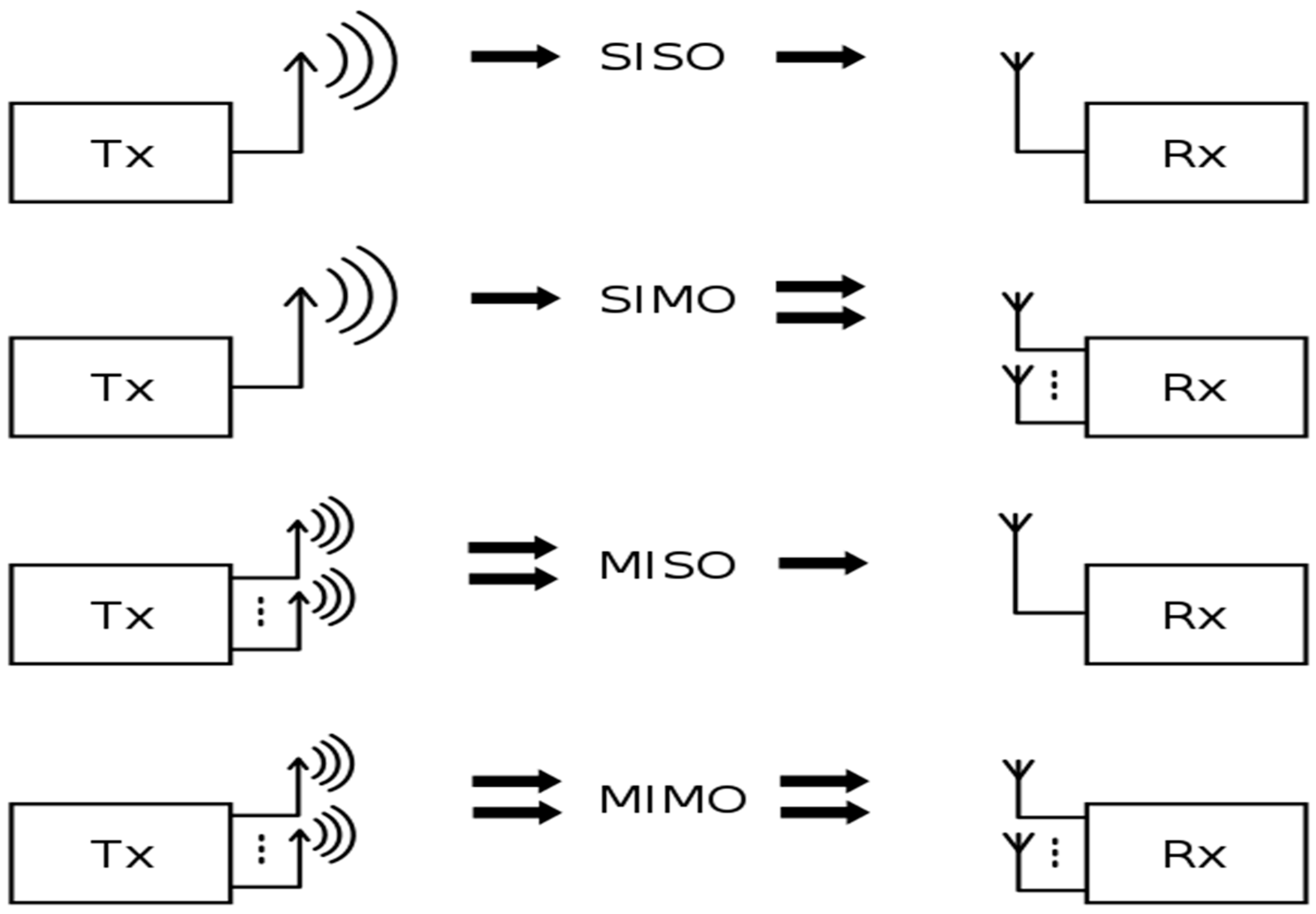
2. Alamouti Technique
The Alamouti technique is one of the simplest techniques which is used for the transmit diversity, which does not need any feedback from the receiver; however, it needs a small computation complexity at the transmitter side. This technique improves the signal quality, capacity, data rate, and error performance at the receiver and requires no bandwidth expansion. The Alamouti scheme can be used to increase the coverage area in wireless systems. Besides, this scheme is effective in the systems in which its capacity is limited by the multipath phenomenon. Alamouti studied two cases; in the first case, Alamouti assumed a system with two transmitting antennas and one receive antenna, while the second case assumed there are two antennas in both transmitted and received sides. This system modulates m-data bits using M-ary modulation to generate the symbols, where , each symbol has a complex value. Alamouti suggests a strategy in sending these symbols during two-time slots. At the first time slot, the first transmitter sends the first symbol , while the second transmitter sends the second symbol . After that, at the second time slot the first transmitter sends the minus complex conjugate of the second symbol , while the second transmitter sends the complex conjugate of the first symbol as shown in the following equation [1,2,4]:
where the first and second rows represent the symbols that will be transmitted by the first and second transmitter, respectively. At the same time, the first column represents the first time slot, while the second row represents the second time slot. The key feature is that the transmitted symbols at first time slot are orthogonal to the second time slot (i.e., ), Alamouti assumed that the channel between the transmitter and the receiver remains constant during the two periods. Concurrently, the channel is known by the receiver. The number of channels is equal to the number of the transmit antennas multiplied by the number of receiver antennas. Therefore, there will be two channels between two transmit antennas and one receiver antenna:
where: h1 and h2 are the channels characteristics between the transmitted antennas of the first user and the receiver antenna of the second user and can be represented as a complex value:
By transmitting the symbols using Equation (1), the received signal for two time slots will be:
where and represent received signal for the first and second time slots respectively. After that, the receiver will combine the two-time slots and send the combined signal to the maximum likelihood detector. The combined signals are:
The combined signals that are shown in Equations (7) and (8) are different from the equations of Maximal Ratio Combining (MRC):
Alamouti noticed that the equations above are equivalent to that obtained from MRC in equations. However, the only difference is the phase of the noise components that do not affect the SNR.
Moreover, higher diversity is needed in many applications where more antennas are used to increase the diversity for both transmitting and receiving sides. In the case of having two transmitting and M receiving antenna, the diversity will be 2M. By using the same way of sending the symbols, the received signal for both antennas during two-time slots are:
where: , , and are representing the interference and the noise at the receiver. are the characteristics of channels between the two transmit antennas and the two receiver antennas. After that, the two time slots of each antenna will be combined and sent to the maximum likelihood detector:
It can be seen clearly that the combined signals of M receiver antennas is the sum of the combined signals of each antenna. At the same time, the diversity that can be getting from one transmit antenna with multiple receiver antennas can be doubled by using two transmit antennas with the same number of receiver antennas.
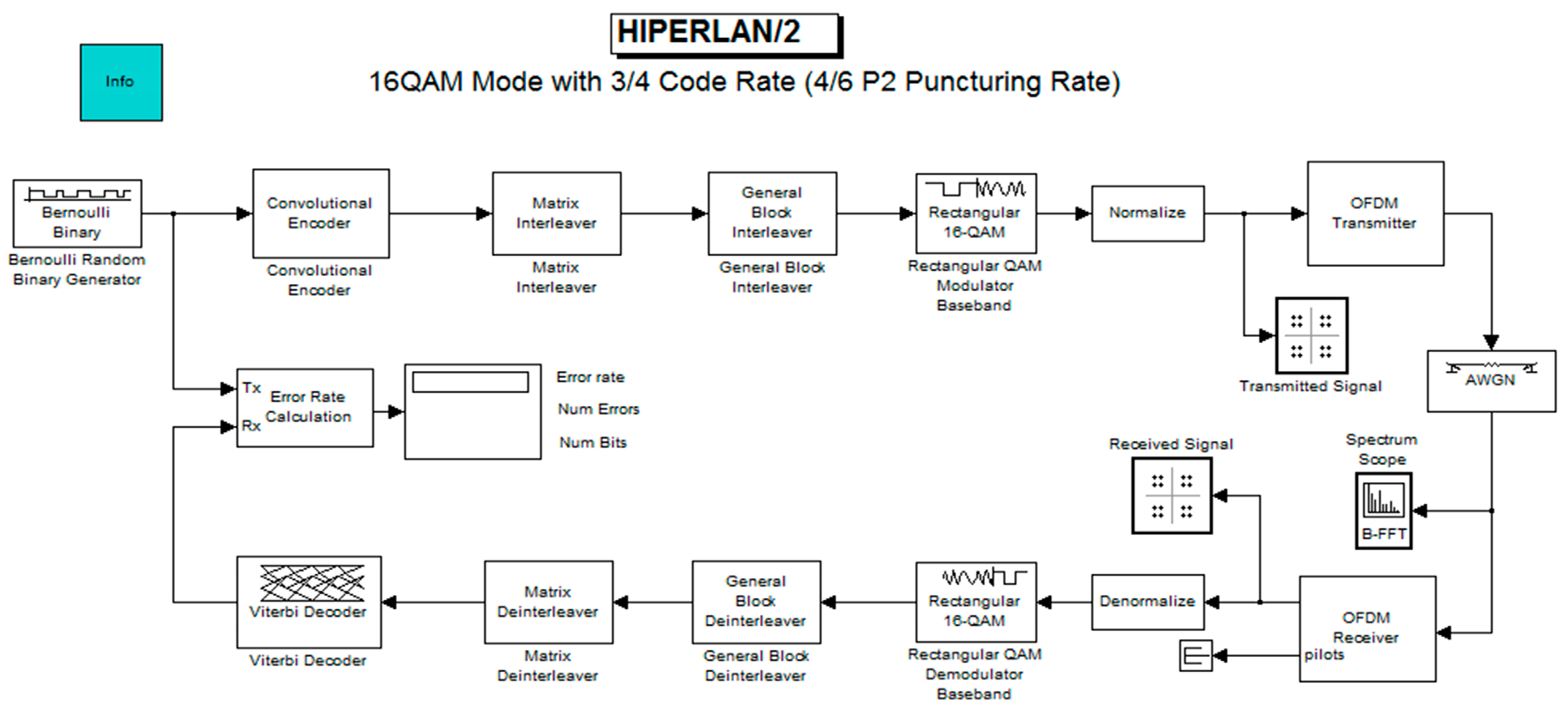
3. HIPERLAN/2 System
HIPERLAN is a standard on digital high-speed wireless communication, developed by ETSI [10,14,15,16]. Orthogonal frequency-division multiplexing (OFDM) is employed to operate in the 5 GHz band [17]. Figure 2 shows the HIPERLAN/2 system.
Figure 2.
Classical HIPERLAN system.
The model of HIPERLAN/2 that exists in the MATLAB consists of several stages; the first stage is the Bernoulli random generator that generates the binary data depending on the probability of zero, followed by the convolutional coder, which codes the data by using one of the polynomials that can be written by using the command (poly2trellis(3, [7 5])). At the same time, the encoder can do the puncturing of encoded data. The third part is the interleaver, which interleaves the data using two types of interleavers (matrix interleaver and equation interleaver). The interleaving perform of the matrix interleaver is done by filling a matrix with symbols row by row, then sending the filled data column by column, whereas equation interleaver rearranges the data depends on specific equation that determine the symbol position without omitting any symbols. The fourth stage is the modulator, which modulates the data using m-modulation scheme, then the output symbols from the modulator will be normalized before sending it by using OFDM transmitter [14,15]. These stages represent the transmitting part. There is a channel of Additive white Gaussian noise (AWGN) type between the transmitter and the receiver. The receiver consists of the OFDM receiver, demodulator, two stages of deinterleavers, and Viterbi decoder. The receiver components work opposite to those components in the transmitter side.
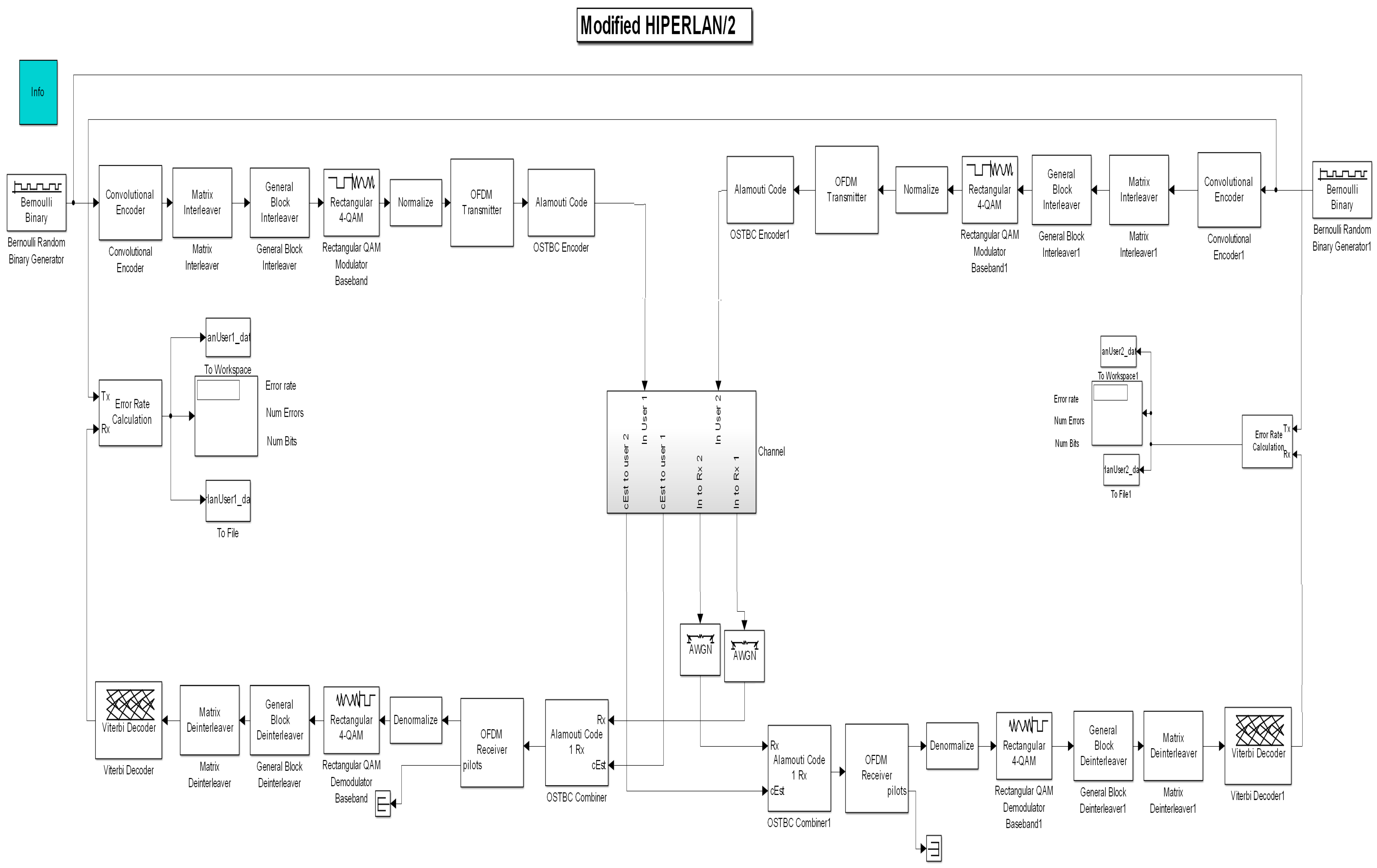
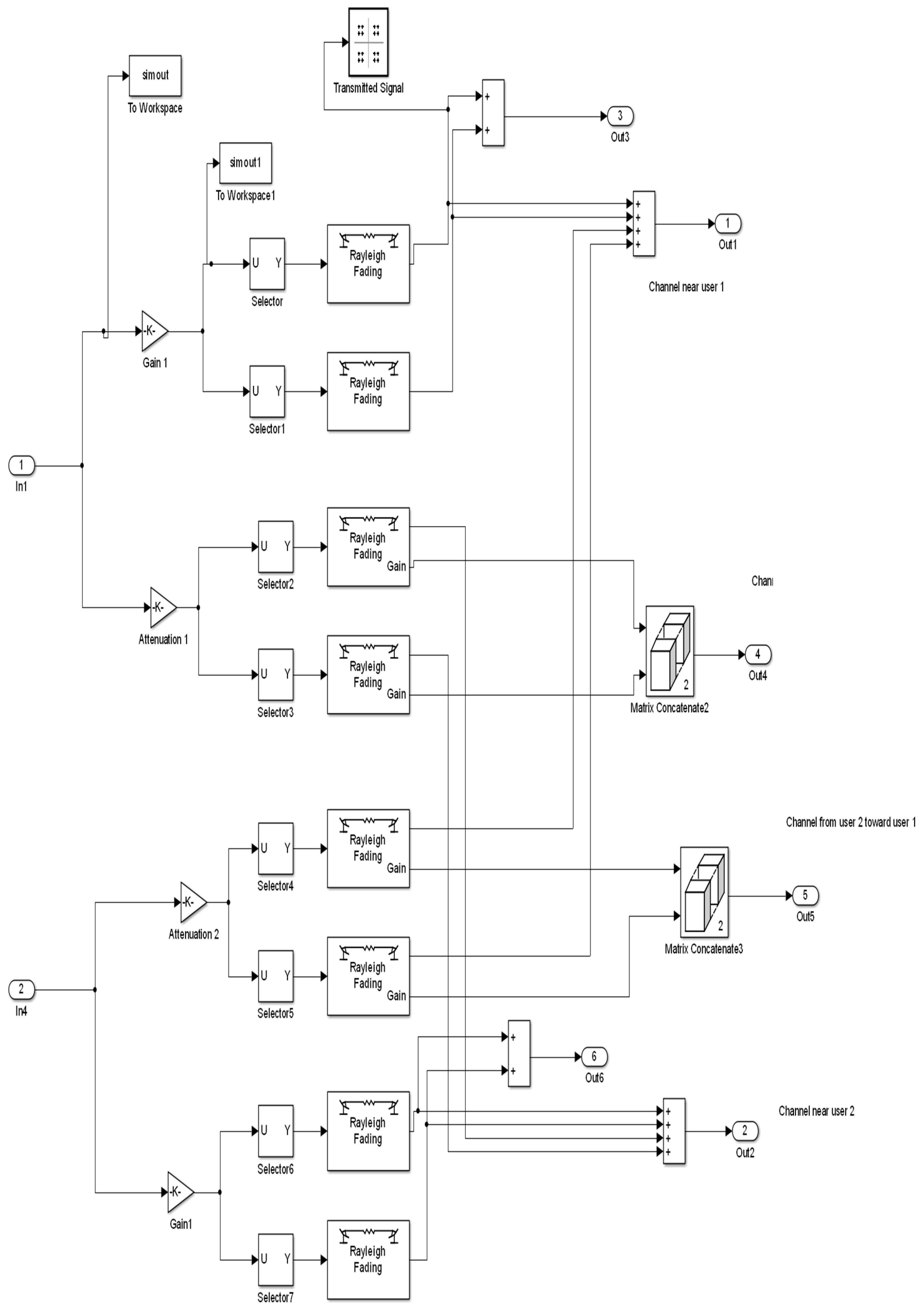
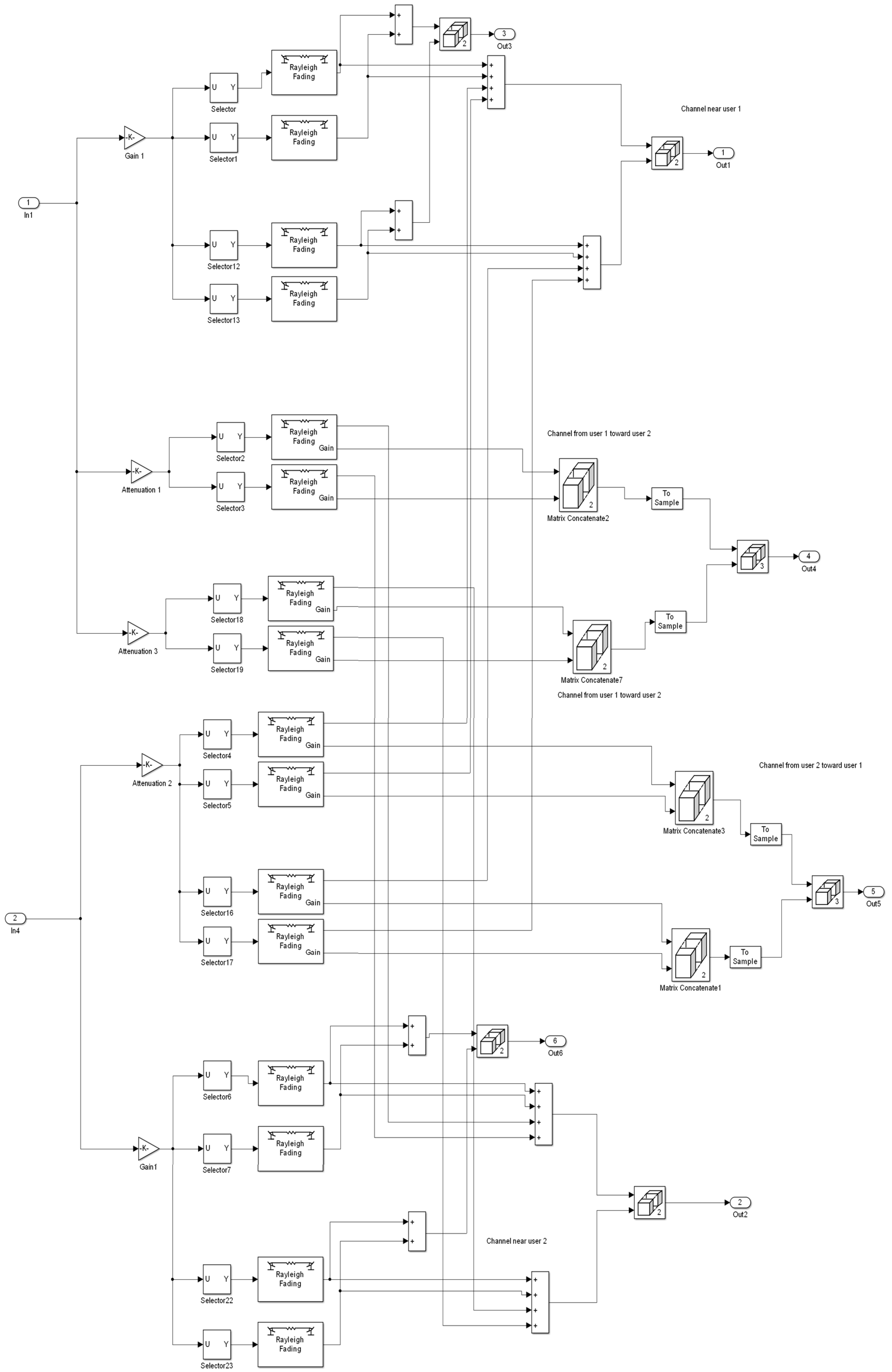
4. HIPERLAN/2 with Open Loop Transmit Diversity Technique
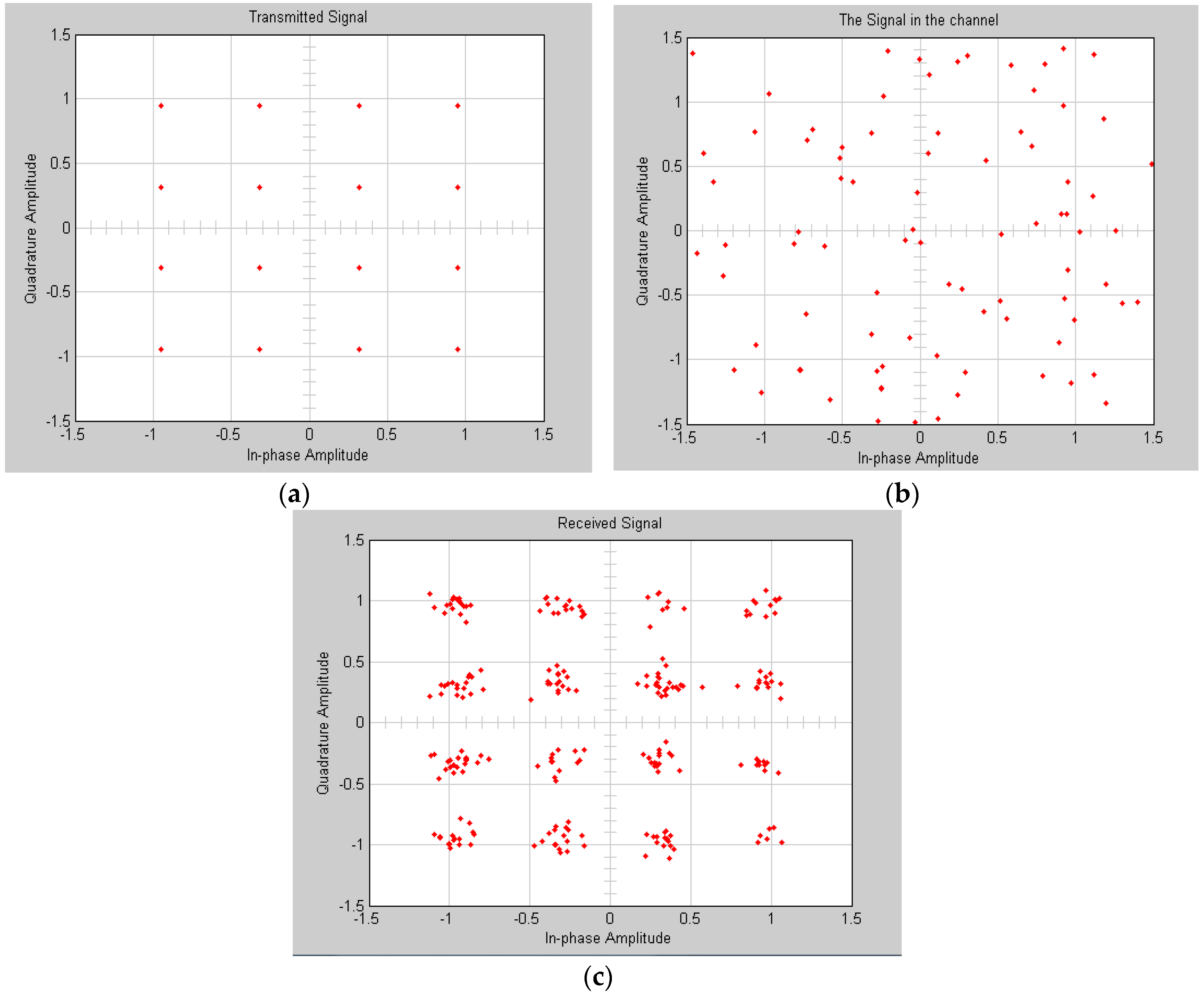
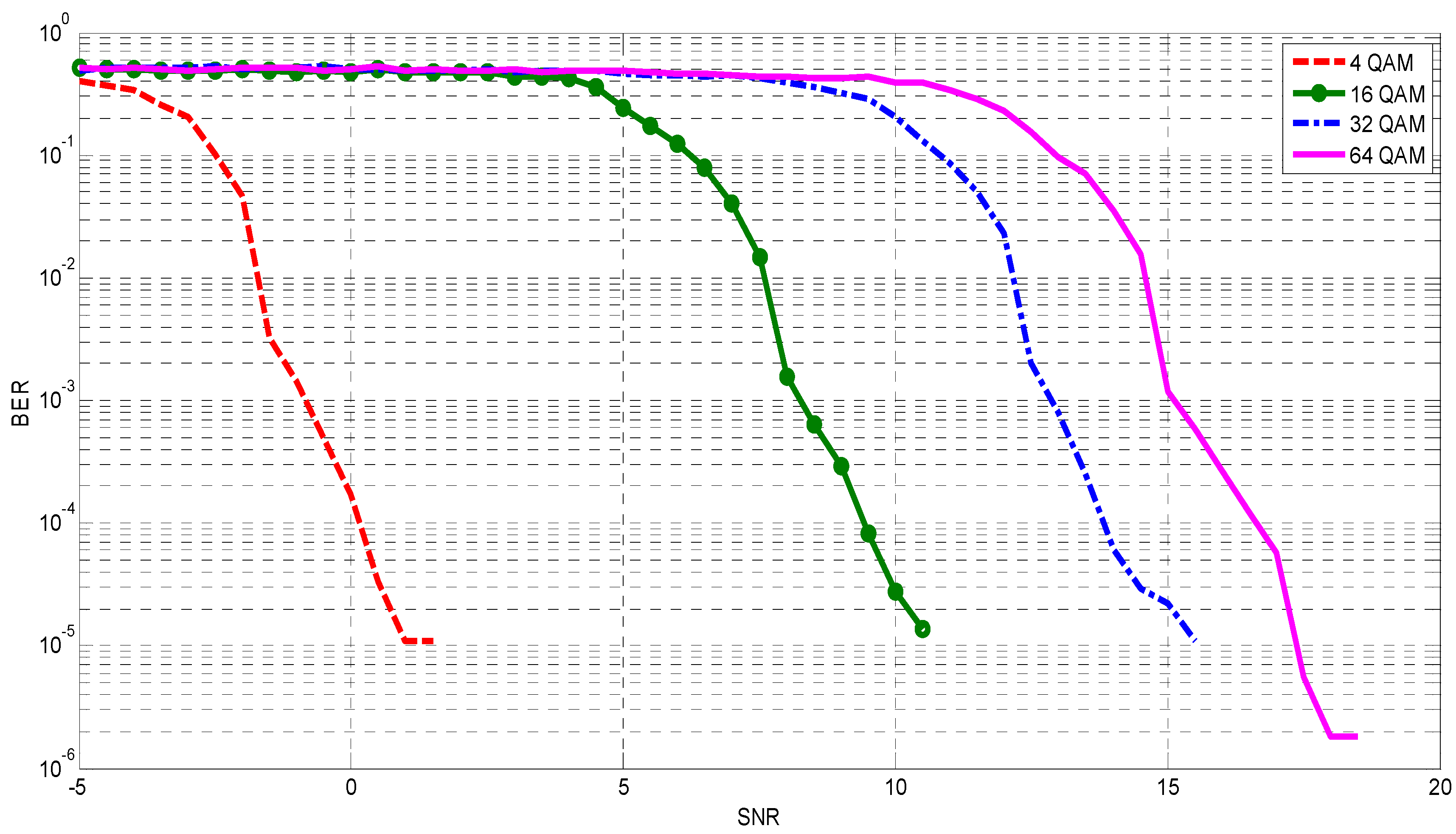
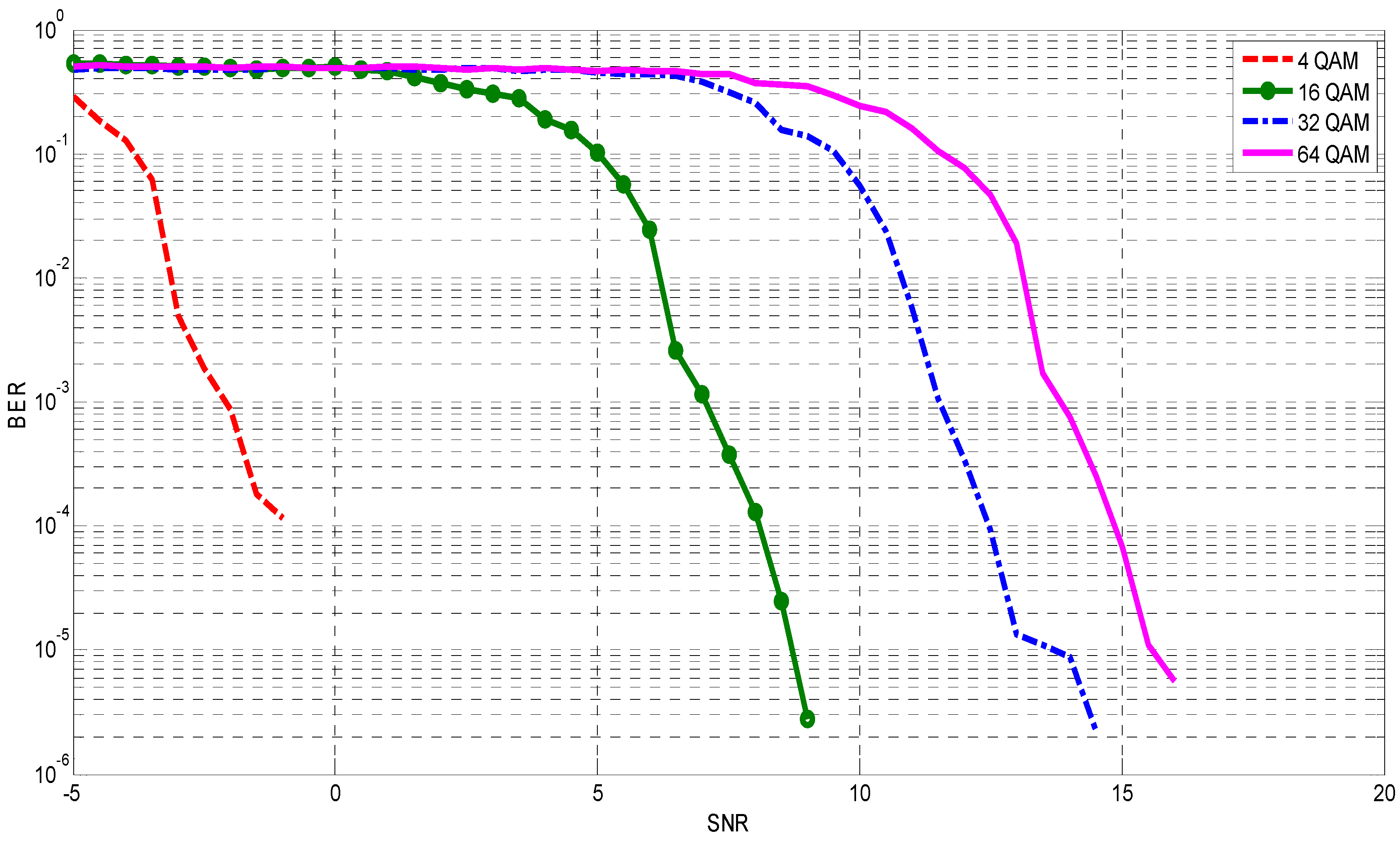
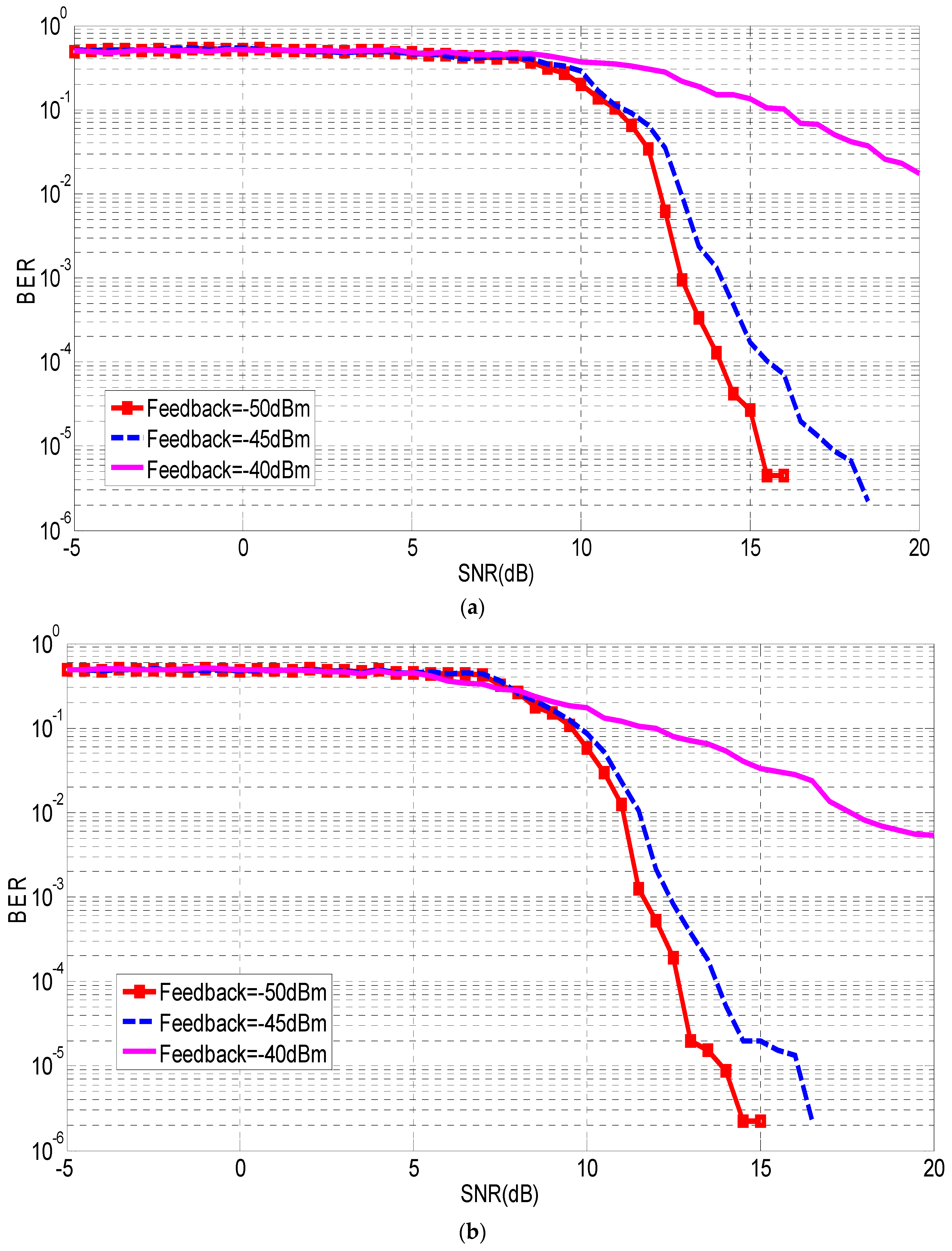
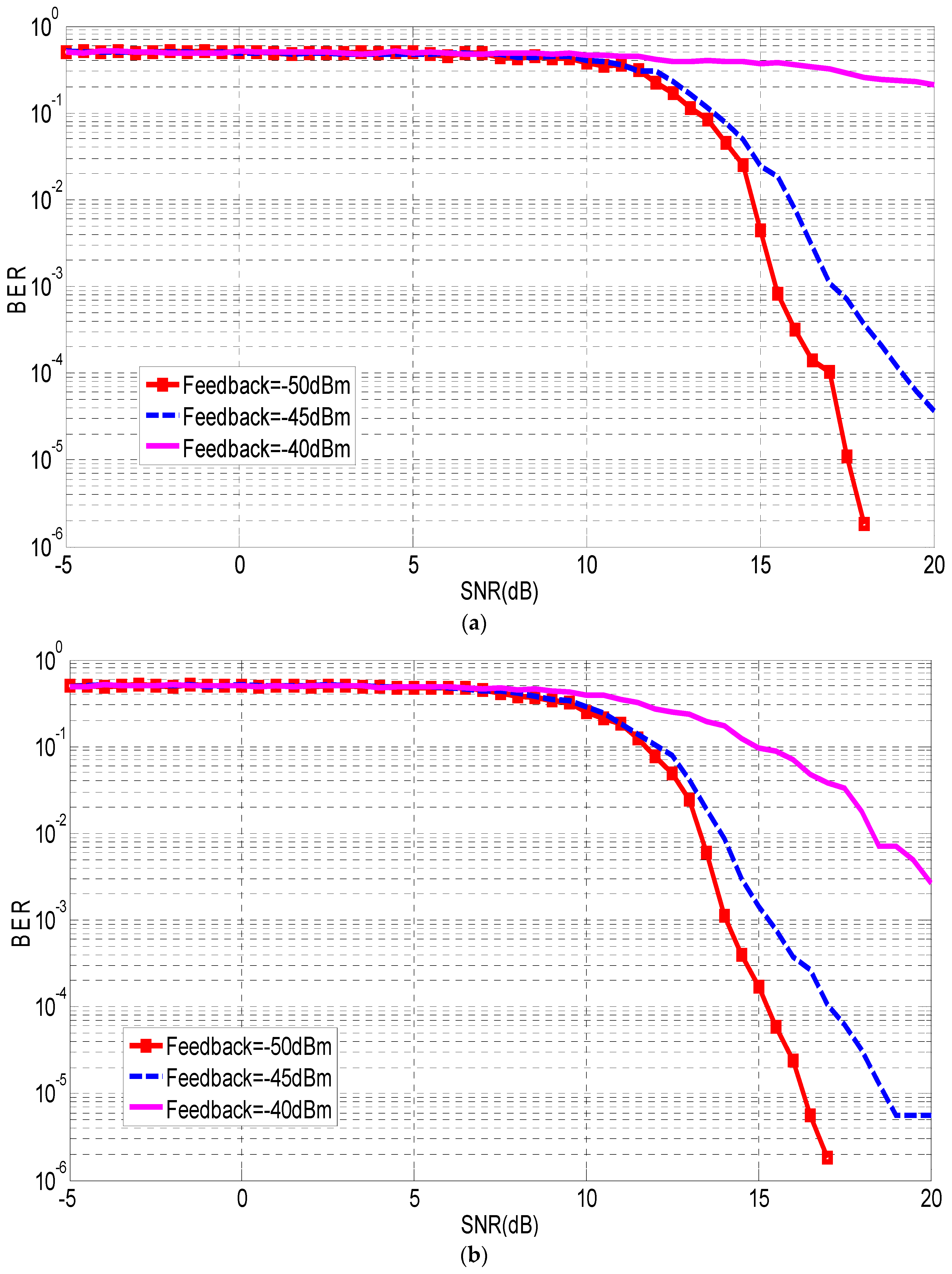
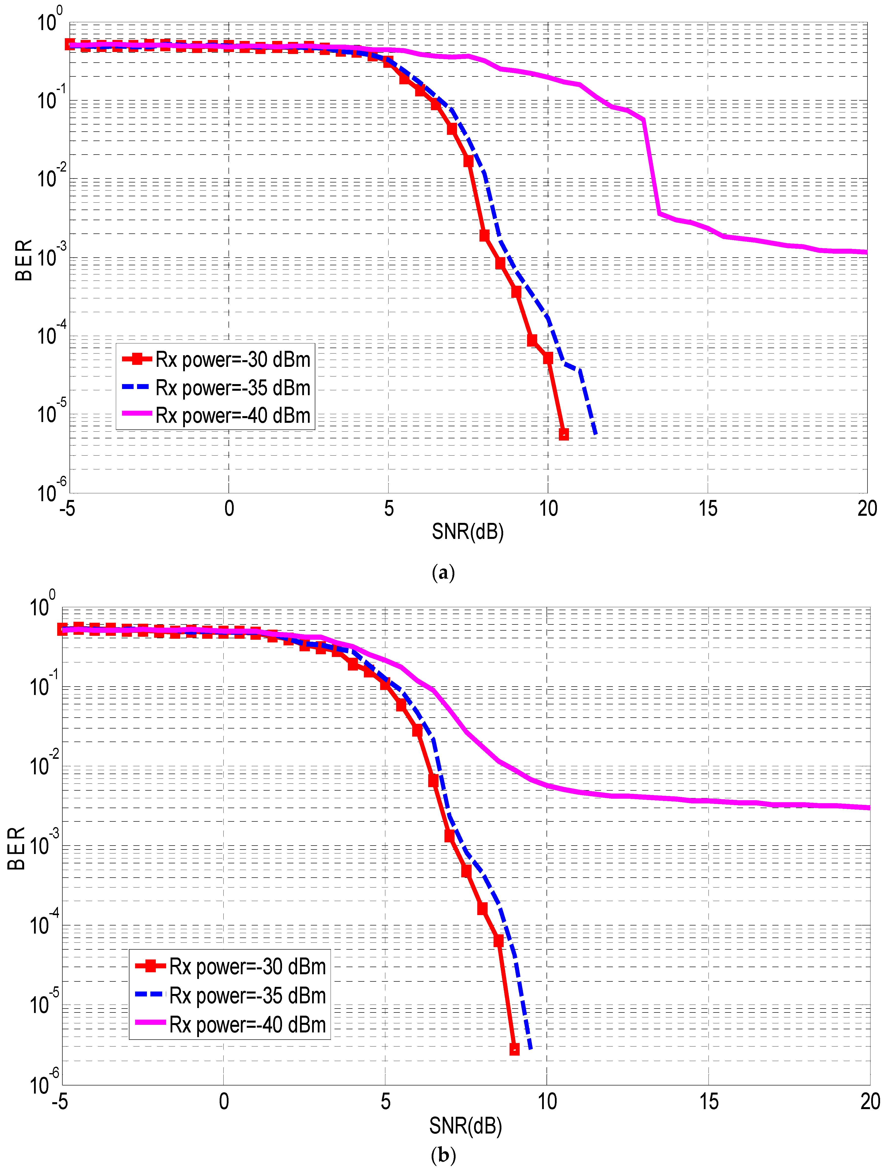
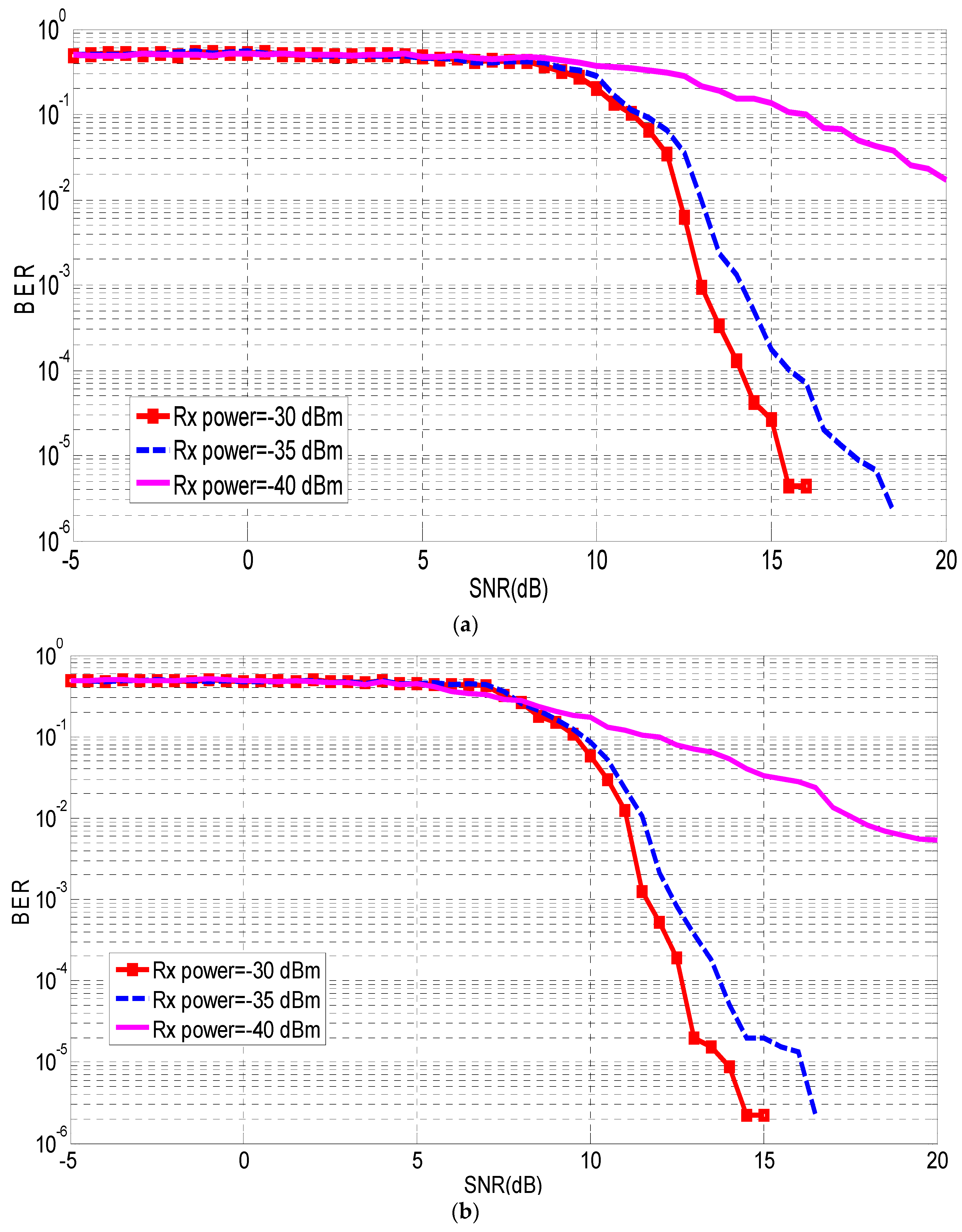
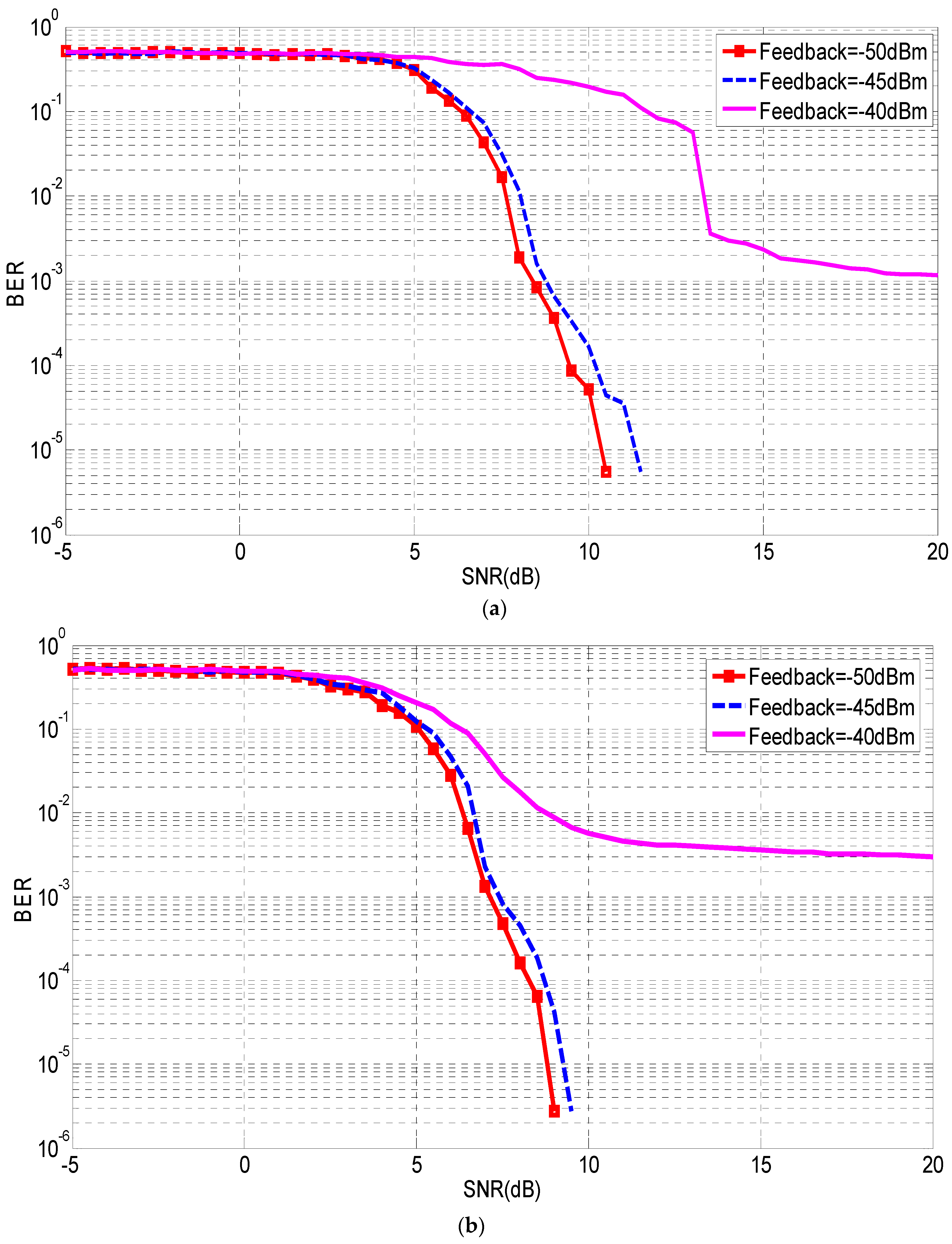
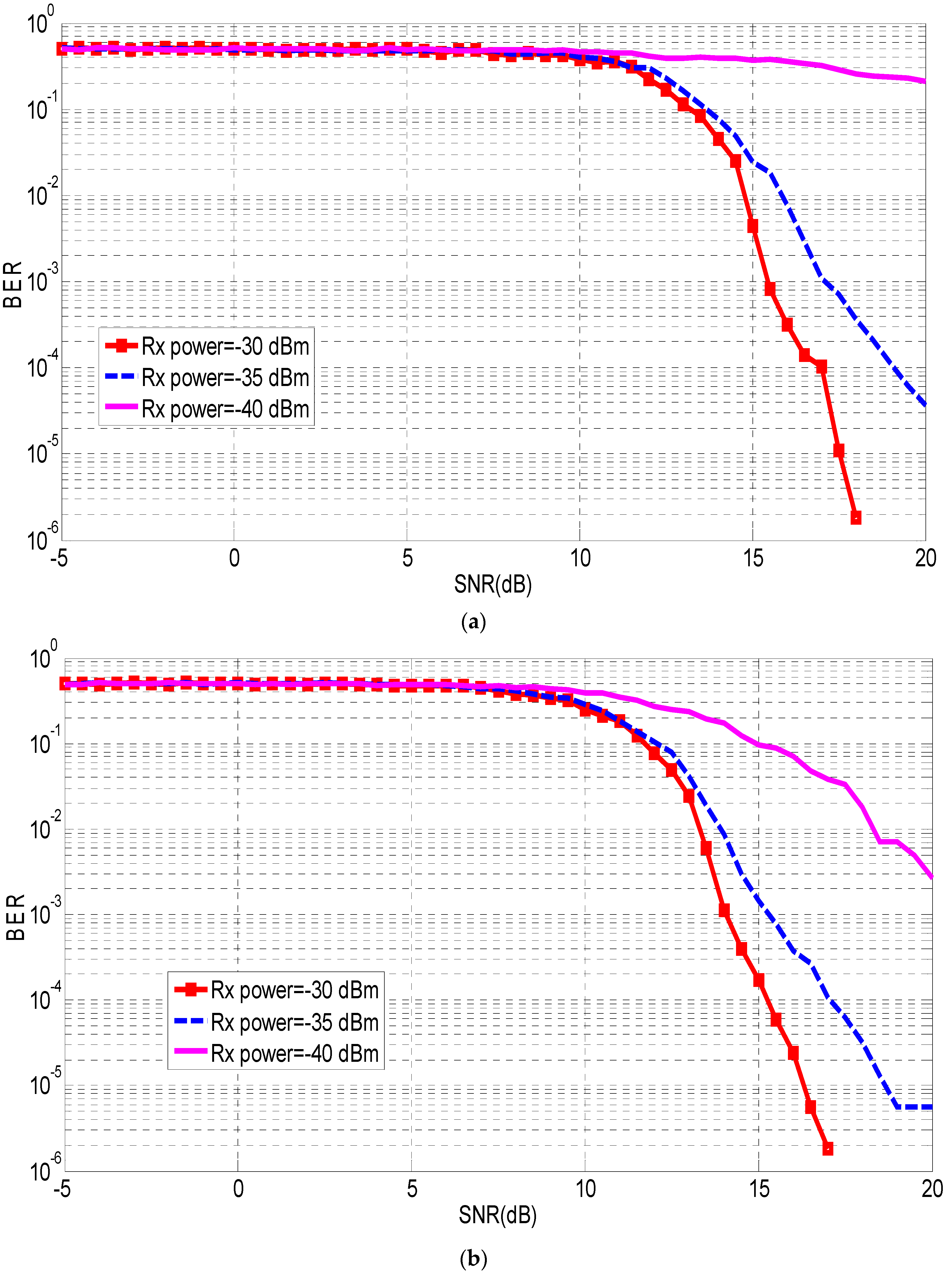
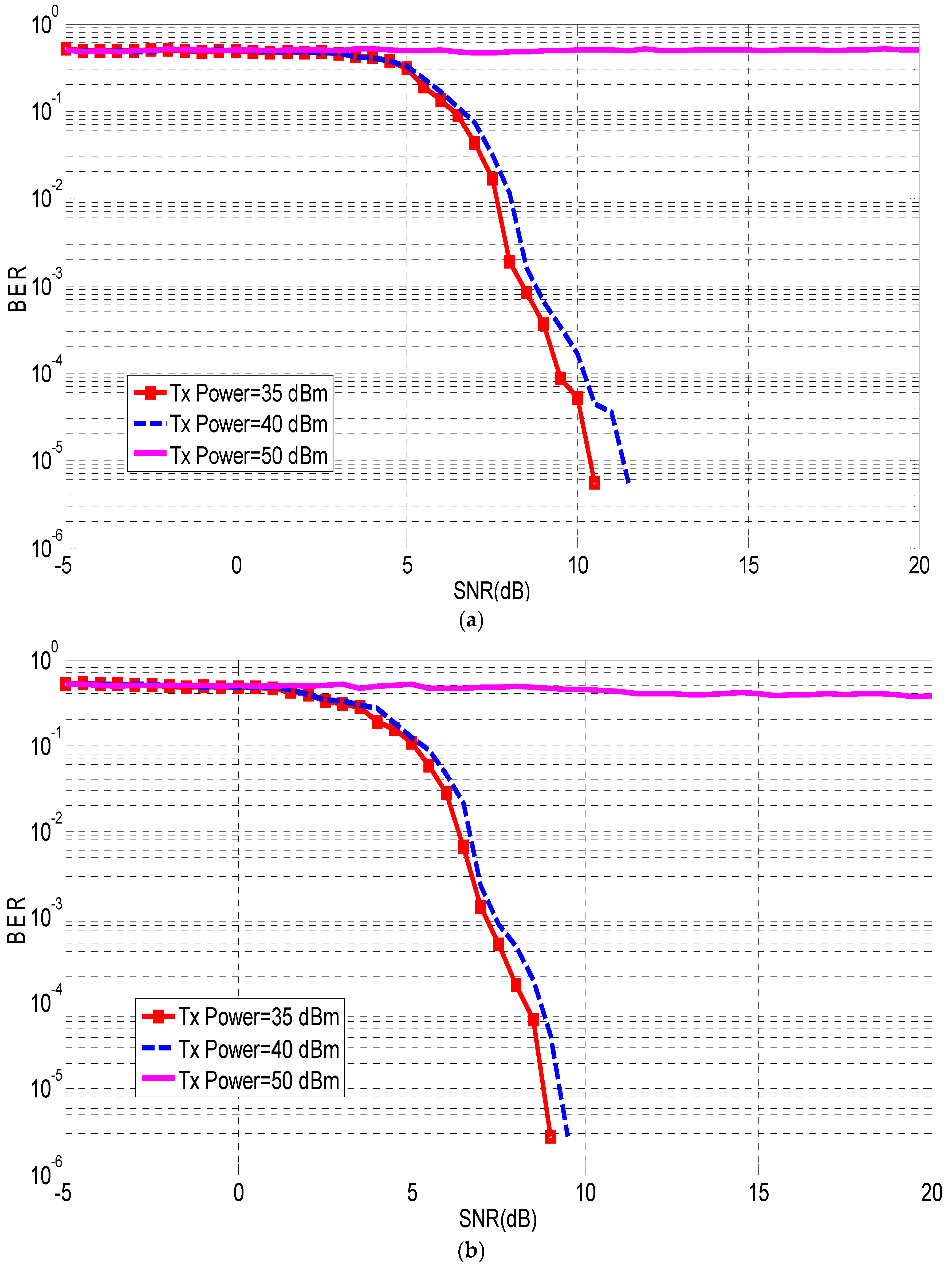
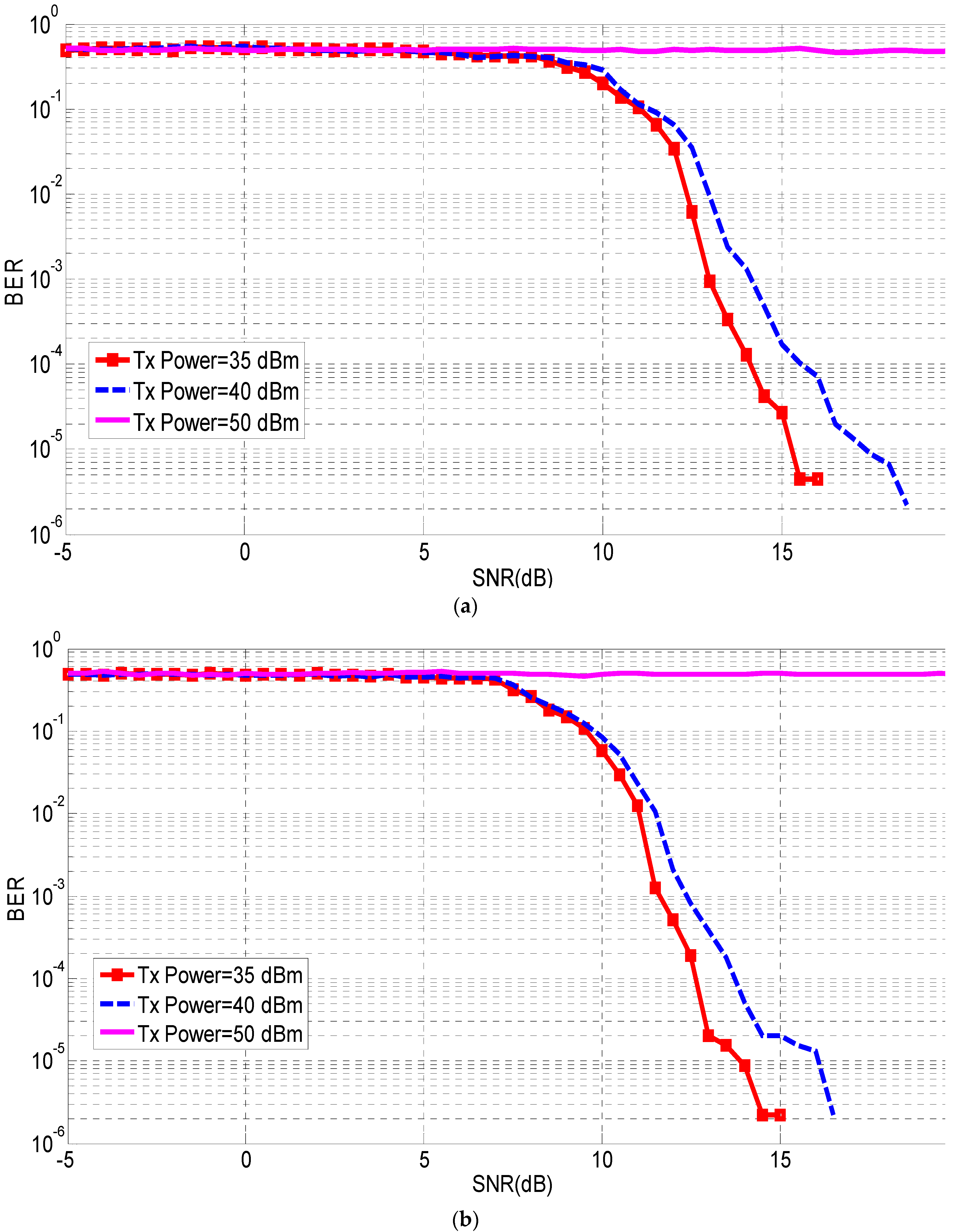
HIPERLAN/2 system has been modified to include the Alamouti technique as shown in Figure 3 for both two transmit antennas and one receiver antenna for both users. Besides, the method also applied when each user has two transmit antenna and two receive antenna. The transmit and receive antennas are assumed to be closely located. Each user has transmitters that transmit the symbols to the other user. The number of independent channels between the two users depends on the number of transmitting and receiving antennas. It is equal to the multiplication of the number of the antennas at the transmitter side by the number of the receive antennas. There are two groups of the channels in the modelling that are used; the first group is between the transmitter and the receiver within the same user, whereas the second group is between the transmitter of a user and the receiver of the other user.
Figure 3.
Modified HIPERLAN system.
More details of the channel box in Figure 3 is shown in Figure 4 and Figure 5 when the number of transmitting and receive antennas is varying. Figure 4 show the channels when the users have two transmit antennas and one receiver antenna, whereas Figure 5 shown the channels when each user has two transmit antennas and two receiver antennas. The channel modelling depends on the gain and attenuation block diagram, where the gain block will be used to model the channels between the transmit and the receive antennas within the same user, whereas the attenuator will be used to model the channels between the transmit and the receive antennas between the users. As a result, the receiver antenna of the first user received two signals; the signal transmitted by the same user and the signal transmitted by the other user in addition to the noise. It can be noticed from Figure 4 and Figure 5 that the transmitted symbols for the first user will be amplified by using a gain block. After that, the amplified symbols will be transmitted through the Rayleigh channel [18,19]. Meanwhile, the transmitted symbols by the second user will be attenuated by the same gain block. However, the amount of the gain will be less than one; in this case, the gain will be attenuation. The next stage is to send the attenuated symbols through other independent channels.
Figure 4.
The channels implementation for both users when each one has two transmit antennas and one receive antenna.
Figure 5.
The channels for both users when each one has two transmit antennas and two receive antennas.
After that, the output of the channel will be added together, and this will represent the input to the received antenna. It can be seen that at the user 1, the magnitude of the transmitted symbols by the same user will be higher than the magnitude of the transmitted signal by the other user, due to the attenuation and the gain. It should be noticed that the feedback knows the transmitted symbols and the channel state information (CSI) [18,19], because of the position of the transmitter and the receiver within the user.
5. Results
HIPERLAN/2 system shown in Figure 2 is tested when the 16QAM modulation is used. Figure 6 shows the symbols scattering for different stages: (a) at the transmitter side, (b) inside the channel, and (c) at the receiver side. It can be noticed that the channel has a significant effect on the transmitted symbols.
Figure 6.
Symbols scattering at (a) the transmitter, (b) the channel, and (c) the receiver.
The bit error rate of the HIPERLAN/2 system shown in Figure 3 utilizing different modulation schemes including 4-, 16-, 32-, and 64-QAM, in addition to the using the two types of Alamouti technique in terms of the number of antennas used at the transmit and the receive side is shown in Figure 7 and Figure 8. The HIPERLAN/2 performance when the user has two transmit antennas and one receive antenna and when each one has two antennas for the transmit and two for the receive, it can be noticed that, as the modulation complexity increases, the required SNR should be increased to achieve the same BER. In addition, the use of additional transmit antenna helps in achieving the same BER with lower SNR.
Figure 7.
HIPERLAN/2 performance when nTx = 2 and nRx = 1 for different modulation schemes.
Figure 8.
HIPERLAN/2 performance when nTx = 2 and nRx = 2 for different modulation schemes.
After that, a series of tests has been applied to the system to include the Alamouti technique as shown in Figure 3, where each user has two transmit antennas and one receiver antenna which are closely located, whereas in the other case, each one has two transmit antennas and two receiver antennas. The bit error rate of both users is tested depending on three parameters, which are: the transmitted power, the received power, and the feedback accuracy, all these parameters are tested with different modulation schemes. Figure 9, Figure 10, Figure 11 show the bit error rate in case the transmitted power and the received power are constant. It can be noticed that the feedback accuracy has a significant effect on the performance, as the feedback accuracy increases, the performance will be enhanced. At the same time, the feedback accuracy should be increased in the case of using a higher modulation scheme to improve the overall system performance.
Figure 9.
Modified HIPERLAN/2 performance, 16QAM, when feedback accuracy is varying (a) nTx = 2, nRx = 1, and (b) nTx = 2, nRx = 2.
Figure 10.
Modified HIPERLAN/2 performance, 32QAM, when feedback accuracy is varying (a) nTx = 2, nRx = 1, and (b) nTx = 2, nRx = 2.
Figure 11.
Modified HIPERLAN/2 performance, 64QAM, when feedback accuracy is varying (a) nTx = 2, nRx = 1, and (b) nTx = 2, nRx = 2.
On the other hand, HIPERLAN/2 system with Alamouti was also tested when the transmitted power and the feedback accuracy are constant and only the received power is varying, as shown in Figure 12, Figure 13, Figure 14. It is clear that the overall performance will be enhanced as the received power increased for all modulation schemes. Moreover, the increase of transmitted antennas helps in improving system performance.
Figure 12.
Modified HIPERLAN/2 performance, 16QAM, when received power is varying (a) nTx = 2, nRx = 1, and (b) nTx = 2, nRx = 2.
Figure 13.
Modified HIPERLAN/2 performance, 32QAM, when received power is varying (a) nTx = 2, nRx = 1, and (b) nTx = 2, nRx = 2.
Figure 14.
Modified HIPERLAN/2 performance, 64QAM, when received power is varying (a) nTx = 2, nRx = 1, and (b) nTx = 2, nRx = 2.
Finally, the proposed system was tested when the received power and the feedback accuracy are constant, and only the transmitted power is varying for different cases, as shown in Figure 15, Figure 16, Figure 17. It is obvious that the transmitted power affects the system performance, whereas at 50 dBm transmitted power, the system was not able to recover the original signal even when there is a high SNR. However, as the transmitted power decreases, the overall performance is improved. At the same time, less SNR will be enquired as the modulation scheme is reduced.
Figure 15.
Modified HIPERLAN/2 performance, 16QAM, when the transmitted power is varying (a) nTx = 2, nRx = 1, and (b) nTx = 2, nRx = 2.
Figure 16.
Modified HIPERLAN/2 performance, 32QAM, when the transmitted power is varying (a) nTx = 2, nRx = 1, and (b) nTx = 2, nRx = 2.
Figure 17.
Modified HIPERLAN/2 performance, 32QAM, when the transmitted power is varying (a) nTx = 2, nRx = 1, and (b) nTx = 2, nRx = 2.
6. Conclusions
Modifying the HIPERLAN/2 system to include and utilize a higher modulation scheme increases the data rate at the cost of increasing the required SNR that can achieve the same BER. In addition, introducing the MIMO system and transmit code diversity (Alamouti code) improves system performance, such as the data rate and capacity. The paper also suggested the use of full-duplex mode, where the transmit and the receive antennas are closely located. From the simulated results, it can be noticed that less SNR is required as the modulation scheme complexity is reduced, because the probability of recovering the received symbols will be increase as the modulation scheme complexity is decreased. Moreover, the results showed that the performance of the suggested system is heavily depended on the amount of the transmitted power, received power, and feedback accuracy. As the transmitted power increases, the system performance will be decreased when the other parameters are constant, and at the same time, when the transmitted power of the first user is 50 dBm, the receiver was not able to recover the transmitted signal from the other user because the amount of the transmitted power of the first user blocks the received signal. On the other hand, the increase of the received power helps in reducing the BER and improving the system performance when the other parameters are constant. Finally, the feedback accuracy is directly proportional to the system performance.
Author Contributions
Conceptualization, M.A.Y., I.A.S., O.I.A. and A.M.A.; methodology, A.M.A., M.A.Y. and O.I.A.; software, A.M.A., R.A.A.-A. and M.A.Y.; validation, R.A.A.-A., N.O.P., I.A.S. and Y.I.A.A.-Y.; formal analysis, R.A.A.-A., N.O.P., Y.I.A.A.-Y. and I.A.S.; investigation, M.A.Y., I.A.S., O.I.A., N.O.P. and Y.A.-Y.; resources, A.M.A., M.A.Y., R.A.A.-A., O.I.A. and Y.I.A.A.-Y.; data curation, M.A.Y., A.M.A. and R.A.A.-A.; writing—original draft preparation, A.M.A., M.A.Y. and R.A.A.-A.; writing—review and editing, O.I.A., I.A.S., A.M.A., M.A.Y., N.O.P. and R.A.A.-A.; visualization, M.A.Y., A.M.A., I.A.S. and O.I.A.
Funding
This project has partially received funding from the European Union’s Horizon 2020 research and innovation programme under grant agreement H2020-MSCA-ITN-2016 SECRET-722424.
Acknowledgments
Authors wish to express their thanks for the support provided by the innovation programme under grant agreement H2020-MSCA-ITN-2016 SECRET-722424.
Conflicts of Interest
The authors declare no conflict of interest.
References
- Paulraj, A.; Rohit, A.P.; Nabar, R.; Gore, D. Introduction to Space-Time Wireless Communications; Cambridge University Press: Cambridge, UK, 2003. [Google Scholar]
- Jafarkhani, H. Space-Time Coding: Theory and Practice; Cambridge University Press: Cambridge, UK, 2005. [Google Scholar]
- Abdulkhaleq, A.M.; Yahya, M.A.; McEwan, N.; Rayit, A.; Abd-Alhameed, R.A.; Ojaroudi Parchin, N.; Al-Yasir, I.Y.; Noras, J. Recent Developments of Dual-Band Doherty Power Amplifiers for Upcoming Mobile Communications Systems. Electronics 2019, 8, 638. [Google Scholar] [CrossRef]
- Larsson, E.G.; Stoica, P. Space-Time Block Coding for Wireless Communications; Cambridge University Press: Cambridge, UK, 2008. [Google Scholar]
- Wireless World; I.P.C. Business Press Limited: London, UK, 1974.
- Jasim, A.A.; Younus, K.M.; Ali, A.; Sayidmarie, K.H.; Alhaddad, A.; Abd-Alhameed, R.A. A simple self-interference cancellation technique for full duplex communication. In Proceedings of the 2017 Internet Technologies and Applications (ITA), Wrexham, UK, 12–15 September 2017; pp. 224–229. [Google Scholar]
- Nejdi, I.H.; Rhazi, Y.; Lafkih, M.A.; Bri, S. Designing Multiband Multilayered Microstrip Antenna for UMTS, ISM, Communication Satellite, HiperLAN and C-Band. In Proceedings of the 2018 International Symposium on Advanced Electrical and Communication Technologies (ISAECT), Kenitra, Morocco, 21–23 November 2018; pp. 1–8. [Google Scholar]
- Alam, M.S.; Yeh, K.M.; Islam, M.T.; Misran, N.; Hasbi, A.M. An EBG microstrip antenna for 5.4 GHz WLAN/HIPERLAN applications. In Proceedings of the 2012 IEEE Student Conference on Research and Development (SCOReD), Pulau Pinang, Malaysia, 5–6 December 2012; pp. 144–147. [Google Scholar]
- Gupta, A.; Tripathy, M.R.; Choudhary, V.; Ronnow, D. A compact four-element MIMO antenna for WLAN/WiMAX and HiperLAN applications. In Proceedings of the 2016 IEEE Annual India Conference (INDICON), Bangalore, India, 16–18 December 2016; pp. 1–4. [Google Scholar]
- Asokan, H.; Gopalakrishnan, S. A Miniaturized inductive—Loaded narrow strip wide band-notched ultra-wideband monopole antenna with dual-mode resonator. AEU Int. J. Electron. Commun. 2018, 86, 125–132. [Google Scholar] [CrossRef]
- Zid, M.B. Recent Trends in Multi-user MIMO Communications; IntechOpen: London, UK, 2013. [Google Scholar]
- Abdulkhaleq, A.M.; Ali, N.T.; Abd-Alhameed, R.A.; Sayidmarie, K.H.; See, C.H.; Noras, J.M.; Excell, P.S. Noise cancellation for compact MIMO systems. In Proceedings of the 5th International Conference on Internet Technologies and Applications, Wrexham, UK, 10–13 September 2013. [Google Scholar]
- Wireless Communications; Tata McGraw-Hill Education: New York, NY, USA, 2005.
- Esli, C.; Ozgul, B.; Delic, H. Space-frequency coded HIPERLAN/2. IEEE Trans. Consum. Electron. 2004, 50, 1162–1168. [Google Scholar] [CrossRef]
- Esli, C.; Ay, G.; Ozgul, B.; Delic, H. Space-frequency coding for the HIPERLAN/2 standard. In Proceedings of the 12th IEEE Mediterranean Electrotechnical Conference (IEEE Cat. No.04CH37521), Dubrovnik, Croatia, 12–15 May 2004; Volume 442, pp. 445–448. [Google Scholar]
- Moubadir, M.; Badaoui, I.; Touhami, N.A.; Aghoutane, M.; Ouahabi, M.E. A new circular polarization dual feed microstrip square patch antenna using branch coupler feeds for WLAN/HIPERLAN applications. Procedia Manuf. 2019, 32, 702–709. [Google Scholar] [CrossRef]
- Kruys, J. HIPERLAN, applications and requirements. In Proceedings of the [1992 Proceedings] Third IEEE International Symposium on Personal, Indoor and Mobile Radio Communications, Boston, MA, USA, 19–21 October 1992; pp. 133–138. [Google Scholar]
- Giordano, A.A.; Levesque, A.H. Modeling of Digital Communication Systems Using SIMULINK; Wiley: Hoboken, NJ, USA, 2015. [Google Scholar]
- Rao, K.D. Channel Coding Techniques for Wireless Communications; Springer India: Berlin, Germany, 2015. [Google Scholar]
© 2019 by the authors. Licensee MDPI, Basel, Switzerland. This article is an open access article distributed under the terms and conditions of the Creative Commons Attribution (CC BY) license (http://creativecommons.org/licenses/by/4.0/).