Abstract
A future capability in dynamic mesoscale materials science is needed to study the limitations of materials under irreversible and extreme conditions, where these limitations are caused by nonuniformities and defects in the mesoscale. This capability gap could potentially be closed with an X-ray free-electron laser (XFEL), producing 5 × 10¹⁰ photons with an energy of 42 keV, known as the Matter–Radiation Interactions in Extremes (MaRIE) XFEL. Over the last few years, researchers at the Los Alamos National Laboratory have developed a preconceptual design for a MaRIE-class XFEL based on existing high-brightness beam technologies, including superconducting L-band cryomodules. However, the performance of a MaRIE-class XFEL can be improved and the risk of its operation reduced by investing in emerging high-brightness beam technologies, such as the development of high-gradient normal conducting radio frequency (RF) structures. Additionally, an alternative XFEL architecture, which generates a series of high-current microbunches instead of a single bunch with uniformly high current along it, may suppress the most important emittance degradation effects in the accelerator and in the XFEL undulator. In this paper, we describe the needed dynamic mesoscale materials science capability, a MaRIE-class XFEL, and the proposed microbunched XFEL accelerator architecture in detail.
1. Introduction
An important emerging materials science frontier is in mesoscale science, and especially its time-dependence or dynamics. The mesoscale scale length (typically micrometers to millimeters) is where material nonuniformities and defects appear and where multiple length scales combine to create emergent phenomena. “Dynamic” refers to materials’ performance under irreversible and extreme conditions. Mesoscale effects can dominate the determination of materials’ properties, going from ideal atomic materials to bulk materials used in engineered devices, see Figure 1. At this scale, the heterogeneous physics of dislocation or defect nucleation, growth, and coalescence takes place. As examples, local defects can be driven by spall damage, by the creation of void and gas bubbles due to fission or irradiation, or by shock-driven phase transformations, plasticity, and twinning. Understanding how these heterogeneities form, especially under extreme conditions of temperature, pressure, or radiation, will impact future science, societal, and security missions, ranging from ensuring that spacecraft taking data in the Jovian radiation belts survive [1] to learning how to build materials for future fusion reactors such as the International Thermonuclear Experimental Reactor (ITER) [2].
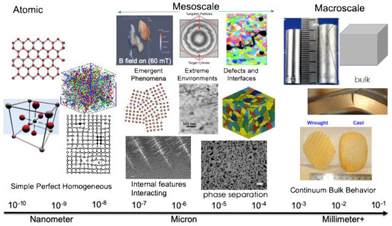
Figure 1.
US Department of Energy illustration comparing the mesoscale to both the atomic scale and the macroscopic bulk material. Understanding the mesoscale is important for discovering the linkages of materials’ properties from microstructure and processing to performance. Enhancing production of materials and their performance is particularly important in extreme environments.
The US Department of Energy has formally recognized a mission need and capability gap for a Dynamic Mesoscale Materials Science Capability (DMMSC). The Los Alamos National Laboratory (LANL) has led the effort to define and design a solution for this need. A DMMSC seeks to probe inside multigranular samples of condensed matter that can be effectively probed with subgranular resolution and represent bulk performance properties. With grain sizes of tens of microns, “multigranular” means ten or more grains, and hence, samples of a few hundred microns to a millimeter in thickness. Along with other potential tools, an X-ray free-electron laser (XFEL) can be valuable for DMMSC, providing the ability to image samples with coherent X-ray diffractive imaging [3]. Researchers at LANL have scoped out a potential XFEL for this mission, known as the Matter–Radiation Interactions in Extremes (MaRIE) XFEL. For medium-Z elements, such an XFEL would have to produce photon energy of 42 keV and above to penetrate samples of material up to a hundred microns (see Figure 2). Such a high photon energy also reduces the absorbed energy by an atom during its exposure to the X-rays and allows multiple measurements on the same sample before it blows apart, also shown in Figure 2.
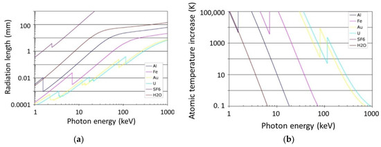
Figure 2.
(a) e-folding radiation length: The photon energy needs to be ~40 keV or higher to penetrate through mm-sized samples to study the properties of mesoscale materials. (b) Heating per atom for 1011 photons in a sample 2-radiation lengths thick—importantly, the heating per atom in the sample drops with increasing energy. Photon energies of 40 keV and higher will ensure the sample is not blown apart when imaged, allowing for multiple views during dynamic events.
An XFEL with these parameters is positioned to fill a critical gap in materials testing, with a length scale between the macroscale of LANL’s Dual-Axis Radiographic Hydro Test (DARHT) [4] and the atomic scale of the Lawrence Livermore National Laboratory’s National Ignition Facility (NIF) [5], see Figure 3.
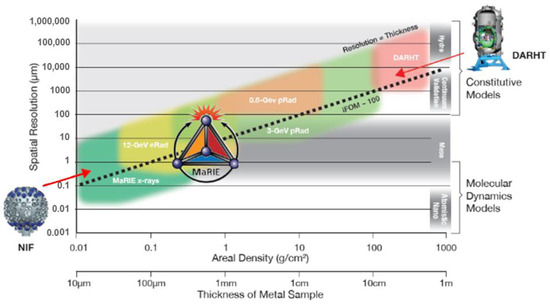
Figure 3.
Plot of the length scales of resolution and materials’ thickness that various existing and proposed US Department of Energy tools can achieve. The atomic scale of National Ignition Facility (NIF) samples is on the left side of the plot, and the device scale objects of Dual-Axis Radiographic Hydro Test (DARHT) are on right. Areal density for radiography can be approximately converted to a length scale, assuming 10 g/cm3 density of metal. The imaging figure-of-merit (iFOM), which is the ratio of image field-of-view (total thickness of sample) divided by the possible diagnostic spatial resolution, is the lines of constant upward slope. To get resolution in the mesoscale requires 0.1–tens-of-micron resolutions. A 0.8 GeV proton radiography (pRad) facility currently exists at the Los Alamos Neutron Science Center (LANSCE) accelerator at LANL [7]. A 3 GeV pRad facility has been proposed, and a 12 GeV electron radiography (eRad) facility is envisioned to be part of the Matter–Radiation Interactions in Extremes (MaRIE) X-ray free-electron laser (XFEL) facility, which would nominally be driven by a 12 GeV electron beam.
An XFEL such as MaRIE can be built with conventional accelerator technology [6]. However, we have recognized that emerging novel high-brightness electron beam technologies have the potential to both reduce the cost of a high-energy XFEL and reduce the risk of it not meeting its design goals. There are two specific emerging high-brightness beam technologies we have considered to improve the performance of MaRIE-class XFELs: (1) High-gradient cyrocooled normal conducting RF; and (2) an alternative accelerator architecture generating a microbunched beam instead of a single, high-current electron bunch. In this paper, we focus on the second of these technologies and show why this approach may significantly reduce the risk of a high-energy XFEL.
The structure of this paper is the following. In Section 2, we describe the parameters of the proposed MaRIE XFEL and the challenges in achieving these parameters. Section 3 provides a direct comparison between a conventional XFEL architecture and one based on generating a microbunched beam. Significantly, preliminary studies indicate that a microbunched beam will provide essentially the same XFEL performance while suppressing the most important beam instabilities limiting XFEL performance. In Section 4 we provide the underlying theory for a microbunched beam and an application of the theory to a MaRIE-class XFEL.
2. The MaRIE XFEL Concept
Modeling the imaging of mesoscale phenomena with an XFEL has provided the following functional requirements for a MaRIE-class XFEL to address mesoscale materials science [8]:
- 42 keV X-ray energy;
- 5 × 10¹⁰ photons per X-ray pulse;
- 0.02% spectral bandwidth of the X-rays.
In addition, to study certain dynamic effects, up to 100 X-ray pulses may be required, with up to 20 pulses within a single 100 nsec window.
The MaRIE XFEL concept is to use a 12 GeV, 100 pC electron bunch, compressed to a peak current of 3 kA to generate the 42 keV X-rays. A beam energy of 12 GeV has been chosen as it is resonant at that X-ray wavelength () with about as short an undulator period as practical (, similar to that used for the Linac Coherent Light Source (LCLS) XFEL [9] at the SLAC National Accelerator Laboratory). The normalized undulator parameter K is relatively low for a normal conducting hybrid undulator with this period, about 0.86 root mean square (rms).
In Figure 4, we show results from a series of Ming Xie parameterizations [10] of XFEL performance, where predicted X-ray flux versus electron beam quality is shown for a continuous (i.e., time-independent) 3 kA, 12 GeV beam (time-dependent effects will tend to decrease the average power by about 10%–15%). To achieve a flux of 5 × 10¹⁰ photons per X-ray pulse, an electron beam emittance of about 0.2 μm and an energy spread of about 0.015% would be needed, indicated by the blue star. While these numbers are reachable, they are beyond the current state-of-the-art of high-brightness electron beams. For calibration with X-ray power, 10 GW is equivalent to the requirement of 5 × 10¹⁰ photons per X-ray pulse for a 100 pC bunch compressed to 3 kA.
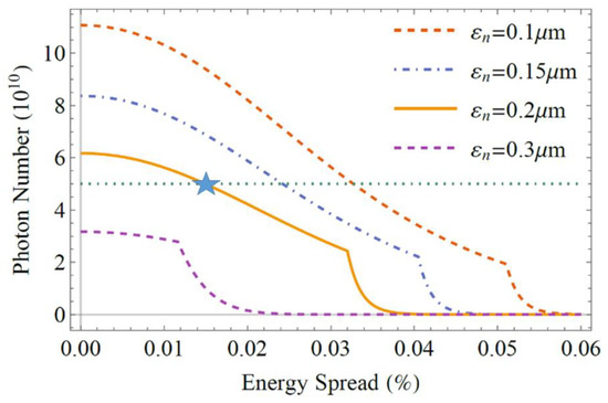
Figure 4.
Idealized estimates of XFEL performance using the Ming Xie parameterization showing the baseline MaRIE XFEL performance at 12 GeV as a function of electron bunch energy spread and emittance for an undulator of a fixed 100 m length. The photon power numbers from this plot should be degraded by about 10%–15% due to time-dependent effects, which indicates that the beam emittance and energy spread really need to be a bit better than 0.2 μm and 0.015%, respectively.
A preconceptual MaRIE XFEL design has been developed to achieve these numbers. Note that the X-ray flux is somewhat more sensitive to emittance than energy spread near the MaRIE operating point (i.e., an increase of a factor of two in emittance more than halves the flux; while an increase of a factor of two in energy spread less than halves the flux) which has motivated a design that sacrifices energy spread at the expense of decreasing the emittance.
The preconceptual design starts with a highly optimized photoinjector [11] (based on the Photo-Injector Test facility at Zeuthen (PITZ) photoinjector design [12] generating a 100 pC electron bunch charge) but otherwise conventional accelerator technology [13]. Specifically, it assumes the use of superconducting Teraelectronvolt Energy Superconducting Linear Accelerator (TESLA)-style 1.3 GHz cyromodule accelerator structures operating at the International Linear Collider (ILC) design gradient of 31.5 MV/m. To achieve low transverse emittances, the cathode radius is very small, about 0.1 mm, leading to a thermal emittance of about 40 nm and a geometric emittance of about 60 nm, for a total emittance of about 75 nm. The resulting low bunch current (about 7 A, with a full-width half maximum (FWHM) bunch length of about 15 psec) requires a total bunch compression of about 450 to achieve a peak current in the undulator of 3 kA. While this preconceptual design is traceable to mature technologies, it still contains high risk. For example, this high compression ratio will likely drive the microbunching instability gain [14] to unacceptably high levels. Also, the large Q-factor of superconducting cyromodules (which could be as high as a few times 1010) may not have enough damping to suppress the long-range wakefields for the required multipulse format [15]. Moreover, the operating point indicated by Figure 4 is in a location with high slope—any increase in either beam emittance or energy spread will significantly degrade the X-ray flux.
We are confident that increasing the energy of the electron beam will always reduce risk, and that a MaRIE-class XFEL can be built and reliably operated at a sufficiently high energy. Since the normalized Pierce FEL gain [16] is given by
where γ is the relativistic mass factor of the beam after acceleration, σ is the rms transverse beam size, I is the bunch current, IA is about 17 kA, and JJ is a factor close to unity due to the figure of 8 motion of the electrons in their own frame of reference, the gain can always be increased enough by increasing the beam energy (i.e., γ) to overcome any energy spread and emittance limitations. Note that the gain is maximized at any energy with an undulator strength of , which is achievable at high energies as the undulator period becomes longer. It is worth noting that the energy diffusion from the quantum fluctuations of the incoherent synchrotron radiation (ISR) [17] decreases with increasing energy for a fixed X-ray wavelength and undulator parameter K and does not become problematic. The energy diffusion is given by
where Bp is the peak magnetic field in the undulator and Lund is the undulator length. Since the undulator magnetic field [16] is
the ISR-induced energy spread decreases inversely with increasing beam energy.
Increasing the accelerator energy to ensure the XFEL design is robust can be an unnecessarily expensive solution. This issue, among others, has motivated the study of alternative MaRIE XFEL architectures and accelerator technologies. For example, it is possible that cyrocooled, but normal conducting, high-gradient standing-wave accelerator structures [18] will reduce the risk of emittance dilution due to their higher gradient, plus its highly damped wakefields may allow the multipulse X-ray format. Modeling has already suggested that a gun based on that technology could increase the bunch current in a photoinjector to 20 A while maintaining the same low emittance (<0.1 μm) [19], thereby significantly reducing the required compression ratio to only 150:1.
In the numerical examples of Section 4, we will assume that such an advanced photoinjector can be operated and that the XFEL accelerator is based on C-band (about 6 GHz), high-gradient (about 120 MV/m accelerating gradient), normal-conducting RF structures.
3. Comparison of XFEL Accelerator Architectures
3.1. Conventional XFEL Architecture
A conventional XFEL accelerator design is shown in Figure 5, with an electron gun, three accelerator (linac) sections (L1–L3), and two bunch compressors (BC1 and BC2) stationed between the linac sections. The bunch compressors are needed to increase the peak current from that generated at the electron gun to that needed in the undulator to produce the X-rays efficiently, which is about 3 kA. Nominal values for a 100 pC electron bunch would be, for example, an initial peak current of 20 A, a peak current of about 300 A after BC1 (i.e., a compression ratio of 15:1), and a peak current of about 3 kA after BC2 (i.e., a compression ratio of 10:1). Figure 6 shows how the BCs actually compress the bunch—the preceding linac section imposes an energy “chirp” along the bunch such that the electrons at the back of the bunch have higher energy than those at the front. The compressor magnets ensure that higher energy particles take a shorter path through the element and, as a result, the electrons at the tail of the bunch “catch-up” to those in the front, thus compressing the bunch length.
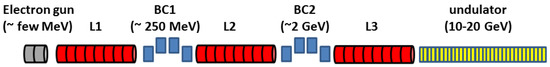
Figure 5.
Conventional XFEL beamline elements with nominal XFEL parameters: The (grey) photoinjector generates about a 2 psec (rms), 100 pC bunch; (red) linac sections accelerate the electron bunch; (blue) bunch compressors compress the bunch length from about 2 psec to about 130 fsec and then from about 130 fsec to about 13 fsec; (yellow) the beam generates X-rays in a planar undulator.
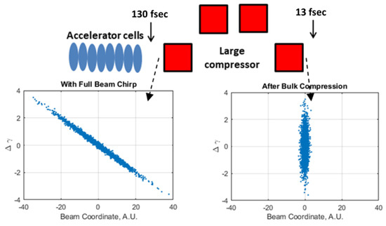
Figure 6.
Beam-line elements and corresponding energy vs. longitudinal position plots for the final bunch compression in a standard XFEL accelerator design.
The conventional XFEL architecture is plagued by three important beam degradation phenomena which limit its ultimate performance: coherent synchrotron radiation (CSR) [20,21], the undulator resistive wall wake (URWW) [22], and the microbunching instability (MBI) [23,24]. CSR degrades the beam’s emittance in a bunch compressor from the large electric fields that arise from normal synchrotron radiation, with wavelengths comparable to (and longer than) the bunch length such that the radiation is coherent. The CSR effect scales as the bunch charge divided by the compressed bunch length to the 4/3 power and is a fundamental limitation of conventional XFEL designs. The URWW degrades the beam’s energy spread in the undulator as different electrons lose different amounts of energy due to the wakefields of all the other electrons that come earlier in the bunch, due to the small radius of the beam pipe walls inside the undulator. While the electrons lose energy at a constant rate from the URWW within the undulator, tapering the undulator can only keep part of the electron bunch resonant, as the rate is a function of position within the bunch itself. The change in electron energy as a function of position s within the bunch at the end of the undulator due to the URWW for nominal MaRIE parameters is shown in Figure 7 along with a plot estimating the decrease in the amount of X-rays due to the increased energy spread of the bunch. The URWW can easily dominate the electrons’ energy losses. For a 13.64 GeV, 250 pC, 3 kA electron bunch at LCLS, the average energy loss per electron from the URWW is about 40 MeV, larger than both the spontaneous radiation (16 MeV, and about the same for every electron) and lasing (about 10 MeV) [25].
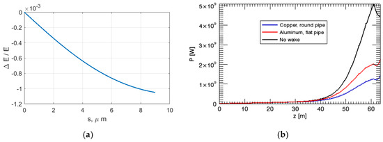
Figure 7.
(a) The change in electron energy at the end of the undulator due to the undulator resistive wall wake (URWW) as a function of position within the bunch for a 12 GeV, 3.3 kA beam in a pipe with a gap of 0.53 cm. (b) The decrease in X-ray power is more than a factor of 2 as a result of the URWW (for MaRIE parameters). Note that the spread of electron energies can reach 0.1% (compare with Figure 4).
The MBI is an energy spread growth mechanism that amplifies shot noise in the original beam distribution when two bunch compressors are used—the very small energy modulation induced from the beam’s original tiny variations in density leads to larger density fluctuations after BC1 which, in turn, generates a much larger energy spread as the beam travels to BC2. BC2 transforms the increased energy spread into even larger density fluctuations that can generate very large energy spreads as the beam is accelerated further, degrading the lasing. To suppress MBI, conventional XFELs use a “laser heater” to impose a random energy spread on the beam [26], which washes out the density fluctuations after the BC1, but at the cost of an increased beam energy spread. Figure 8 compares the final energy spread from MBI theory to that from detailed particle simulations with the numerical tool ELEctron Generation ANd Transport (ELEGANT) [27] for various amounts of laser heating, for a total compression ratio of about 150:1. For MaRIE-class parameters (from Figure 4, a maximum energy spread of about 1.8 MeV is allowed at a beam energy of 12 GeV), the energy spread induced by the laser heater reduces the design headroom significantly. The green curve shows the energy spread from space-charge forces in L3; and the red from space-charge forces in both L2 and L3. Importantly, nearly all of the induced energy spread arises in L3 because of the increased beam current after BC2. Ideally, BC2 would be placed at the accelerator’s final energy, however, in practice, that would lead to an excessively large compressor momentum compaction , which would, in turn, drive excessive CSR effects.
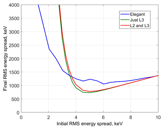
Figure 8.
ELEctron Generation ANd Transport (ELEGANT) simulations agree well with optimal laser heater energy predicted by theory. Minimum energy spread is somewhat greater in ELEGANT simulations—this is likely due to extra physics effects (incoherent synchrotron radiation (ISR), coherent synchrotron radiation (CSR), changing transverse beam size) that cannot be easily separated from microbunching.
To illustrate the results of Figure 8, the corresponding final beam longitudinal phase space (electron energy versus position within the bunch) is shown for a total compression ratio of 150:1 in Figure 9 for the cases of no laser heater (a), the optimum amount of laser heating (b), and too much laser heating (c), where the vertical axis is the particles’ energy deviation in units of the mass (or Δγ).
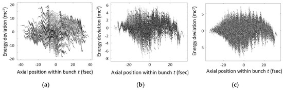
Figure 9.
(a) Without a laser heater, the particles’ energy spread is about 5 MeV. (b) The optimal laser-heater-induced energy spread leads to a final rms energy spread of about 1 MeV (which, from Figure 4, is beginning to degrade X-ray flux). (c) Extra induced energy spread from the laser heater just adds to the final rms energy spread. Figures from [28].
3.2. Microbunched XFEL Architecture
We have investigated the architecture shown in Figure 10 as a possible alternative accelerator architecture for a MaRIE XFEL [29], where a laser modulator and small compressor is used to generate a train of high current (i.e., 3 kA) bunches instead of a single, longer one.
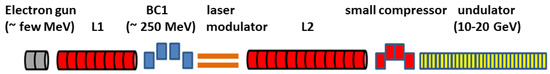
Figure 10.
Alternative microbunching architecture.
The laser-modulator/small-compressor architecture was originally proposed by Zholents [30] in the context of enhanced self-amplified spontaneous emission (eSASE), to increase the peak current of an electron bunch in a conventional XFEL architecture to overcome lasing limitations from having too large an emittance. Here, alternatively, we are using this architecture to generate a microbunched beam instead of increasing the peak current of a single bunch and this mechanism is more properly described as laser assisted bunch compression (LABC). In contrast to Figure 6, the LABC microbunching mechanism is illustrated in Figure 11. While the small compressor is shown at the same energy as the laser modulator in Figure 11, in practice, it is likely to be placed at the electron beam’s final energy, as shown in Figure 10, to suppress space-charge-induced energy spread within each microbunch and to minimize any microbunch instability effects. It is important to point out that the LABC section can be placed at the final beam energy because the required momentum compaction of the small compressor (R56) is small and there is no residual post-compression chirp to remove.
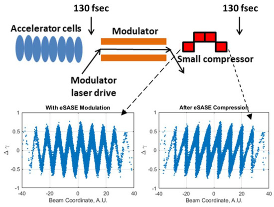
Figure 11.
Beam-line elements and corresponding energy vs. longitudinal position plots for an XFEL accelerator design with the microbunching architecture replacing the final bunch compression (Figure 6). Note that the final bunch shape has many small bunches (but with high peak current) over a much longer length than the compressed beam in Figure 6.
An example of a microbunched beam is shown in Figure 12 for illustrative purposes. Here, the 150 fsec long bunch consists of 70, 3 kA bunches, each separated by 1 μm. Keeping the rms bunch size large suppresses the CSR effect, due to the scaling of bunch charge divided by the bunch length to the 4/3 power, and also suppresses the URWW (Figure 13). Equally important, we expect that the MBI gain will be suppressed without a second bunch compressor at low energy. In addition, note that since the necessary energy-phase correlation for a second bunch compressor is not required, this architecture does not require accelerating the beam off-crest before compression (as L2 would need to be operated in Figure 5), leading to more efficient use of the RF with reduced capital and operating costs.
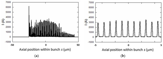
Figure 12.
Illustration of microbunching the electron beam. Here, the overall 150 fsec long bunch (a) consists of about 70, 3 kA microbunches separated by 1 μm as an example (shown in the blown-up in (b)).
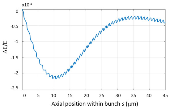
Figure 13.
The change in electron energy at the end of the undulator due to the URWW as a function of position within the bunch for the case of the longer, microbunched beam. Note the maximum energy depression is about a factor of 5 less than that shown in Figure 7a.
4. Background Theory and Application
While the LABC architecture is inspired by the eSASE architecture, its goal is different. The eSASE architecture is focused on generating as high a current spike as possible to overcome emittance limitations for SASE. LABC, instead, aims to generate a train of electron bunches with peak currents the same as used typically for SASE, but with a low average current such that long range CSR and URW wakes and the microbunching instability are efficiently suppressed. Also, it provides an opportunity for more efficient on-crest acceleration.
4.1. Idealized Background Theory for a Single Modulation Wavelength
The LABC formation of microbunches is a two-step process that may have acceleration between the steps. During the first step, electrons enter one or more modulation undulators, each with a period and undulator parameter ) driven by an external laser, where is the peak magnetic field. For synchronous modulation, the energy of the beam is matched to the undulator period and strength and the wavelength of the laser such that
where we allow the electron beam to propagate with an angle θ relative to the laser, which can be used to reduce the modulator period if the modulation is done at high energy. The interaction of electrons with a resonant laser field results in the electron energy modulation , with an amplitude of
where is the peak laser power, , is the number of undulator periods of the modulator, and [30]. In the second step, electrons enter a magnetic chicane with momentum compaction factor that converts energy modulation into a current modulation.
First, consider the use of a single modulation undulator. The longitudinal distribution function of an initially uniform electron beam with an initial Gaussian beam energy distribution before energy modulation before the laser becomes
in this two-step process, where ( is the laser wavenumber) and are scaled coordinates of the electrons, and are the scaled parameters of the modulation and compression steps, is an average energy, and is the rms energy spread. We can describe the compression of the beam as [31]
where is the local compression at a longitudinal coordinate inside the beam, n is the harmonic number, and is the bunching factor of the n-th harmonic.
We can use the definitions of the normalized laser modulation A and normalized momentum compaction B to calculate the compression ratio, shown as a color in the heat plot in Figure 14a. The dashed black line corresponds to a compression ratio of 10, the dashed yellow line corresponds to the condition of peak current (i.e., , which is the design point for eSASE), and the dashed green line corresponds to the LABC condition such that , which gives a flat-top microbunch. Starting at the bottom left corner on the dashed black line, 10× compression is characterized by excessive modulation and weak compression until an up-right compression is achieved at the eSASE condition labeled by the left-most red cross. As one continues along the dashed black line, 10× compression is characterized by weak modulation that demands a large R56. The LABC parameters labeled by the right-most red cross correspond to the boundary between a single microbunch and a double microbunch current distribution. The difference in the compressed current profile between the nominal eSASE and LABC conditions is shown in Figure 14b; and the compressed longitudinal phase spaces for the two conditions are shown in Figure 15 15a,b, illustrating the key difference between the eSASE and LABC conditions. For the eSASE condition (Figure 15a), the microbunch current is maximized; while for the LABC condition, the bunch is actually overcompressed where higher-energy electrons have overtaken slower-energy electrons. It is worth noting that the peak currents from both conditions are the same (Figure 14b) because both conditions correspond to a compression ratio of 10 (the dashed black line in Figure 14a), with a significantly lower normalized laser modulation A for the eSASE condition. If the normalized laser modulation was the same (), a higher compression ratio would be achieved for the eSASE condition (as the dashed yellow line lies above the dashed black line in a region of higher compression in Figure 14a). Thus, the key trade-off between the eSASE and LABC conditions is that a flatter bunch with more total trapped charge for the same compression ratio can be achieved with the LABC condition, but at the cost of a higher required laser modulation which will lead to a higher final beam energy spread.
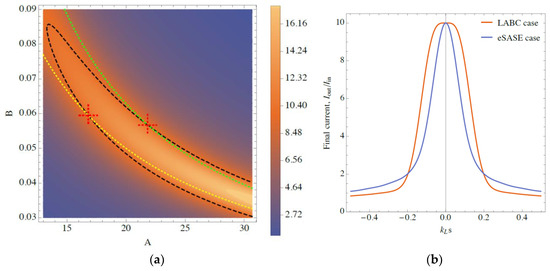
Figure 14.
(a) Compression ratio at coded by color using the scale on the right, as a function of normalized laser modulation A and normalized momentum compaction B. (b) The targeted laser assisted bunch compression (LABC) compression, corresponding to the dashed green line in (a), has a broader and flatter compressed current distribution than the targeted enhanced self-amplified spontaneous emission (eSASE) compression (highest compression, or AB = 1), corresponding to the dashed yellow line in (a).
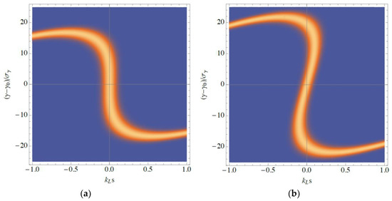
Figure 15.
(a) Longitudinal phase space for eSASE leading to the maximum compressed peak current. (b) Longitudinal phase space for LABC where the second derivative of the current vanishes at the center of the bunch.
The LABC optimization can be further illustrated in Figure 16a,b, where the distribution FWHM (relative to the compression at the center of the bunch ) and the fraction of charge within that FWHM are plotted along the 10× compression contour. In both plots, the left-most blue circle indicates the eSASE condition and the right-most blue circle indicates the LABC condition. Note that the microbunch is wider with a higher fraction of captured charge for the LABC condition relative to the eSASE condition. As the microbunch length has to be as long as the slippage through the undulator to avoid XFEL performance degradation, the narrower width of the eSASE microbunch would require a longer laser wavelength for the energy modulation. Also note that the LABC condition is a trade-off between microbunch length and fractional captured charge—movement along the 10× compression contour in either direction either reduces one or the other.
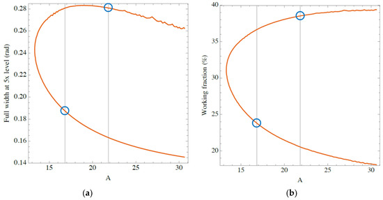
Figure 16.
(a) Full-width half maximum (FWHM) (5× compression) relative to the peak current at the center of the microbunch (10× compression) along the 10× compression contour, shown in Figure 14a. (b) Fraction of the bunch charge captured within the microbunches’ FWHMs.
A sinusoidal energy modulation of the form imposed on a temporally uniform distribution of electrons will lead to an rms energy spread of added in quadrature to the initial rms energy spread of the electrons (which can be ignored for large A). Figure 17 shows that the rms energy spread at the center of the microbunch for the case is a bit smaller, roughly . Some care should be used when considering the scaling curves in Figure 4 as their underlying simulations assumed a Gaussian energy distribution—while the energy distribution for the LABC microbunch is flatter as a function of energy, the rms energy spread is still the best figure of merit.
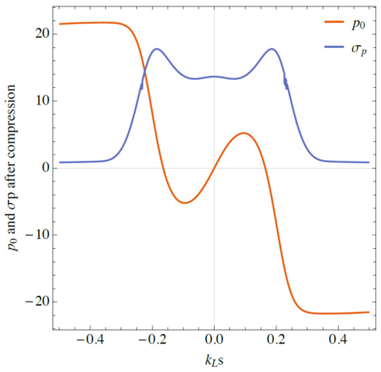
Figure 17.
Slice rms energy spread (blue line) and slice mean energy (red line) for the LABC compressed distribution, shown in Figure 15b, as a function of axial position within the microbunch.
4.2. Other LABC Considerations
Hemsing [31] has approximate expressions that can be used to describe the maximum compression ratio and the FWHM length [31], which we can use for estimating the final energy spread. (These estimates are pretty good, for example, would imply a compression ratio of 11.7:1, within 20% of the actual amount from Figure 8.) These approximate expressions lead to a final compressed energy spread of about
In comparison, the final energy spread for a conventional XFEL architecture is , where is the energy spread induced by the laser heater. As a relatively larger thermal energy spread is needed to suppress the microbunch instability in a conventional XFEL architecture, the LABC architecture has the potential to lead to a significantly lower final energy spread.
Figure 18 shows a typical generation of X-ray flux from a series of microbunches, using GENESIS [32], where the smooth Gaussian curves correspond to the current injected into the GENESIS simulation with the instantaneous beam current noted by the right vertical axis. In addition, the spiky curves that are filled-in correspond to the instantaneous X-ray power estimated by GENESIS with the level of the power noted by the left vertical axis. Each separate microbunch and associated X-ray generation is distinguished by a unique color. Here, the laser wavelength is and the current spikes are about 3.5 kA, with about a factor of 6 compression. We see that the coherence length is less than the microbunch length , where is the XFEL saturation length and is the undulator wavelength.
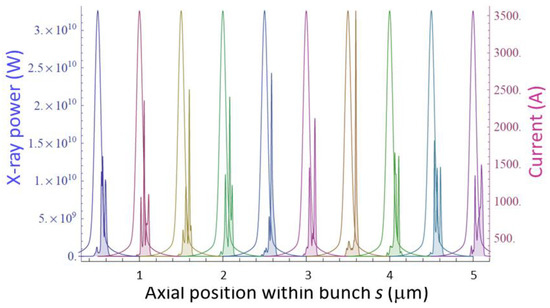
Figure 18.
For this case, using a 1 µm laser, the 0.3 A X-rays slip ahead of the electrons by 90 nm over 3000 undulator periods. A compression ratio of only 6 was used for this figure (compression from 600 A to 3.6 kA), which generated relatively wider microbunches than a compression ratio of 10 would, allowing, in turn, shorter laser wavelengths without violating the slippage constraint.
Two important limitations of the LABC approach that can degrade the X-ray flux are: (1) A relatively small fraction of the total bunch charge (about ) is contained within the microbunches for large microbunching compression factors ; (2) the instantaneous current drops off quickly and is only half the peak for the microbunch edges at the full bunch width. The first limitation can be addressed by using cascaded harmonic compression (adding beam energy modulation also at the second harmonic, shown in Figure 19). It is important to differentiate this form of cascaded compression (multiple laser modulation wavelengths and a single compressor) with that in [33] (single laser modulation wavelength but multiple compressors). Cascaded harmonic compression can increase the total charge contained in the microbunches to over 70% of the total bunch charge. The second limitation will impact the extracted power through reducing the Pierce gain parameter, Equation (1). Some recovery of the Pierce parameter can be made through increasing the microbunching compression ratio, but at the expense of decreased total charge within the microbunches.
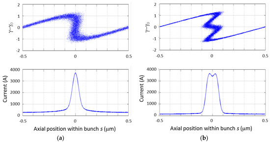
Figure 19.
(a) Bunching with a single frequency versus (b) harmonic bunching including the second harmonic. For this example (with a laser wavelength of 1 μm), the charge within the microbunch increases from 41% of the total charge in that period to 72% with the addition of the second harmonic modulation. These plots can be compared to the current profiles and longitudinal phase spaces shown in Figure 14b and Figure 15a,b.
Finally, we present an argument that the induced energy spread from CSR in a chicane compressor for creating a microbunched beam should be somewhat smaller than for a fully bunched beam. Ignoring coherent CSR effects between separate microbunches, we can estimate the induced energy spread from CSR in a compressor using [34]
where is the number of electron being compressed; and are the angle and the bending radius of the final dipole in the compressor, respectively; is the compressed axial length of the electrons; and is the classical radius of the electron, about . This is a reasonable approximation as the CSR fields are linear superpositions of the fields from each individual microbunch (as is the power radiated) and any coherent effects would be at wavelengths long compared to the microbunches and thus relatively small. Additionally, ELEGANT simulations of CSR from a collection of microbunches do not show coherent effects [35]. For comparing the induced energy spread from a single compressed bunch with that from a longer bunch with microbunches, we assume the number of electrons and the compressed length in a microbunch are both that of the full compressed bunch. Importantly, the needed for a microbunched beam is also about of that needed for compressing the full bunch, where D is the width of the dipoles in the compressor and S is the separation between the first, second, third, and fourth, and we are assuming the compressor angle is small. Combining these factors, we see that the induced energy spread scales as and, thus, the induced energy spread from CSR should be a bit smaller than if the entire bunch was compressed (e.g., by a factor of 2 for the example shown in Figure 12).
4.3. Application of Theory to a Point Design
Here, we provide specific design parameters for a MaRIE-class XFEL using LABC for the final compression stage. We know the required energy modulation amplitude from the plot shown in Figure 14a once we know the precompression energy spread. For that, we start with a distribution from a highly optimized C-band photoinjector based on the TOPGUN [19] geometry, shown in Figure 20.
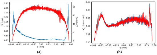
Figure 20.
(a) Current profile (red) and slice energy spread (blue) along a 100 pC bunch generated in a C-band TOPGUN photoinjector design [19,36]. (b) Slice emittance along the bunch.
Note the extremely low transverse emittance of this design. While this partially came at the sacrifice of peak current, the high TOPGUN gradient still was able to produce an initial peak current of about 20 A. This design needs a total compression of 150, which we achieve with a BC1 compression ratio of 15 and a LABC compression ratio of 10. In general, the extra energy modulation cost of the LABC compression leads to minimizing the compression in that section of the accelerator, relative to that in BC1. From Figure 14a, and , with 38.5% of the bunch charge captured within the microbunch FWHMs from Figure 16b. A series of GENESIS simulations indicate that a FWHM of at least 157 nm is needed to minimize slippage effects, which, in turn, requires a laser wavelength of at least 3.5 μm from Figure 16a.
Figure 20a indicates that the initial bunch slice energy spread is about 0.5 keV. MBI calculations through BC1 and up to the beam’s final energy, 12 GeV, before the LABC stage indicate that this intrinsic energy spread is too low and that a laser heater would still be required, see Figure 21. However, now the final energy spread is significantly smaller than from a conventional XFEL architecture, see Figure 8 for comparison. (There are two differences that lead to the smaller final energy spread between Figure 8 and Figure 21: First, for LABC, the final compression stage is at the full beam energy so there is no contribution from an L3 linac, which provided the largest contribution in Figure 8; and, second, the accelerator gradient is higher for this optimized solution than was used in the simulations leading to Figure 8). With a before-LABC rms energy spread of 32 keV and , the final, compressed energy spread is about 450 keV (about 0.004%), half of that shown in Figure 8, and now provides significantly more design headroom from Figure 4 (about a factor of 4). From , compressing the beam to generate the microbunches will require . Note that this is very small compared to the that would be needed to compress the full bunch at 12 GeV and that no dechirping is needed.
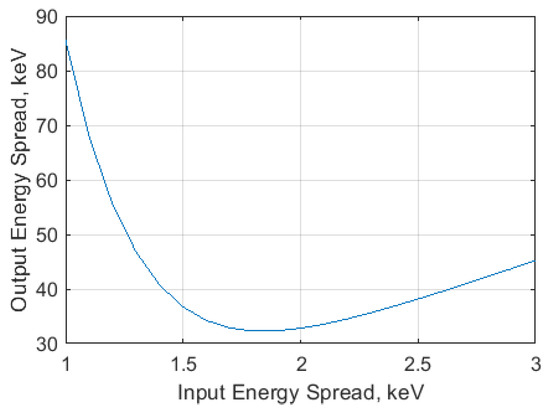
Figure 21.
RMS energy spread at the full accelerator energy before LABC versus laser-heater-induced energy spread for 120 MV/m accelerating gradient.
The combination of this low emittance and energy spread would more than double the X-ray fluence per bunch according to the curves in Figure 4. While we expect that the loss of electrons captured within the microbunches in a LABC architecture is roughly compensated by the gain of not losing electrons lasing due to the URWW in a conventional XFEL architecture, detailed GENESIS simulations including the non-Gaussian microbunch distributions are needed to determine the actual X-ray fluence.
5. Discussion
In this paper we have described a novel accelerator architecture which may lead to a significantly higher brightness electron beam for driving an XFEL. Specifically, this architecture, laser assisted bunch compression (LABC), may suppress beam degradation from the CSR, MBI, and URWW effects due to the lower average electron bunch current. We provided some background theory underlying LABC and analyzed the 10:1 compression contour in Figure 14 as a function of the normalized modulation amplitude A and normalized momentum compaction B. Importantly, LABC operates at a different position of A and B than eSASE, as the goal for LABC is to generate as flat a compressed current profile as possible. We compared these exact conditions for A and B to approximate values which can be used for performance estimates. We also considered more complex implementations, such as using cascaded compression including higher harmonic modulation. We evaluated LABC for a nominal MaRIE-class XFEL and showed the expected energy spread is reduced by about a factor of two, leading to significantly more design headroom and reduced operation risk. Detailed particle simulations now need to be optimized to verify these predicted improvements and to quantify how much improvement is possible. If these are promising, proof-of-principle demonstrations could be performed on existing XFELs.
Author Contributions
Conceptualization, B.E.C., P.M.A., C.W.B., Q.R.M., and N.Y.; formal analysis, P.M.A. and Q.R.M.; investigation, R.R.R.; writing—original draft, B.E.C., P.M.A., C.W.B., and Q.R.M.
Funding
P.M.A. gratefully acknowledges the support by the U.S. Department of Energy through the Los Alamos National Laboratory (LANL) LDRD Program.
Conflicts of Interest
The authors declare no conflict of interest.
References
- Juno—Mission to Jupiter. Available online: https://www.nasa.gov/mission_pages/juno/main/index.html (accessed on 22 September 2019).
- ITER—The Way to New Energy. Available online: https://www.iter.org/ (accessed on 22 September 2019).
- Wilson, L.A.; Rao, G.R. Frontiers of Materials Research, a Decadal Survey; National Academies Press: Washington, DC, USA, 2019. [Google Scholar]
- Dual Axis Radiographic Hydrodynamic Test Facility. Available online: https://www.lanl.gov/science-innovation/science-facilities/DARHT (accessed on 22 September 2019).
- Laser, Photonics, and Fusion Science: Science and Technology on a Mission. Available online: https://lasers.llnl.gov/ (accessed on 22 September 2019).
- Sheffield, R.L.; Barnes, C.W.; Tapia, J.P. Matter-radiation interactions in extremes (MaRIE) project overview. In Proceedings of the 38th International Free Electron Laser Conference, Santa Fe, NM, USA, 20–25 August 2017; pp. 24–28. [Google Scholar]
- Los Alamos Neutron Science Center. Available online: https://lansce.lanl.gov/ (accessed on 22 September 2019).
- National Nuclear Security Administration. Matter-Radiation Interactions in Extremes (MaRIE) Enterprise Requirements Validation Report. In Proceedings of the 38th International Free Electron Laser Conference, Santa Fe, NM, USA, 20–25 August 2017. [Google Scholar]
- Linac Coherent Light Source. Available online: https://lcls.slac.stanford.edu/ (accessed on 22 September 2019).
- Xie, M. Design optimization for an X-ray free electron laser driven by the SLAC linac. In Proceedings of the IEEE 1995 Particle Accelerator Conference, Dallas, TX, USA, 1–5 May 1995; IEEE Cat. No. 95CH35843. Volume 3, pp. 183–185. [Google Scholar]
- Russell, S.J.; Carlsten, B.E.; Duffy, L.D.; Krawczyk, F.L.; Lewellen, J.W., IV; Sheffield, R.L. MaRIE XFEL pre-conceptual reference design injector. In Los Alamos National Laboratory, Technical Report LA-UR-15-21963; Los Alamos National Laboratory: Los Alamos, NM, USA, 2010. [Google Scholar]
- Krasilnikov, M.; Stéphan, F.; Asova, G.; Grabosch, H.-J.; Gros, M.; Hakobyan, L.; Isaev, I.; Ivanisenko, Y.; Jachmann, L.; Khojoyan, M.; et al. Experimentally minimized beam emittance from anL-band photoinjector. Phys. Rev. Spéc. Top. Accel. Beams 2012, 15, 100701. [Google Scholar] [CrossRef]
- Lewellen, J.; Bishofberger, K.; Yampolsky, N.; Krawczyk, F.; Duffy, L.; Russell, S.; Sheffield, R.; Yampolsky, N. Status of the MaRIE X-FEL accelerator design. In Proceedings of the 6nd International Particle Accelerator Conference IPAC2015, Richmond, VA, USA, 3–8 May 2015; pp. 1894–1896. [Google Scholar]
- Saldin, E.L.; Schneidmiller, E.A.; Yurkov, M.V. Klystron instability of a relativistic electron beam in abunch compressor. Nucl. Instrum. Methods Phys. Res. A. 2002, 490, 1–8. [Google Scholar] [CrossRef]
- Lumpkin, A.H.; Thurman-Keup, R.; Edstrom, D.; Ruan, J.; Eddy, N.; Prieto, P.; Napoly, O.; Carlsten, B.E.; Bishofberger, K. Submacropulse electron-beam dynamics correlated with higher-order modes in Tesla-type superconducting rf cavities. Phys. Rev. Accel. Beams 2018, 21, 064401. [Google Scholar] [CrossRef]
- Carlsten, B.E. Tutorial on X-Ray Free-Electron Lasers. IEEE Trans. Plasma Sci. 2018, 46, 1900–1912. [Google Scholar] [CrossRef]
- Saldin, E.; Schneidmiller, E.; Yurkov, M. Calculation of energy diffusion in an electron beam due to quantum fluctuations of undulator radiation. Nucl. Instrum. Methods Phys. Res. Sect. A 1996, 381, 545–547. [Google Scholar] [CrossRef][Green Version]
- Cahill, A.D.; Rosenzweig, J.B.; Dolgashev, V.A.; Tantawi, S.G.; Weathersby, S. High gradient experiments with X-band cryogenic copper accelerating cavities. Phys. Rev. Accel. Beams 2018, 21, 102002. [Google Scholar] [CrossRef]
- Rosenzweig, J.; Cahill, A.; Carlsten, B.; Castorina, G.; Croia, M.; Emma, C.; Fukusawa, A.; Spataro, B.; Alesini, D.; Dolgashev, V.; et al. Ultra-high brightness electron beams from very-high field cryogenic radiofrequency photocathode sources. Nucl. Instrum. Methods Phys. Res. Sect. A 2018, 909, 224–228. [Google Scholar] [CrossRef]
- Carlsten, B.E.; Raubenheimer, T.O. Emittance growth of bunched beams in bends. Phys. Rev. E 1995, 51, 1453–1470. [Google Scholar] [CrossRef] [PubMed]
- Mitchell, C.E.; Ryne, R.D.; Yampolsky, N.A.; Qiang, J.; Carlsten, B.E. Large scale simulation of synchrotron radiation using a Lienard-Wiechert approach. In Proceedings of the 3rd International Particle Accelerator Conference IPAC2012, New Orleans, LA, USA, 2–25 May 2012; pp. 1689–1691. [Google Scholar]
- Bane, K.L.F.; Stupakov, G. Resistive wall wakefield in the LCLS undulator. In Proceedings of the 2005 Particle Accelerator Conference, Knoxville, TN, USA, 16–20 May 2005; pp. 3390–3392. [Google Scholar]
- Huang, Z.; Wu, J. Microbunching instability due to bunch compression. In SLAC National Accelerator Laboratory Technical Report SLAC-PUB-11597; SLAC National Accelerator Laboratory: Stanford, CA, USA, 2005. [Google Scholar]
- Borland, M.; Chae, Y.; Emma, P.; Lewellen, J.; Bharadwaj, V.; Fawley, W.; Krejcik, P.; Limborg, C.; Milton, S.; Nuhn, H.-D.; et al. Start-to-end simulation of self-amplified spontaneous emission free electron lasers from the gun through the undulator. Nucl. Instrum. Methods Phys. Res. Sect. A 2002, 483, 268–272. [Google Scholar] [CrossRef]
- Wu, J. (Undulator) wakefield measurements at LCLS. In Proceedings of the Compact X-ray FELs Using High-Brightness Beams, Berkeley, CA, USA, 5–6 August 2010. [Google Scholar]
- Huang, Z.; Brachmann, A.; Decker, F.-J.; Ding, Y.; Dowell, D.; Emma, P.; Frisch, J.; Gilevich, S.; Hays, G.; Hering, P.; et al. Measurements of the linac coherent light source laser heater and its impact on the x-ray free-electron laser performance. Phys. Rev. Spéc. Top. Accel. Beams 2010, 13, 020703. [Google Scholar] [CrossRef]
- Borland, M. Elegant: A flexible SDDS-compliant code for accelator simulation. In Argonne National Laboratory Technical Report Advanced Photon Source LS-287; Argonne National Laboratory: Lemont, IL, USA, 2000. [Google Scholar]
- Lewellen, J.W. (Los Alamos National Laboratory, Los Alamos, NM, USA). Private communication, 2019.
- Marksteiner, Q.R.; Anisimov, P.M.; Lewellen, J.W.; Yampolsky, N.A.; Carlsten, B. Using Laser Compression to Enhance Hard X-Ray FEL Performance; LA-UR-13-23470; Los Alamos National Laboratory: Los Alamos, NM, USA, 2013.
- Zholents, A.A. Method of an enhanced self-amplified spontaneous emission for x-ray free electron lasers. Phys. Rev. Spéc. Top. Accel. Beams 2005, 8, 040701. [Google Scholar] [CrossRef]
- Hemsing, E.; Stupakov, G.; Xiang, D.; Zholents, A. Beam by design: Laser manipulation of electrons in modern accelerators. Rev. Mod. Phys. 2014, 86, 897–941. [Google Scholar] [CrossRef]
- Reiche, S. GENESIS 1.3: A fully time-dependent FEL simulation code. Nucl. Instrum. Methods Phys. Res. A 1999, 429, 243–248. [Google Scholar] [CrossRef]
- Sudar, N.; Musumeci, P.; Gadjev, I.; Sakai, Y.; Fabbri, S.; Polyanskiy, M.; Pogorelsky, I.; Fedurin, M.; Swinson, C.; Kusche, K.; et al. Demonstration of Cascaded Modulator-Chicane Microbunching of a Relativistic Electron Beam. Phys. Rev. Lett. 2018, 120, 114802. [Google Scholar] [CrossRef] [PubMed]
- Derbenev, Y.S.; Rossbach, J.; Saldin, E.L.; Shiltsev, V.D. Microbunch radiative tail-head interaction. In DESY Technical Report TESLA-FEL 95-05; Deutsches Elektronben-Synchrotron: Hamburg, Germany, 1995. [Google Scholar]
- Robles, R. Bunch compression studies for a compact X-ray free electron laser. In Proceedings of the High Energy X-ray FELs Workshop, Santa Fe, NM, USA, 9–11 July 2019. [Google Scholar]
- Robles, R. (UCLA, Los Angeles, CA, USA). Private communication, 2019.
© 2019 by the authors. Licensee MDPI, Basel, Switzerland. This article is an open access article distributed under the terms and conditions of the Creative Commons Attribution (CC BY) license (http://creativecommons.org/licenses/by/4.0/).