Abstract
Magnetic fluid sealing is a novel sealing technology wherein magnetic fluids play a pivotal role in the sealing process. The yield stress of the magnetic fluid directly affectsits sealing performance and is governed by multiple interdependent factors. Conventional approaches that evaluate the effect of a single parameter while keeping other parameters constant are insufficient to fully characterize the relative contributions of each parameter to the yield stress. In this study, we investigate the preparation factors affecting the yield stress of kerosene-based magnetic fluids and propose a parameter sensitivity analysis method based on orthogonal experimental design to determine the optimal combination of factor levels within the studied range. The sensitivity of key preparation factors affecting the yield stress of kerosene-based magnetic fluids was determined via range and variance analyses of the orthogonal experimental data. The factors, ranked in descending order of sensitivity, were surfactant (C18H34O2) dosage, precipitant (NH3·H2O) dosage, and deionized water (H2O) volume. Moreover, the effects of different levels of the same factor were analyzed using multiple approaches. These findings provide a theoretical foundation for optimizing the preparation of magnetic fluids and enhancing their sealing performance.
1. Introduction
Magnetic fluids have numerous applications, with magnetic fluid sealing being one of the most technologically mature. These sealing systems have been widely implemented in military equipment, such as tank panoramic sight systems [1] and radar rotary joints [2], as well as in industrial equipment such as reaction vessels [3] and stirred tanks [4]. Figure 1 illustrates a typical magnetic fluid rotary seal configuration.
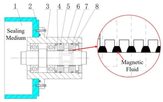
Figure 1.
Typical configuration of a magnetic fluid rotary seal. 1: Sealing chamber; 2, 5, 7: rubber O-rings; 3: housing; 4, 8: pole pieces; 6: permanent magnet.
In addition to traditional rubber and plastic seals, magnetic fluid (ferrofluid) rotary seals utilizing this novel functional material have become a major research focus worldwide. Magnetic fluids are intelligent nanofunctional materials whose properties can be controlled using magnetic fields. Magnetic fluids consist of stable colloidal suspensions of nanoscale magnetic particles (typically 3–15 nm in diameter) coated with surfactants and dispersed in carrier liquids. The surfactant molecules, featuring long-chain structures compatible with the carrier liquid, maintain a uniform and stable dispersion of the magnetic particles via steric hindrance effects. Organic solvents or water are typically used as carrier liquids. Owing to the combination of magnetic responsiveness and fluidity, magnetic fluids are extensively applied in sealing systems, sensors, dampers, and various other fields.
Magnetic fluids exhibit unique rheological properties owing to their responsiveness to external magnetic fields. Beyond conventional rheological factors such as shear rate and temperature, their rheological behavior can be controlled by applying external magnetic fields. Thus, the rheological properties of magnetic fluids can be modulated via deliberate design and control of the applied magnetic field.
Despite these advantages, magnetic fluid sealing faces critical challenges in practical applications. The yield stress of magnetic fluids directly affects the rotational resistance torque of the seal, ultimately influencing sealing performance and potentially leading to seal failure.
The yield stress characteristics significantly affect critical performance parameters, such as the starting torque of magnetic fluid seals. However, various highly coupled factors with complex interaction mechanisms influence the yield stress, and the underlying regulatory principles remain unclear. Therefore, a systematic investigation of the yield stress behavior of magnetic fluids and their regulatory mechanisms is necessary.
Current studies on the yield stress behavior of magnetic fluids predominantly employ chain-structure models to predict yield stress. When a magnetic fluid is subjected to zero-shear conditions, its viscosity stabilizes, resulting in negligible yield stress. The yield stress under different magnetic fields can be derived by fitting the flow curves of magnetic fluids using models such as the Herschel–Bulkley model. Zubarev et al. investigated the formation of droplet-like aggregates in magnetic fluids and their elongation/fragmentation under a combination of magnetic fields and shear flow, proposing a microscopic interpretation of the yield process [5]. Shahnazian et al. reported that magnetic fluids containing cobalt particles exhibit higher yield stress than those with Fe3O4 particles, with the yield stress magnitude strongly correlating with the large particle content, magnetic field strength, and testing gap [6].
Liu et al. investigated the microstructural evolution of magnetic fluids under steady shear and compression via molecular dynamics simulations [7]. They reported that magnetic particles initially form chain-like structures through dipole interactions under an applied magnetic field, and that both potential energy and static yield stress increase with magnetic field strength. Under steady shear, these one-dimensional chain/columnar structures transform into layered configurations. When compressed along the field direction, the yield stress increases because of the conversion of a major portion of compression work into repulsive potential energy [7]. López-López et al. compared the rheological properties of nanoparticle- and nanofiber-based magnetic fluids and proposed a theoretical model for the static yield stress [8]. Although their model qualitatively captures experimental trends, quantitative discrepancies remain.
Xinzhi et al. [9] investigated the influence of yield stress on the sealing performance of magnetic fluids and experimentally characterized the variation in breakaway torque and pressure resistance of magnetic fluid seals as a function of resting time. They derived modified theoretical formulae for pressure resistance and drag torque that explicitly account for yield stress effects. In a complementary study, Zhenkun [10] systematically examined the magnetoviscous properties, viscoelastic behavior, and yield stress/thixotropic characteristics of magnetic fluids and explored how magnetic fluid viscosity affects the sealing performance of liquid media.
Chen & Li [11] investigated the effect of particle size distribution on the resisting torque in magnetic fluid seals. Ferrofluid samples with varying particle size distributions were prepared by applying a magnetic field gradient, and their rheological properties were analyzed using a rheometer. The variation in the starting torque of magnetic fluid seals with particle size distribution was explained in terms of field-induced structure formation and destruction using magnetoviscous effect theory. Their results suggest a feasible approach to improve the performance of magnetic fluid seals. He et al. [12] experimentally investigated the starting torque of magnetic fluid seals and four key factors, namely the temperature, ferrofluid injection volume, standing time, and external pressure applied to the ferrofluid. They analyzed the variation in seal starting torque from the perspective of ferrofluid yield stress and discussed the influence of chain-like structures within the ferrofluid on yield stress from a microscopic viewpoint, including the formation mechanisms of these chain-like structures.
The yield stress of magnetic fluids depends on multiple interdependent factors. Conventional single-factor studies have investigated individual parameters while keeping others constant. However, such approaches cannot fully characterize the relative contributions of each parameter. We address this limitation by proposing a systematic research methodology based on an orthogonal experimental design to investigate the factors affecting the yield stress of magnetic fluids.
We performed a significance analysis of the various preparation parameters affecting the yield stress, conducted comparative evaluations of different levels of the same factor, and identified the key preparation parameters that significantly influence the yield stress. The major findings include the quantitative determination of the parameter significance hierarchy, identification of optimal level combinations for critical preparation variables, and establishment of process–property relationships. This study provides both theoretical and experimental foundations for improving the application prospects of kerosene-based ferrofluids in rotary magnetic fluid seals and reducing the influence of yield stress on starting torque.
2. Yield Stress of Magnetic Fluids
2.1. Mechanism of Yield Stress Generation in Magnetic Fluids
In the absence of an external magnetic field, the magnetic particles within magnetic fluids are randomly distributed due to Brownian motion, and the fluids exhibit Newtonian behavior. Under an external magnetic field, the magnetized dipoles interact strongly, leading to a reduction in Brownian motion and causing the magnetic particles to align along the field direction to form linear chain-like structures. These structures further evolve into more complex columnar or three-dimensional networks that increase the viscosity of the magnetic fluid owing to the magnetoviscous effect. Under such conditions, the magnetic fluid demonstrates non-Newtonian behavior. At high shear rates, the shear flow disrupts these chain structures, leading to a reduction in viscosity. The stress required to break these chain structures corresponds to the yield stress of the magnetic fluid. The factors influencing the yield stress of magnetic fluids include magnetic field intensity, particle volume fraction, particle size and shape, carrier liquid type, and additives.
As shown in Figure 2a, under an applied magnetic field, the magnetic particles within the static magnetic fluid aggregate to form chain-like or network structures. When pressure p is applied on one side of the magnetic fluid (Figure 2b), these chain/network structures deform and generate a resistance force directed against the pressure. This structural resistance, which prevents complete structural failure, represents the yield stress of the magnetic fluid. In rotational sealing applications (Figure 2c), at the critical point of shaft rotation initiation, the chain structures tilt owing to the relative displacement between the upper and lower surfaces of the magnetic fluid, producing a counteracting force opposing the shaft motion. Therefore, apart from overcoming the conventional sealing friction torque, the shaft must overcome the torque required to surpass the yield stress of the magnetic fluid. Macroscopically, this phenomenon manifests as an increase in the breakaway torque of magnetic fluid-sealing devices.
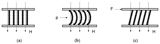
Figure 2.
Schematic of yield stress mechanisms. (a) Static state. (b) Pressurized state. (c) Rotational state.
Many types of magnetic fluids exhibit such yield stress behavior. When the applied shear stress exceeds a critical value, the magnetic fluid flows as a viscous liquid. Conversely, when the shear stress is below this threshold, the magnetic fluid exhibits solid-like characteristics and undergoes rigid-body motion.
The yield stress primarily originates from the formation of network structures. The number density of magnetic particles is on the order of n = 1017–1018 particles per cubic milliliter. Even if only 10% of the magnetic particles are involved in the formation of elongated chains and network structures, their total length becomes remarkably large. Assuming that the diameter of each magnetic particle is ( is the radius of each magnetic particle), the total length of the chains and networks can be expressed as
The total lateral surface area can be estimated as
In 1 mL of a magnetic fluid, the total linear length of the chain and network structures formed by the magnetic particles can reach an order of magnitude of 108 m. These elongated, particle-assembled chains bend and interlace, forming diverse structures of varying sizes and shapes that are densely distributed throughout the magnetic fluid. The combined effects of adhesive interactions at the carrier–liquid interface and intrinsic cohesive forces within the liquid collectively determine the flow characteristics of the magnetic fluid.
2.2. Calculation of Yield Stress in Magnetic Fluids
Consider a differential cubic control volume within a flowing magnetic fluid where multiple dipole chains (or network segments) penetrate all six surfaces. Focusing on the dxdy plane (Figure 3), we analyze a representative dipole chain under tensile deformation [13].
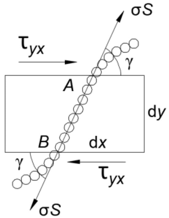
Figure 3.
Schematic of a dipole chain under tensile stress.
In Figure 4, the line segment AB represents one of the chains penetrating the differential plane dzdx. When the magnetic fluid approaches yielding, shear stress acts on the infinitesimal area dzdx. Given the negligible dimensions of the control volume, AB can be approximated as a straight line. Let denote the angle between AB and the reference plane . The stiffness of the carrier liquid under shear stress is negligible. According to the stress-partitioning principles based on relative stiffness, the entire shear stress generated by the incipient flow is borne exclusively by the magnetic particle chains. Therefore, the force balance equation is given by
where denotes the tensile stress acting on a single chain, is the cross-sectional area of the chain with = (ap is the radius of the magnetic particles), and denotes the number of chains penetrating the differential area dzdx and subjected to tensile stress.
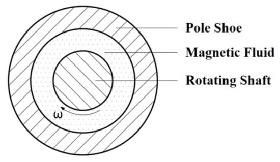
Figure 4.
Two-dimensional schematic of a magnetic liquid rotary seal.
Let denote the mathematical expectation (statistical mean) of , where follows a normal distribution:
or
The magnetic attraction between adjacent dipoles in a chain can be represented, to first approximation, by the diploe–dipole interaction force within a dipole pair and can be expressed as
where represents the magnetic force between dipoles. For linearly aligned dipole pairs, we obtain
If the dimensions and magnetic moments of all dipoles are identical, the strength condition can be derived as
Using the number of chains per unit area , the yield stress can be expressed as
Therefore, the yield stress of the magnetic fluid is given by
Within the microstructures penetrating the dzdx plane, a subset comprises linearly connected polar dipole chains. In the absence of an external magnetic field, these chains are randomly oriented. When an external field is applied, a fraction of the dipole chains align along the field direction, and the degree of alignment increases with the field strength. Under a vertical external magnetic field (along the y-axis, normal to the dzdx plane), a portion of the dipole chains penetrates the dzdx surface. The number of chains penetrating the surface increases with the intensity of the applied field, thereby increasing the areal chain density in the corresponding equation. Consequently, the yield stress of the magnetic fluid is positively correlated with the external field strength.
2.3. Influence of Yield Stress on the Rotational Resistance Torque of Seals
In magnetic fluid rotary seals, the rotation of the shaft must overcome the significant yield stress generated by the magnetic fluid, resulting in a sharp increase in torque—particularly the breakaway torque. This poses significant challenges in industrial applications, where it is essential to maintain the low viscosity and low yield stress activity of the magnetic fluid in seals after prolonged storage, and to ensure reliable startup and normal operation under varying working conditions.
Various theoretical models have been developed to analyze the rotational resistance torque in magnetic fluid seals. A simplified two-dimensional model was proposed, where the magnetic fluid is confined in the gap between the rotating shaft and pole piece [14].
Figure 4 shows a schematic of the cross-sectional structure of the magnetic fluid seal. This model [14] treats the magnetic fluid as a Newtonian fluid, and the viscous shear stress for a one-dimensional flow is calculated using the Navier–Stokes equation. The resisting torque can then be calculated as
where r1 denotes the radius of the rotating shaft, r2 is the inner diameter of the pole piece, is the angular velocity of the shaft, is the dynamic viscosity of the magnetic fluid, and l is the total axial length of the magnetic fluid in contact with the shaft.
Based on the increment in the pressure-bearing capacity of a single-stage magnetic fluid seal and considering only rotation in the absence of external pressure, the additional resisting torque of the single-stage magnetic fluid seal is given by
Therefore, the total resisting torque of the magnetic fluid seal is expressed as
where n denotes the number of sealing stages.
Thus, the yield stress of the magnetic fluid directly influences the rotational resistance torque in magnetic fluid rotary seals and determines the starting torque during seal startup.
2.4. Influence of Yield Stress on the Sealing Pressure-Bearing Capacity
In magnetic fluid seals, the yield stress of the magnetic fluid influences the sealing performance of the device. Inadequate sealing in certain regions can reduce the overall pressure resistance of the sealing system.
The yield stress of the magnetic fluid strongly affects the pressure resistance of the magnetic fluid seals. Let r be the radius of the magnetic fluid seal, Lt the width of the pole teeth, and Lg the sealing gap with Lg ≪ r. At the critical state when magnetic particle chains begin to rupture, the equilibrium condition yields
Thus,
Because the constitutive equations for magnetic fluids cannot be derived theoretically, the results of theoretical analyses remain qualitative. Therefore, the yield stress of magnetic fluids must be experimentally determined. During rheometer measurements, an external magnetic field is applied for characterizing magnetic fluids, and the yield stress is measured as the value of the shear stress at zero shear rate. In magnetic fluid sealing applications, the yield stress can also be calculated by measuring the breakaway torque of the seal.
3. Experimental Methods
3.1. Preparation of Magnetic Fluids
Methods for preparing magnetic fluids include mechanical grinding [15,16,17], chemical co-precipitation [18], anion exchange resin processing [19], hydrogen reduction [20], spark erosion [21], ultraviolet decomposition [20], thermal decomposition [22,23], vacuum evaporation [24], and electrodeposition [25]. Among these, chemical co-precipitation [26] has been widely adopted owing to its strong controllability, high efficiency, and excellent operational feasibility. This method was employed for synthesizing the kerosene-based magnetic fluid in the present study. The experimental procedure for chemical co-precipitation is as follows (Figure 5):
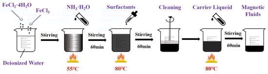
Figure 5.
Preparation path of kerosene-based magnetic fluid.
- (1)
- Specified quantities of FeCl3·6H2O and FeCl2·4H2O were weighed and dissolved in deionized water to obtain an iron salt solution.
- (2)
- The iron salt solution was heated and stirred in a water bath. Ammonium hydroxide (NH3·H2O), serving as the precipitating agent, was then added, and stirring was continued.
- (3)
- Oleic acid (C18H34O2) was added as the surfactant, and the mixture was subsequently stirred to obtain a suspension.
- (4)
- The suspension was placed on a permanent magnet for magnetic separation. It was washed with deionized water until the supernatant pH reached 7, yielding nanosized magnetic particles.
- (5)
- Kerosene was used as the carrier liquid. The carrier liquid and an appropriate amount of deionized water were added to the magnetic particles. The mixture was heated in an 80 °C water bath under continuous stirring for 60 min.
- (6)
- The residual deionized water was removed from the product to obtain the kerosene-based magnetic fluid.
A stable kerosene-based magnetic fluid was obtained using the above-described procedure. The sources and specifications of the main reagents used are listed in Table 1. The carrier liquid, kerosene, was sourced from Macklin. The primary instruments used for magnetic fluid preparation are listed in Table 2.

Table 1.
Sources and specifications of the main reagents.
Table 2.
Experimental instruments.
3.2. Principles and Design of an Orthogonal Experimental Method
Orthogonal experimental design is a scientific methodology that employs orthogonal arrays to systematically investigate the influence of multiple factors on experimental outcomes. An appropriate orthogonal array is selected according to the specific requirements of the practical problems, serving both as the experimental framework and statistical basis.
The standard notation for an orthogonal array is denoted as LN(mk), where L denotes the orthogonal table encompassing various experimental combinations, N is the total number of experimental trials, m is the number of levels for each factor, and k denotes the maximum number of factors that can be accommodated in the experiment.
During the preparation of magnetic fluids, several factors influence the resulting yield stress. For kerosene-based magnetic fluids, the quantities of the precipitating agent (NH3·H2O), deionized water (H2O), and surfactant (C18H34O2) were identified as three critical process parameters. Accordingly, the dosages of the precipitant and surfactant, along with the volume of deionized water, were chosen as three variable parameters for an orthogonal experimental investigation of the yield stress of kerosene-based magnetic fluids. The amounts of other preparation materials employed are listed in Table 3.
Table 3.
Dosage of preparation materials.
If each parameter were to have three levels, a full factorial experiment would require 33 = 27 preparation trials, requiring substantial human and material resources. In contrast, the orthogonal experimental design enables efficient investigation of multiple factors and levels by selecting representative test points based on orthogonality. These points exhibit “uniform dispersion and comparable regularity,” making the method a highly effective, rapid, and economical alternative. The results of each group were evaluated after configuring the factor levels using an orthogonal array. Since the yield stress of magnetic fluids can be directly measured using a rheometer, it was adopted as the evaluation metric.
Based on prior experience with the preparation of kerosene-based magnetic fluids, the following factor levels were chosen: precipitant dosage: 120 and 140 mL (two levels); deionized water volume: 400, 500, and 600 mL (three levels); and surfactant dosage: 7, 10, and 12 mL (three levels). The primary levels were selected based on common preparation conditions. The factor-level distribution is presented in Table 4. To accommodate the factors with different numbers of levels, the pseudo-level method was applied. This conventional engineering technique reconciles the mixed-level conditions within the framework of a standard L9 orthogonal array, thus maintaining the required orthogonality in the experimental design. Using the orthogonal experimental design, only nine test groups were required, and these are listed in Table 5. Therefore, the number of experiments was significantly reduced while retaining statistical validity.
Table 4.
Factor levels for orthogonal experimental design.
Table 5.
Orthogonal experimental design array.
Range analysis [27] and analysis of variance (ANOVA) [28,29] were conducted to process the orthogonal experimental data and analyze the relative significance of different parameters on the experimental results [30,31].
3.3. Measurement of the Yield Stress of Magnetic Fluids
The yield stress values of the prepared kerosene-based magnetic fluid were measured using an Anton Paar MCR 301/302 rotational rheometer at the Tribology Key Laboratory of Tsinghua University, as shown in Figure 6. The magnetic field was generated using the MRD 170 accessory unit of the rheometer, which employs an electromagnetic coil installed beneath the measuring plate. The centers of the coil and plate were precisely aligned, ensuring a uniform magnetic field across the measurement region, oriented perpendicular to the velocity gradient of the sample. A current range of 0–5 A produced a magnetic field strength of 0–1 T, which was calibrated prior to the experiments. The temperature was controlled using a VT2 liquid-circulation thermostat system equipped with a rheometer. The technical specifications of the rheometer are listed in Table 6. The MCR 301/302 rheometer employs an air-bearing system that enables both rotational and oscillatory measurements. A parallel-plate fixture with rotational measurement methodology was used to determine the yield stress of the magnetic fluid at laboratory temperature (25 °C).
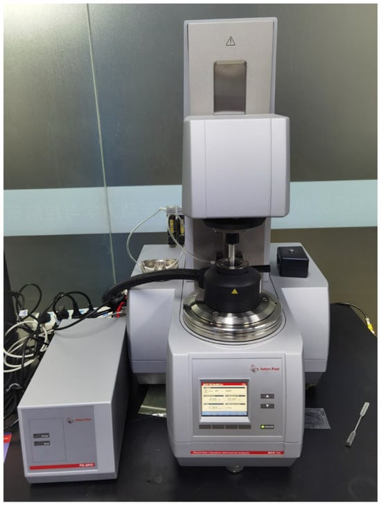
Figure 6.
Photograph of the Anton Paar MCR 301/302 rotational rheometer.
Table 6.
Technical specifications of the Anton Paar MCR 301/302 rheometer.
The flow curve of a magnetic fluid, which depicts the relationship between shear stress (y-axis) and shear rate (x-axis), can be obtained using a rheometer. In the absence of an external magnetic field, the shear stress is proportional to the shear rate, and there is essentially no intercept on the y-axis. Under these conditions, the magnetic fluid exhibits nearly Newtonian behavior, indicating the absence of yield stress. Under an external magnetic field, the shear stress increases with the shear rate, but the rate of increase gradually diminishes. Moreover, the flow curve shows a finite intercept on the y-axis, demonstrating the non-Newtonian characteristics of the magnetic fluid. The yield stress is measured during the initial phase of measurement when the shear rate approaches zero.
4. Results
4.1. Fundamental Properties of the As-Prepared Magnetic Fluids
Based on the orthogonal experimental design, nine types of kerosene-based magnetic fluids were synthesized via chemical co-precipitation. The fundamental properties of these magnetic fluids were characterized in terms of magnetic particle dispersibility, stability, and magnetization performance.
4.1.1. Dispersibility of Magnetic Particles
The nine prepared kerosene-based magnetic fluid samples were observed using a Hitachi HT7700 transmission electron microscope (TEM, Hitachi, Japan), and the results are shown in Figure 7. The synthesized magnetic particles exhibited a predominantly spherical morphology with an average particle size of approximately 10 nm, indicating generally favorable dispersibility. A small fraction of particles showed slight agglomeration. However, as the TEM images were obtained under non-magnetic conditions, the differences in magnetic particle aggregation and chain-like alignment among the nine magnetic fluids are not distinctly demonstrated.
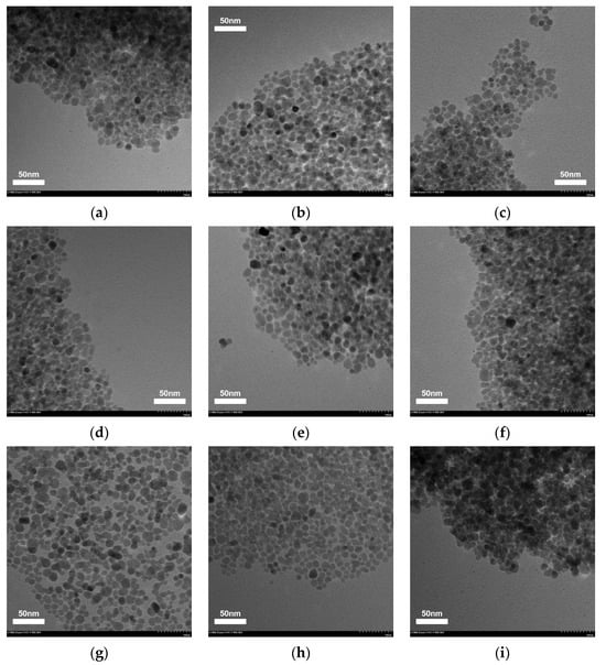
Figure 7.
TEM images of the nine types of kerosene-based magnetic fluids. (a) Sample 1. (b) Sample 2. (c) Sample 3. (d) Sample 4. (e) Sample 5. (f) Sample 6. (g) Sample 7. (h) Sample 8. (i) Sample 9.
Statistical analysis of particle size for all samples was performed using Nano Measure software 1.2. The resulting particle size distributions are presented in Table 7 and Figure 8. The statistical results indicate that the particle size distributions of all samples conform to a normal distribution.
Table 7.
Statistical results of particle size.
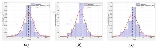
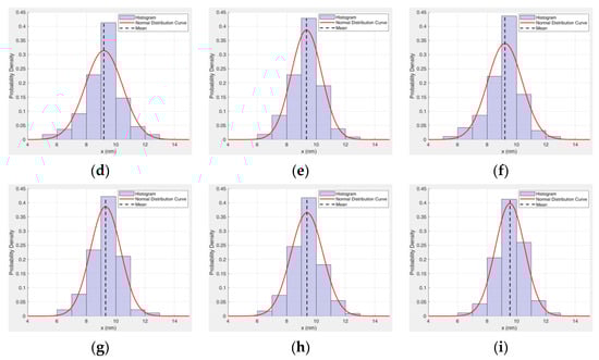
Figure 8.
Statistical graph of magnetic particle size. (a) Sample 1. (b) Sample 2. (c) Sample 3. (d) Sample 4. (e) Sample 5. (f) Sample 6. (g) Sample 7. (h) Sample 8. (i) Sample 9.
4.1.2. Stability
Under an applied magnetic field, magnetic particles form chain-like structures, resulting in the development of yield stress in the magnetic fluid. However, upon removal of the magnetic field, the particles undergo complete demagnetization and remain uniformly suspended within the carrier liquid. Visual inspection confirmed the absence of particle sedimentation in the magnetic fluid under such conditions. This is consistent with the relationship given in the following formula [32]:
where C is a constant, k0 is the Boltzmann constant, T denotes the temperature, is the density of the magnetic particles, is the density of the magnetic fluids, g is the acceleration due to gravity, h is the height of the magnetic particle from the reference point, and is the volume of a single magnetic particle.
The critical size of magnetic particles is given by
When the magnetic particle sizes are smaller than the critical dimension, a stable suspension can be formed under the influence of a gravitational field.
The stability analysis of the nine kerosene-based magnetic fluids was conducted via direct observation. Appropriate amounts of each magnetic fluid were placed in test tubes and allowed to stand for 0, 10, 30, 60, and 90 days. Freshly prepared magnetic fluid (0-day standing time) served as the reference. A comparative analysis of the magnetic fluids after different standing periods with the 0-day reference revealed no evidence of phase separation, particle agglomeration, or sedimentation in any of the nine samples. The macroscopic appearance of the magnetic fluid after being allowed to stand for 90 days under an identical applied magnetic field is shown in Figure 9. Furthermore, the saturation magnetization remained unchanged over the 90-day period. It was therefore concluded that all nine prepared kerosene-based magnetic fluids exhibit excellent stability.
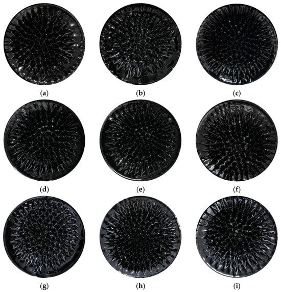
Figure 9.
Macroscopic images of the nine magnetic fluid samples under an identical applied magnetic field. (a) Sample 1. (b) Sample 2. (c) Sample 3. (d) Sample 4. (e) Sample 5. (f) Sample 6. (g) Sample 7. (h) Sample 8. (i) Sample 9.
4.1.3. Magnetization Properties
Under an applied magnetic field, magnetic particles within magnetic fluids assemble into chain-like or columnar microstructures. The yield stress of the fluid primarily arises from the resistance of these structures to shear deformation. This yield stress is governed by several key factors, including magnetic particle morphology, particle volume fraction, and saturation magnetization.
In this study, the kerosene-based magnetic fluids with spherical magnetic particles of relatively uniform size and distribution was used; therefore, the influence of particle morphology on the results is considered negligible. Volume fraction plays a critical role: within an appropriate range, yield stress increases with increasing particle concentration. At low volume fractions, chains are sparse and mechanically weak, leading to low yield stress. As the concentration rises, more particles contribute to microstructure formation, enhancing the yield stress. However, at excessively high volume fractions, particle aggregation occurs, colloidal stability deteriorates, and dense packing hinders the formation of well-aligned field-induced structures. This results in a diminished increase in yield stress, accompanied by a sharp rise in viscosity and loss of fluidity.
Saturation magnetization governs the magnetic dipole interactions between particles. Generally, higher saturation magnetization significantly enhances the yield stress. Since saturation magnetization is approximately linearly proportional to the magnetic particle volume fraction, it can be used as an indicator to assess the effect of concentration on yield stress. It should be noted, however, that the overall magnetorheological response is also co-determined by other factors such as the magnetization curve profile, particle size distribution, and colloidal stability.
The saturation magnetization of the magnetic fluids was characterized using a Model EZ8 vibrating sample magnetometer (MicroSense, Lowell, MA, USA) at 25 °C. The results are summarized in Table 8, and the magnetization curves are presented in Figure 10. The results indicate that all nine samples exhibit superparamagnetic behavior under magnetic fields, with no remanent magnetization nor coercivity.
Table 8.
Vibrating sample magnetometer measurements for different magnetic fluids.
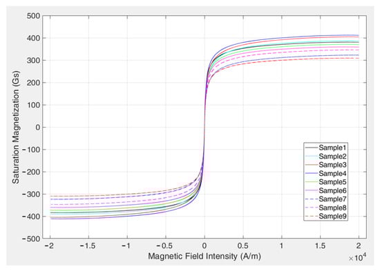
Figure 10.
Magnetization curves of the magnetic fluid samples.
4.2. Orthogonal Test Results
The applied currents were 0, 0.5, 1, and 2 A, corresponding to magnetic field intensities of 0, 19, 36, and 65 kA/m, respectively. The yield stress of each magnetic fluid was measured under different magnetic field intensities. Three measurements were performed for each sample, and the resulting data exhibited a standard error of 2–5%. The average values of the experimental measurements are summarized in Table 9. The relationship between yield stress and magnetic field strength for the kerosene-based magnetic fluid, with error bars indicative of standard error, is illustrated in Figure 11.
Table 9.
Yield stress measurements of different kerosene-based magnetic fluids.
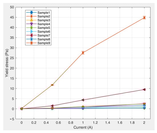
Figure 11.
Dependence of yield stress on magnetic field strength for various kerosene-based magnetic fluids.
5. Sensitivity Analysis of Magnetic Fluid Preparation Parameters
5.1. Sensitivity Analysis of Preparation Parameters Based on Range Analysis
The range analysis method employs mathematical statistics to calculate the range value for each column in an orthogonal array. By analyzing the mean values and the corresponding ranges of each factor, the optimal level combination and relative significance of the influencing parameters can be determined. The range of a factor is defined as the difference between its maximum and minimum mean values across all levels. A larger range indicates a more significant influence, and thus a primary order of importance, whereas a smaller range suggests a weaker influence and classifies the factor as secondary.
The first step in range analysis involves calculating the total value for each specific level j of a given factor i. This value is obtained by summing all experimental results corresponding to the j-th level of the i-th factor. Subsequently, the level mean is computed using the formula
where n denotes the number of occurrences of level j.
The range value for each factor can then be calculated as
The value range for each factor was determined using the above equations. The range analysis was performed using the measured yield stress values of the kerosene-based magnetic fluids (Table 9) to evaluate the preparation parameters. The calculation results are listed in Table 10.
Table 10.
Range analysis of factors influencing the yield stress of kerosene-based magnetic fluids.
The results indicate that under an applied magnetic field, the preparation parameters of the kerosene-based magnetic fluids exhibited the following descending order of influence on the yield stress based on their range values: surfactant dosage > deionized water volume > precipitant dosage. This quantitative ranking suggests that the surfactant dosage (largest range value) is the most dominant factor governing the yield stress behavior, the deionized water volume exerts a secondary but measurable influence, and the precipitant dosage (smallest range value) exerts the least significant effect.
Figure 12 shows the variation in the range values (R) for the different factors with increasing current (magnetic field strength). The results indicate that the range values for all the factors positively correlate with the magnetic field intensity. This proportional relationship leads to more pronounced parameter effects under strong magnetic fields. Surfactant dosage remained the dominant factor and was particularly significant at higher field strengths. These trends confirm that an increase in the magnetic field strength increases the sensitivity of the yield stress to preparation parameters, especially the surfactant concentration.
Figure 12.
Comparison of range values of the factors affecting yield stress for kerosene-based magnetic fluids under different magnetic fields.
Figure 13 shows the variation trends of yield stress with different factor levels. Under the combined influence of multiple factor levels, the deionized water content exhibited an initial positive and subsequent negative correlation with the yield stress. Specifically, as the deionized water content increased, the degree of its influence on the yield stress first increased and then decreased. In contrast, both the precipitant and surfactant dosages exhibited an overall negative correlation with the yield stress of the kerosene-based magnetic fluids. With increasing dosages of these components, their influence on the yield stress decreased significantly.
Figure 13.
Variation in the yield stress of kerosene-based magnetic fluids with different factor levels. (a) Precipitant. (b) Deionized water. (c) Surfactant.
5.2. Sensitivity Analysis of Preparation Parameters Based on Variance Analysis
Although range analysis can identify the relative magnitude of influence of each factor on the yield stress, it cannot assess the statistical significance of these effects or quantify the degree of significance. In contrast, ANOVA can be used to eliminate the effect of experimental errors, evaluate the effects of factor-level variations, and determine the sensitivity of different influencing factors. Thus, ANOVA enables a rigorous investigation into the statistical significance of the effects of these factors on the yield stress of kerosene-based magnetic fluids.
Accordingly, ANOVA was applied to the preparation parameter data to examine the significance of the three key factors—the precipitant dosage, deionized water volume, and surfactant dosage—on the yield stress. The parameters can be systematically adjusted based on the results to achieve targeted control over the rheological properties of the magnetic fluid.
The total value for each factor level was first calculated. Subsequently, the sum of squares and the corresponding degrees of freedom were computed as follows:
where denotes the number of horizontal replicates, and denotes the sum of the orthogonal experimental measurement data.
Next, the error sum of squares , defined as the sum of squares from the blank columns and several relatively small column sums of squares, was determined. The corresponding degrees of freedom were obtained as the sum of the degrees of freedom of these columns. In the absence of repeated trials and blank columns, the column with the smallest sums of squares may be selected to represent the error sum of squares.
The results are summarized in Table 11, where the mean square and F-ratio are computed. Here, .
Table 11.
Analysis of variance (ANOVA) results.
The rejection region corresponding to a given significance level α was determined, and a parameter sensitivity analysis was conducted. Generally, when F-ratio < F0.05 (5% confidence level), the factor is considered to have no significant effect on the evaluation index. When F0.05 < F-ratio < F0.01 (1% confidence level), the factor is considered as a sensitive parameter with a significant influence on the evaluation index. When F-ratio > F0.01 (1% confidence level), the factor is identified as a highly sensitive parameter that has a significant effect on the evaluation index [21]. The ANOVA results obtained from the orthogonal experimental data are presented in Table 12.
Table 12.
ANOVA for factors influencing the yield stress of kerosene-based magnetic fluids.
The F-distribution table indicates that F0.05 (2,6) = 19.33 and F0.01 (2,6) = 99.33. An analysis of the data shown in Table 10 indicated that, for magnetic flux densities at 0 and 0.5 A, all three factors yield F-ratios below 19.33, suggesting no significant effect on the yield stress. At 1 A, the F-ratio for the surfactant dosage lies between 19.33 and 99.33, suggesting a significant influence on the yield stress, thereby identifying it as a sensitive parameter. For a higher magnetic flux density at 2 A, the F-ratio for the surfactant dosage exceeds 99.33, indicating a highly significant effect, identifying it as an extremely sensitive parameter. Moreover, the significance of the surfactant dosage increases rapidly with increasing magnetic field strength.
Based on the magnitude of the F-ratios, the sensitivity of the parameters affecting the yield stress of the kerosene-based magnetic fluids follows the order surfactant dosage > precipitant dosage > deionized water content.
Therefore, these results are consistent with those of range analysis.
Theoretical analysis revealed that the yield stress of magnetic fluids can be determined based on the number of chains per unit area, interparticle interactions, and the size distribution of magnetic particles. Based on the experimental results, when no external magnetic field is applied or when the magnetic field strength is relatively low, the three preparation factors exhibit comparable levels of influence on the yield stress of the kerosene-based magnetic fluid. However, as the magnetic field strength increases, their impacts diverge: the surfactant demonstrates the most pronounced effect on the yield stress, followed by the precipitating agent, while the influence of deionized water remains relatively minor.
During magnetic fluid preparation, deionized water helps maintain product purity primarily by controlling the ionic strength within the system. This modulates the electrostatic interactions between particles, thereby influencing the yield stress of the magnetic fluid. Nevertheless, deionized water content exerts a relatively minor influence on the yield stress.
In this study, ammonium hydroxide (NH3·H2O) was used as the precipitating agent for the chemical reaction. The OH− ions it provides promote the coprecipitation of metal salt solutions to form ultrafine magnetic particles, exerting a decisive influence on their size, morphology, and size distribution. Larger magnetic particles exhibit stronger magnetic attraction, facilitating the formation of robust chain-like structures, which leads to an increase in yield stress. Conversely, the uniformity of narrow particle size distributions enables the formation of highly ordered chain-like structures under a magnetic field. In such cases, the interparticle forces are more consistent, generally resulting in a higher yield stress under magnetic fields. Therefore, the precipitating agent exerts a more substantial influence on the yield stress of magnetic fluids.
Surfactants serve primarily as dispersing agents during the preparation of magnetic fluids, preventing particle agglomeration and playing a critical role in maintaining the stability of magnetic fluids in practical applications. The steric hindrance effect provided by the surfactant enables uniform and stable dispersion of magnetic particles within the carrier liquid, attenuates the van der Waals forces between particles, and suppresses magnetic dipole interactions. When the surfactant quantity is sufficient to form a complete, dense, and stable coating on the particles, each particle is effectively isolated by surfactant molecules, resulting in the lowest yield stress. If the surfactant amount is insufficient, incomplete particle coating occurs, which leads to agglomeration and the formation of robust chain-like or columnar network structures, which significantly increase the yield stress. Conversely, if an excessive amount of surfactant is used, the surplus surfactant molecules disperse within the magnetic fluid in the form of micelles or free molecules, increasing the viscosity of the magnetic fluid and consequently raising the yield stress. Therefore, the amount of surfactant exserts a more pronounced influence on the yield stress of magnetic fluids.
6. Conclusions
This study investigated the yield stress of kerosene-based magnetic fluids using a combination of theoretical and experimental approaches. The main conclusions are as follows:
- (1)
- The influence of yield stress on the starting torque of rotary seals using kerosene-based magnetic fluids was examined. Theoretical calculations showed that the yield stress affects both the starting torque and pressure resistance of magnetic fluid seals. These results provide a theoretical basis for optimizing the preparation of magnetic fluids and enhancing their sealing performance.
- (2)
- Using yield stress as the evaluation index, an orthogonal experimental design was introduced to assess parameter sensitivity. Compared with 27 preparation tests, the orthogonal experimental method required only nine sets of preparation parameters to determine the sensitivity of the preparation parameters affecting the yield stress. This approach effectively identified the key factors and optimal combination of factor levels within the studied range while reducing the number of experiments required.
- (3)
- Range and variance analyses of the orthogonal experimental data revealed that different preparation factors exhibit varying degrees of influence on the yield stress. Under low magnetic field intensities, all three factors show non-significant effects. As the magnetic field intensity increases, the significance of the surfactant dosage becomes markedly enhanced. The overall sensitivity order of the factors is surfactant dosage > precipitant dosage > deionized water volume. These findings provide a theoretical foundation for optimizing the preparation of magnetic fluids and enhancing their sealing performance.
Overall, the results obtained in this study provide both theoretical and experimental foundations for improving the application prospects of kerosene-based magnetic fluids in rotary seals and mitigating the impact of their yield stress on the starting torque.
Author Contributions
Conceptualization, M.Z.; methodology, M.Z. and L.J.; software, M.Z.; validation, M.Z. and L.J.; formal analysis, M.Z.; investigation, M.Z.; resources, M.Z.; data curation, M.Z.; writing—original draft preparation, M.Z.; writing—review and editing, M.Z.; visualization, M.Z.; supervision, Y.F.; project administration, Y.F.; funding acquisition, Y.F. All authors have read and agreed to the published version of the manuscript.
Funding
This research was funded by the 2024 Langfang City Science and Technology Research and Development Program (Self-funded Projects), grant number 2024011077, and Fundamental Research Funds for the Central Universities, grant number 3142024034.
Institutional Review Board Statement
Not applicable.
Informed Consent Statement
Not applicable.
Data Availability Statement
The original contributions presented in this study are included in the article. Further inquiries can be directed to the corresponding author(s).
Conflicts of Interest
Yu Feng is employed by “China Coal Technology & Engineering Group Co., Ltd.”. The remaining authors declare that the research was conducted in the absence of any commercial or financial relationships that could be construed as a potential conflict of interest.
References
- Chen, Y.; Li, D. Design and experiments for magnetic fluid seal of tank panoramic mirror. Acta Armamentarii 2011, 32, 1428–1432. [Google Scholar]
- Fan, D. The Study of Magnetoviscous Effects in High and Low Temperature. Master’s Thesis, Beijing Jiaotong University, Beijing, China, 2012. [Google Scholar]
- Cheng, H. The Research of Magnetic Fluid Sealing on Reaction Kettle. Master’s Thesis, Beijing Jiaotong University, Beijing, China, 2016. [Google Scholar]
- Liu, H.; Yan, Z.; Xu, D. Transformation of acrylic acid polymerization production line in magnetic liquid seal. Mod. Chem. Res. 2019, 10, 156–158. [Google Scholar]
- Zubarev, A.Y.; Iskakova, L.Y. Rheological properties of ferrofluid with drop-like aggregates. Phys. A 2007, 376, 38–50. [Google Scholar] [CrossRef]
- Shahnazian, H.; Odenbach, S. Rheological investigations of ferrofluids with a shear stress controlled rheometer. J. Phys. Condens. Matter 2008, 20, 204137. [Google Scholar] [CrossRef]
- Liu, T.; Gu, R.; Gong, X.; Xuan, S.; Wu, H.; Zhang, Z. Structural and rheological study of magnetic fluids using molecular dynamics. Magnetohydrodynamics 2010, 46, 257–270. [Google Scholar] [CrossRef]
- López-López, M.T.; Gómez-Ramírez, A.; Rodríguez-Arco, L.; Durán, J.D.G.; Iskakova, L.; Zubarev, A. Colloids on the frontier of ferrofluids. Rheological properties. Langmuir 2012, 28, 6232–6245. [Google Scholar] [CrossRef]
- He, X.; Li, D.; Hao, R. The influence of magnetic fluid yield stress on the performance of magnetic fluid seal. Acta Armamentarii 2015, 36, 175–181. [Google Scholar]
- Li, Z. Study on the Rheological Property of Magnetic Liquids and Its Influence on Sealing Fluids Performance. Ph.D. Thesis, Beijing Jiaotong University, Beijing, China, 2019. [Google Scholar]
- Chen, S.; Li, D. Influence of particle size distribution of magnetic fluid on the resistance torque of magnetic fluid seal. J. Magn. 2017, 22, 605–609. [Google Scholar] [CrossRef]
- He, X.; Wang, Z.; Li, D. Influence of yield stress on the starting torque of magnetic fluid seal. Acta Armamentarii 2022, 43, 892–898. [Google Scholar]
- Chi, C. The Foundation of Physics and Application of Magnetic Fluid; Beihang University Press: Beijing, China, 2011. [Google Scholar]
- Yanhong, C.; Decai, L.; Rongkun, D. Experimental analysis of starting torque of perfluoropolyethers-based magnetic fluid seal. J. Harbin Eng. Univ. 2017, 38, 1316–1321. [Google Scholar]
- Stephen, P.S. Low Viscosity Magnetic Fluid Obtained by the Colloidal Suspension of Magnetic Particles. U.S. Patent US3215572A, 2 November 1965. [Google Scholar]
- Pei, S. Preparation and Characterization of Silicon Oil Based Ferrofluid. Master’s Thesis, Beijing Jiaotong University, Beijing, China, 2014. [Google Scholar]
- Jin, H. The Preparation of Machine Oil-Based Magnetic Liquid and Thermal Magnetic Studies. Master’s Thesis, Shenyang University of Technology, Shenyang, China, 2015. [Google Scholar]
- Reimers, G.; Khalafalla, S. Production of Magnetic Fluid by Peptization Techniques. U.S. Patent US3843540A, 22 October 1974. [Google Scholar]
- Jackson, W.M.; Hengeveld, F.W. Sols of Gamma Ferric Oxide and Their Preparation. U.S. Patent US3480555A, 25 November 1969. [Google Scholar]
- Hoon, S.R.; Kilner, M.; Russell, G.J.; Tanner, B.K. Preparation and properties of nickel ferrofluids. J. Magn. Magn. Mater. 1983, 39, 107–110. [Google Scholar] [CrossRef]
- Berkowitz, A.E.; Walter, J.L. Ferrofluids prepared by spark erosion. J. Magn. Magn. Mater. 1983, 39, 75–78. [Google Scholar] [CrossRef]
- Kilner, M.; Hoon, S.; Lambrick, D.; Potton, J.; Tanner, B. Preparation and properties of metallic iron ferrofluids. IEEE Trans. Magn. 1984, 20, 1735–1737. [Google Scholar] [CrossRef]
- Thomas, J.R. Preparation and magnetic properties of colloidal cobalt particles. J. Appl. Phys. 1966, 37, 2914–2915. [Google Scholar] [CrossRef]
- Kimoto, K.; Kamiya, Y.; Nonoyama, M.; Uyeda, R. An electron microscope study on fine metal particles prepared by evaporation in argon gas at low pressure. Jpn. J. Appl. Phys. 1963, 2, 702–713. [Google Scholar] [CrossRef]
- Luborsky, F.E.; Opie, J.D. Adsorption of metals on iron particles in mercury. J. Appl. Phys. 1963, 34, 1317–1318. [Google Scholar] [CrossRef]
- Socoliuc, V.; Avdeev, M.V.; Kuncser, V.; Turcu, R.; Tombácz, E.; Vékás, L. Ferrofluids and bio-ferrofluids: Looking back and stepping forward. Nanoscale 2022, 14, 4786–4886. [Google Scholar] [CrossRef]
- Field, G.J.; Nau, B.S. Film thickness and friction measurements during reciprocation of a rectangular section rubber seal ring. In Proceedings of the 6th International Conference on Fluid Sealing, Munich, Germany, 27 February–2 March 1973; pp. 45–56. [Google Scholar]
- Field, G.J.; Nau, B.S. The effects of design parameters on the lubrication of reciprocating rubber seals. In Proceedings of the 7th International Conference on Fluid Sealing, Nottingham, UK, September 1975; pp. 1–13. [Google Scholar]
- Kaneta, M.; Todoroki, H.; Nishikawa, H. Experimental investigation of friction and sealing characteristics of flexible seals for reciprocating motion. In Proceedings of the 5th International Conference on Fluid Sealing, Coventry, UK, 30 March–2 April 1971; pp. 33–48. [Google Scholar]
- Yang, B.; Salant, R.F. Soft EHL simulations of U-cup and step hydraulic rod seals. J. Tribol. Trans. ASME 2009, 131, 82. [Google Scholar] [CrossRef]
- Yang, B.; Salant, R.F. A numerical model of a reciprocating rod seal with a secondary lip. Tribol. Trans. 2008, 51, 119–127. [Google Scholar] [CrossRef]
- Cheng, Y. Theoretical and Experimental Study on Heat Transfer Characteristics of Magnetic Fluid Based on High-Speed Seal. Ph.D. Thesis, Beijing Jiaotong University, Beijing, China, 2020. [Google Scholar]


Disclaimer/Publisher’s Note: The statements, opinions and data contained in all publications are solely those of the individual author(s) and contributor(s) and not of MDPI and/or the editor(s). MDPI and/or the editor(s) disclaim responsibility for any injury to people or property resulting from any ideas, methods, instructions or products referred to in the content. |
© 2026 by the authors. Licensee MDPI, Basel, Switzerland. This article is an open access article distributed under the terms and conditions of the Creative Commons Attribution (CC BY) license.