
Numerical Modeling of the Wave-Plate-Current Interaction by the Boundary Element Method


Abstract
:
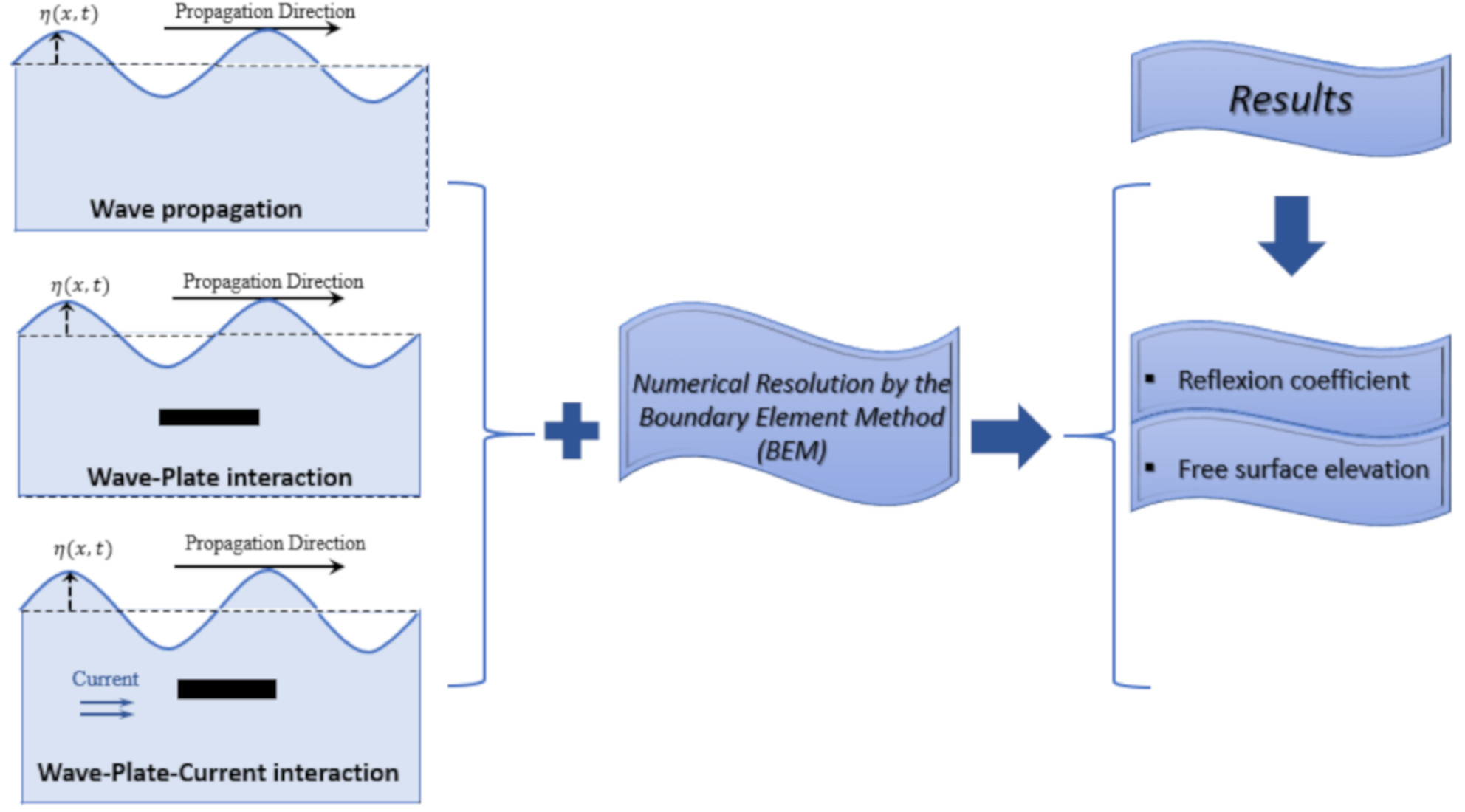
1. Introduction
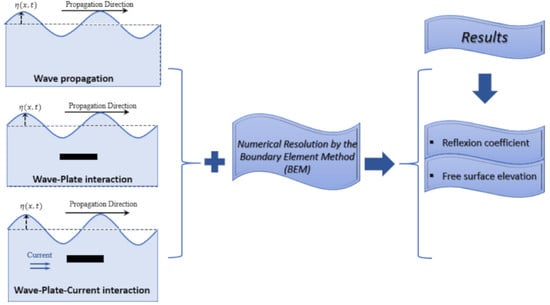
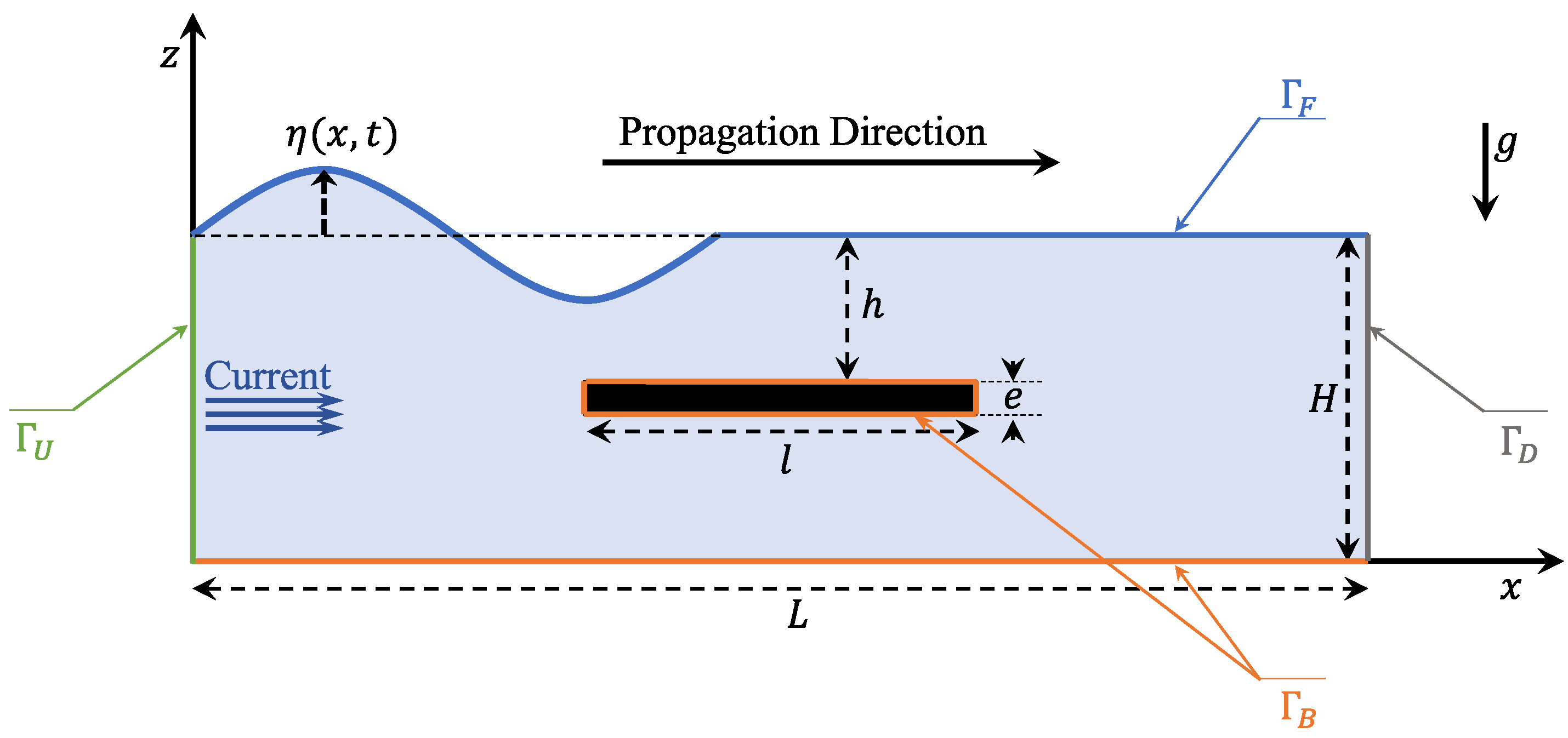
2. Materials and Methods
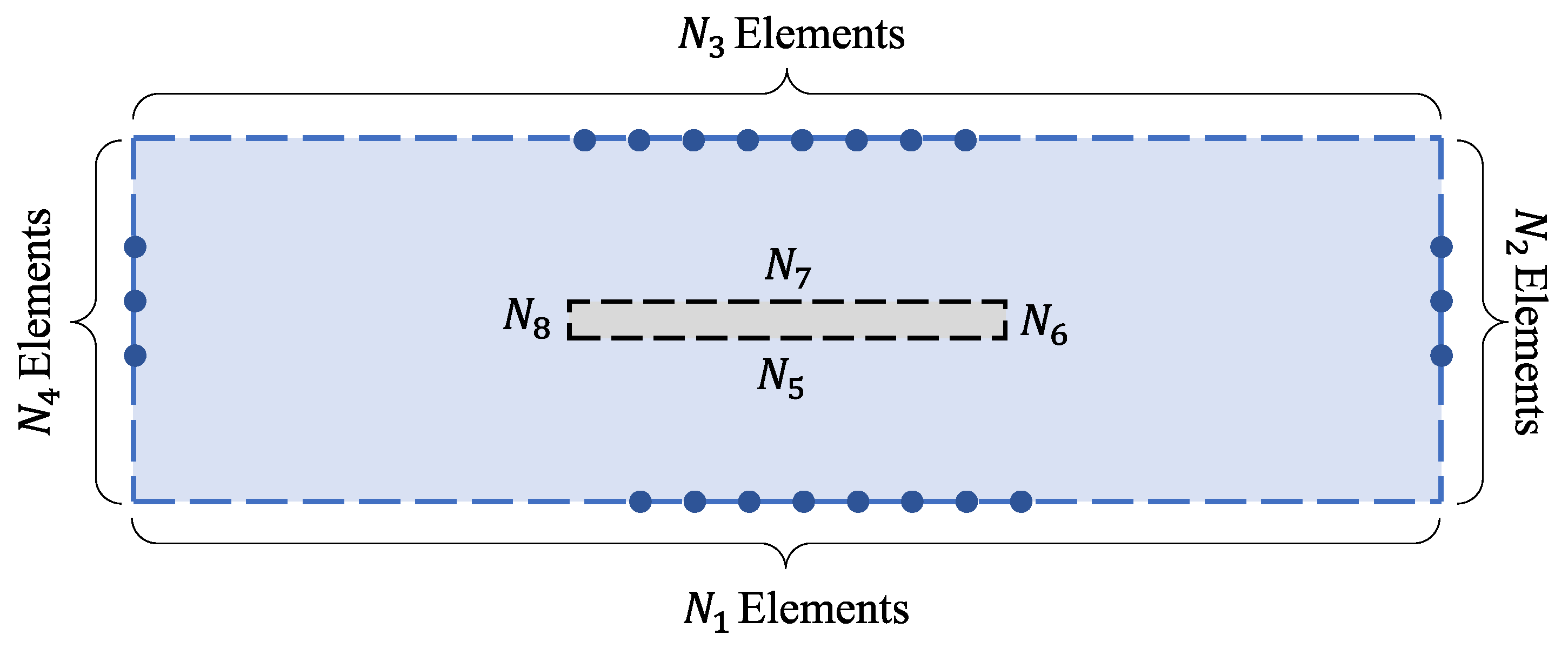
3. Numerical Formulation
- •
- For : and
- •
- For : and
4. Results and Discussions
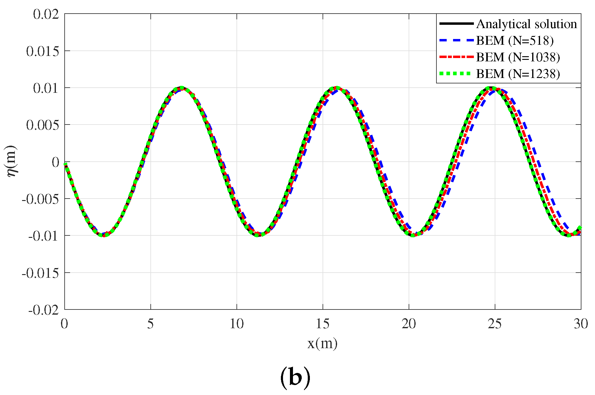
4.1. Validation of the Numerical Code: (Absence of the Current)
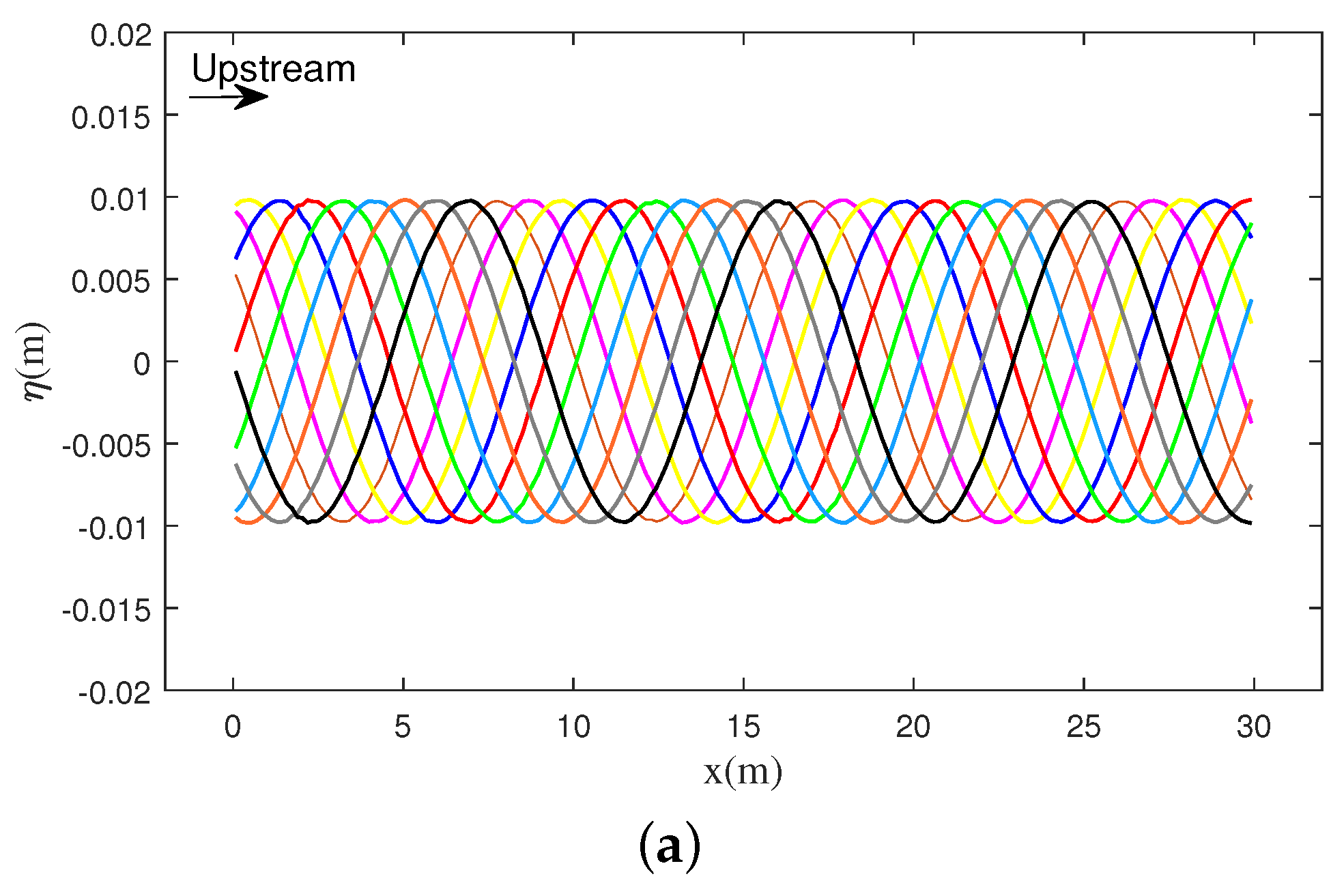
4.1.1. Case of Flat-Bottom
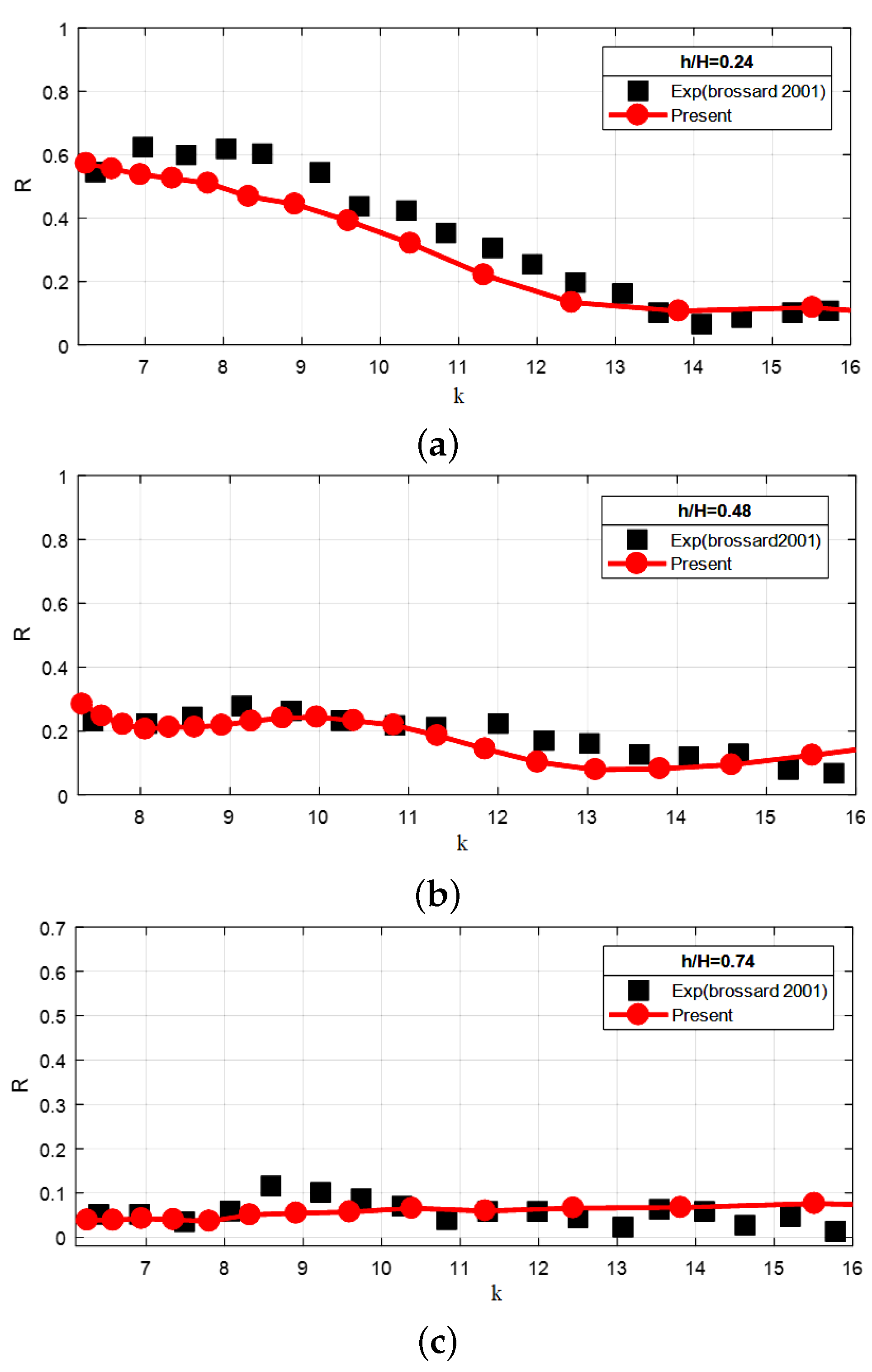
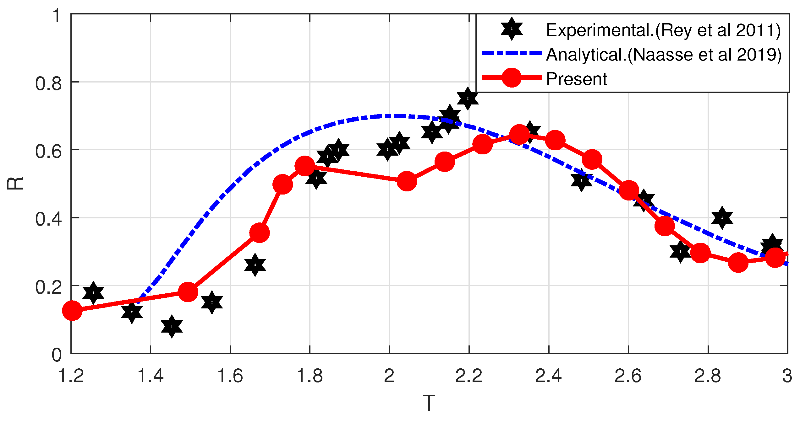
4.1.2. Case of Wave-Submerged Plate Interaction
4.2. Wave-Submerged Plate Interaction in the Presence of Current
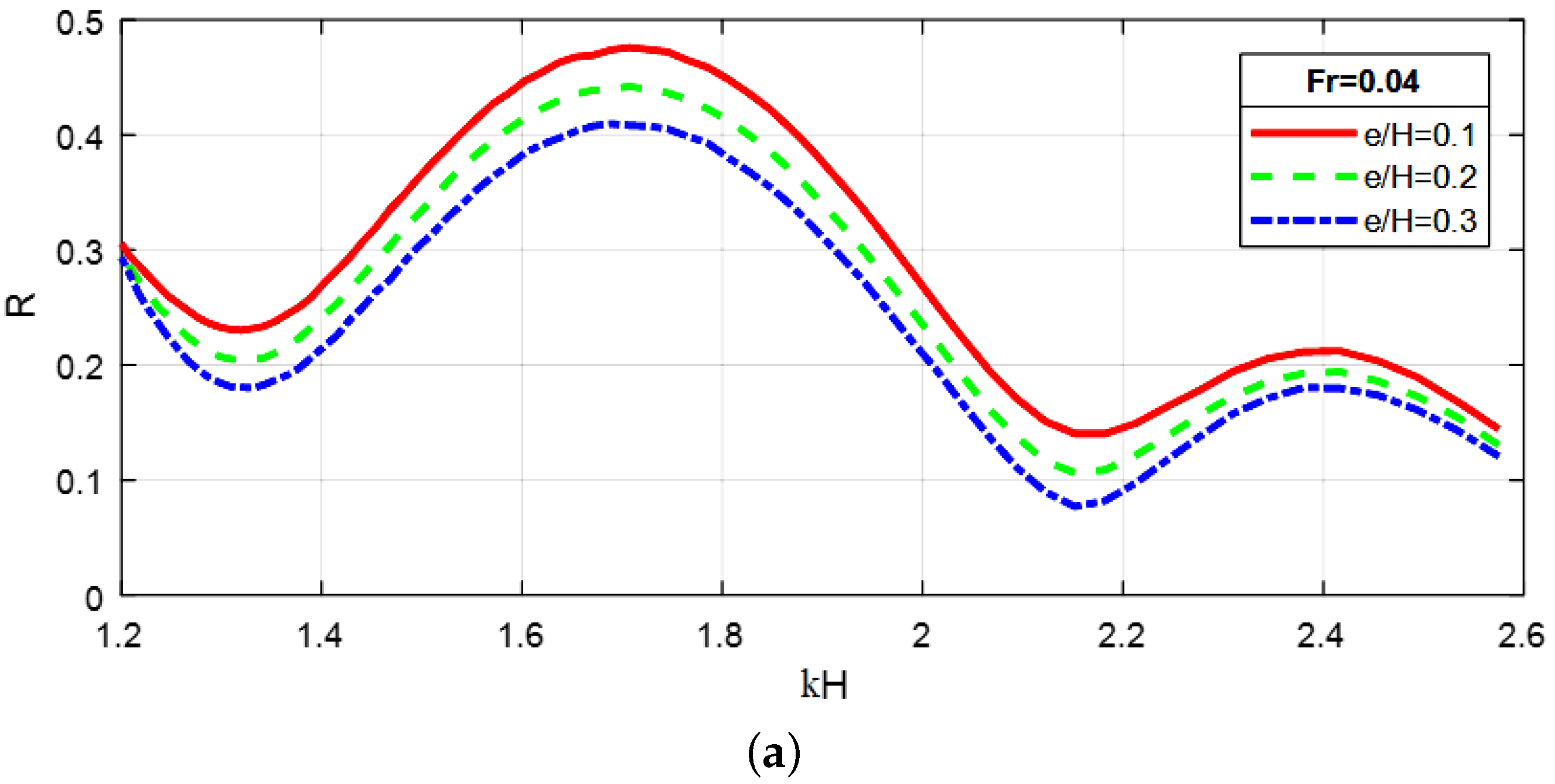
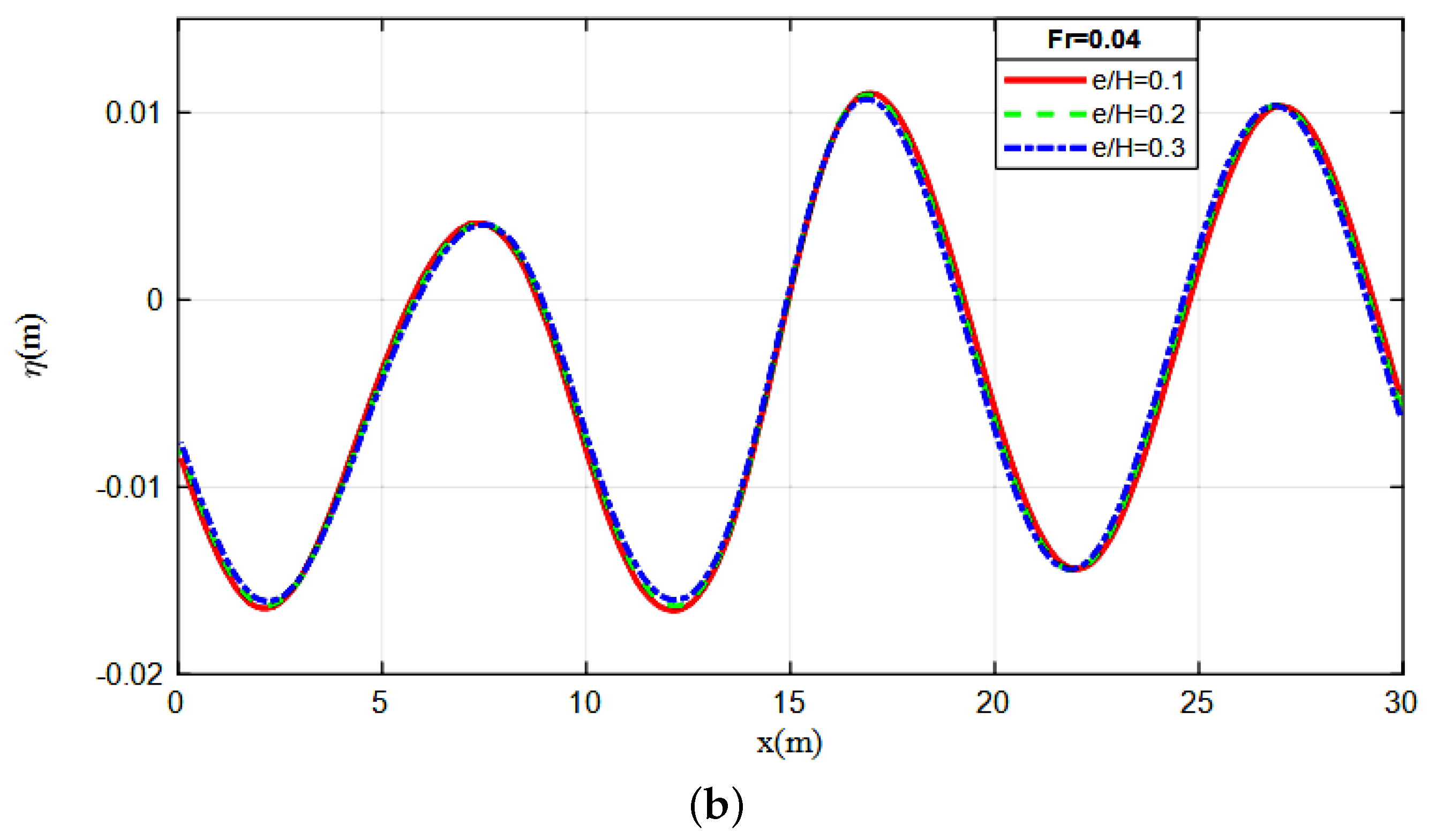
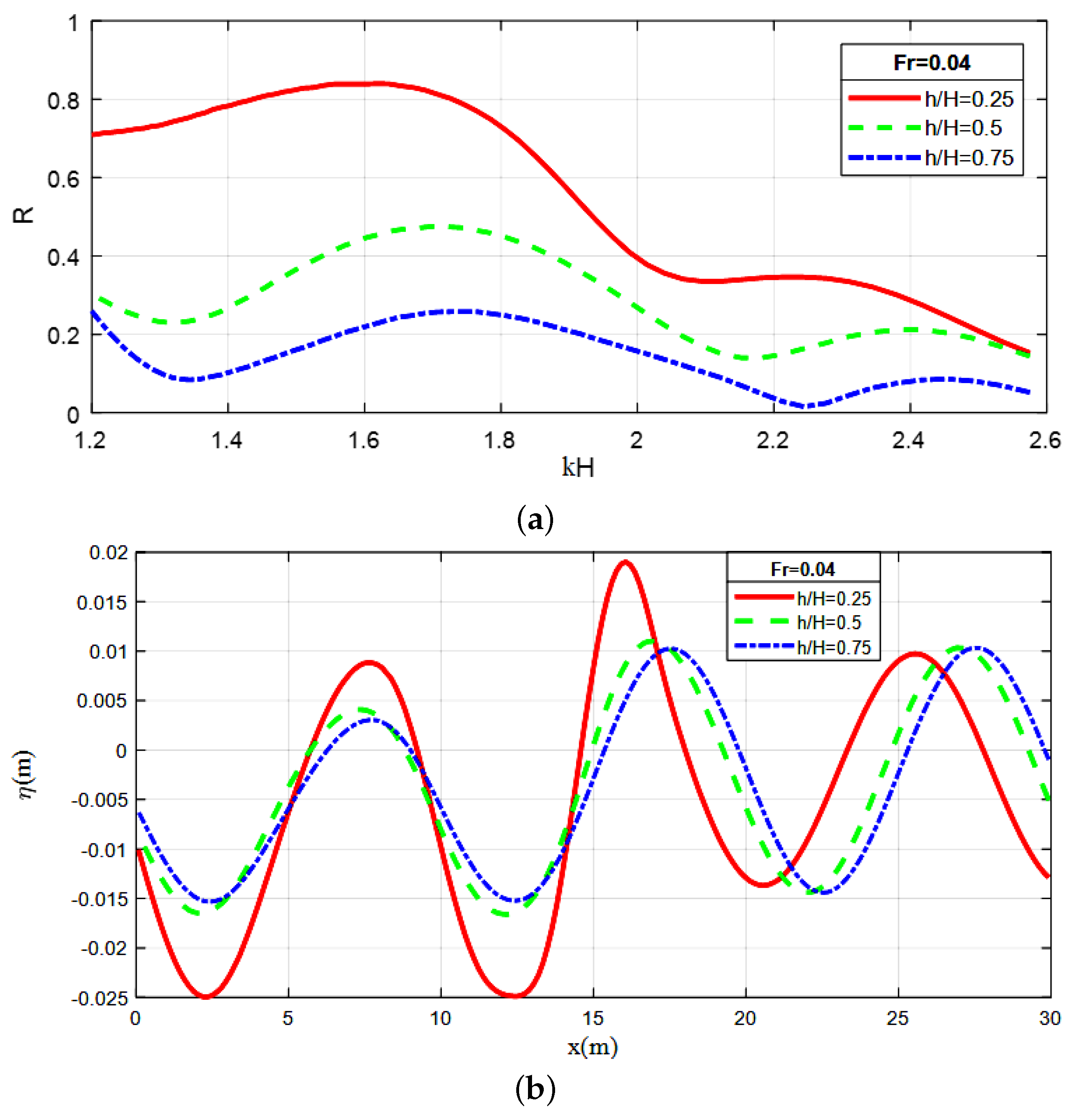
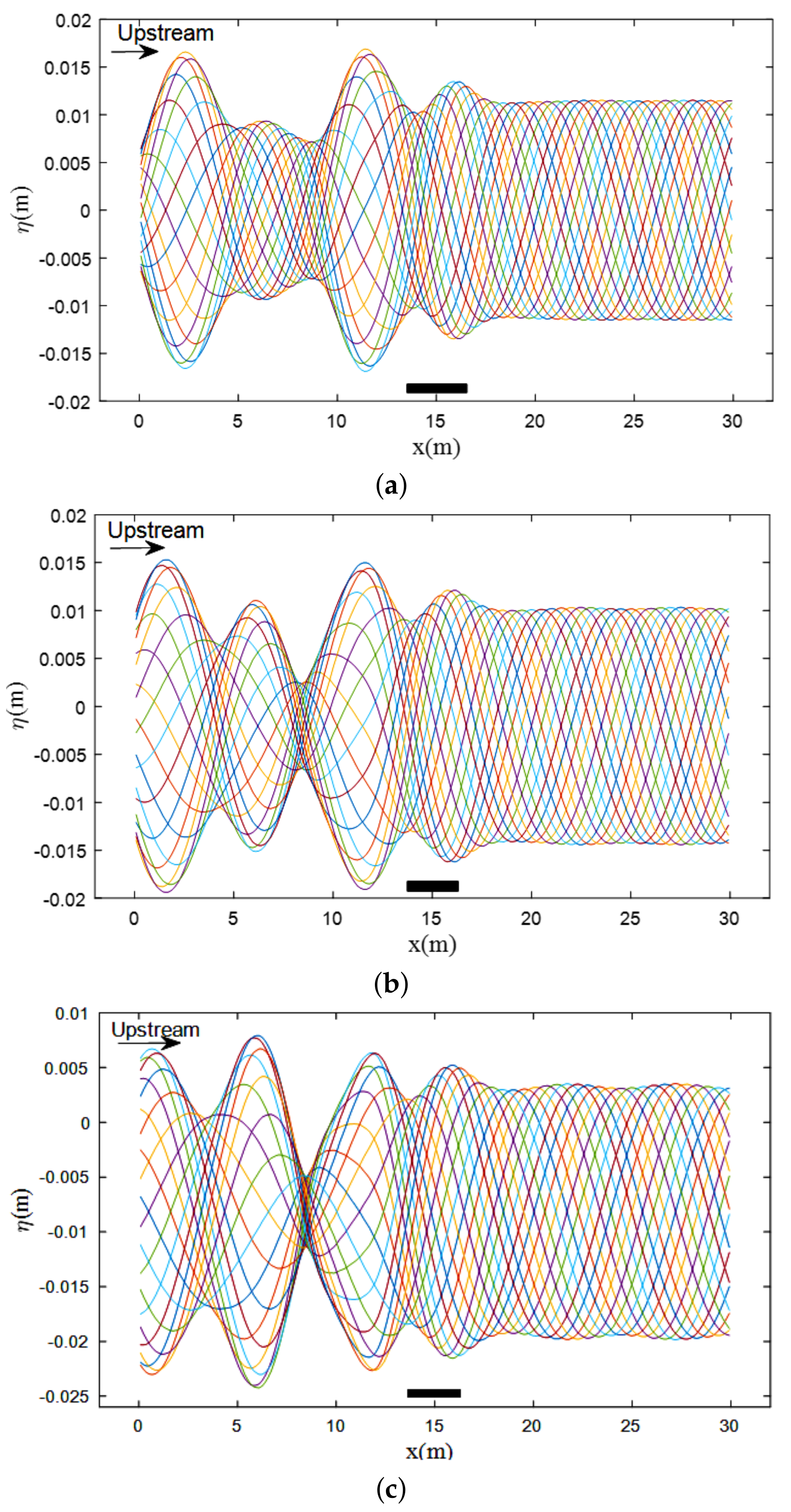
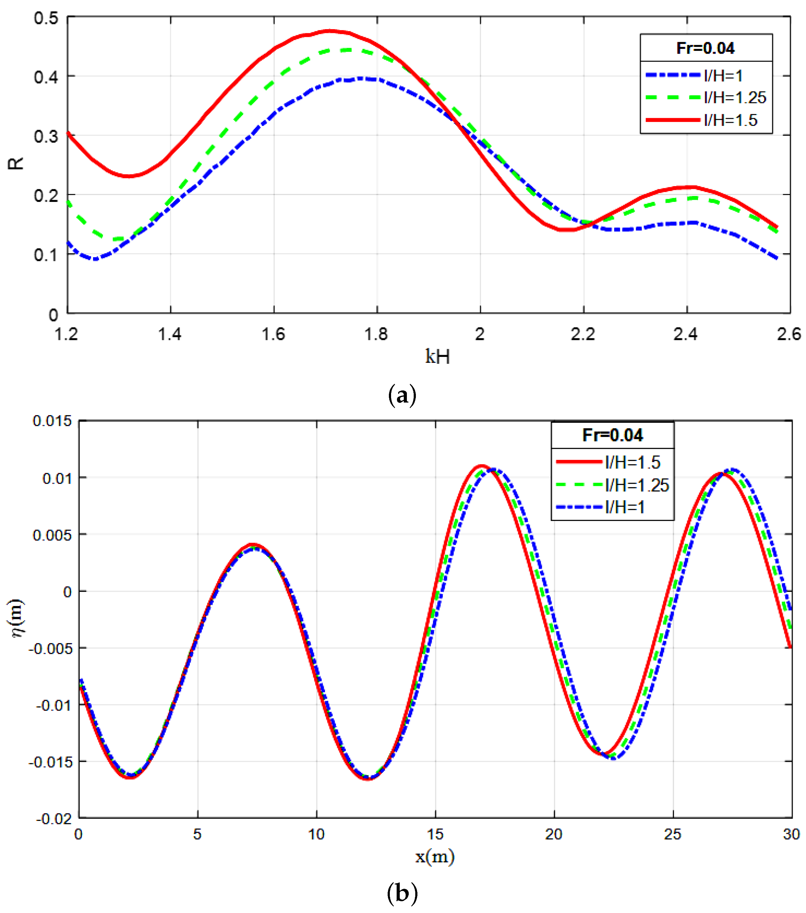
4.2.1. Effect of Geometric Parameters of the Plate
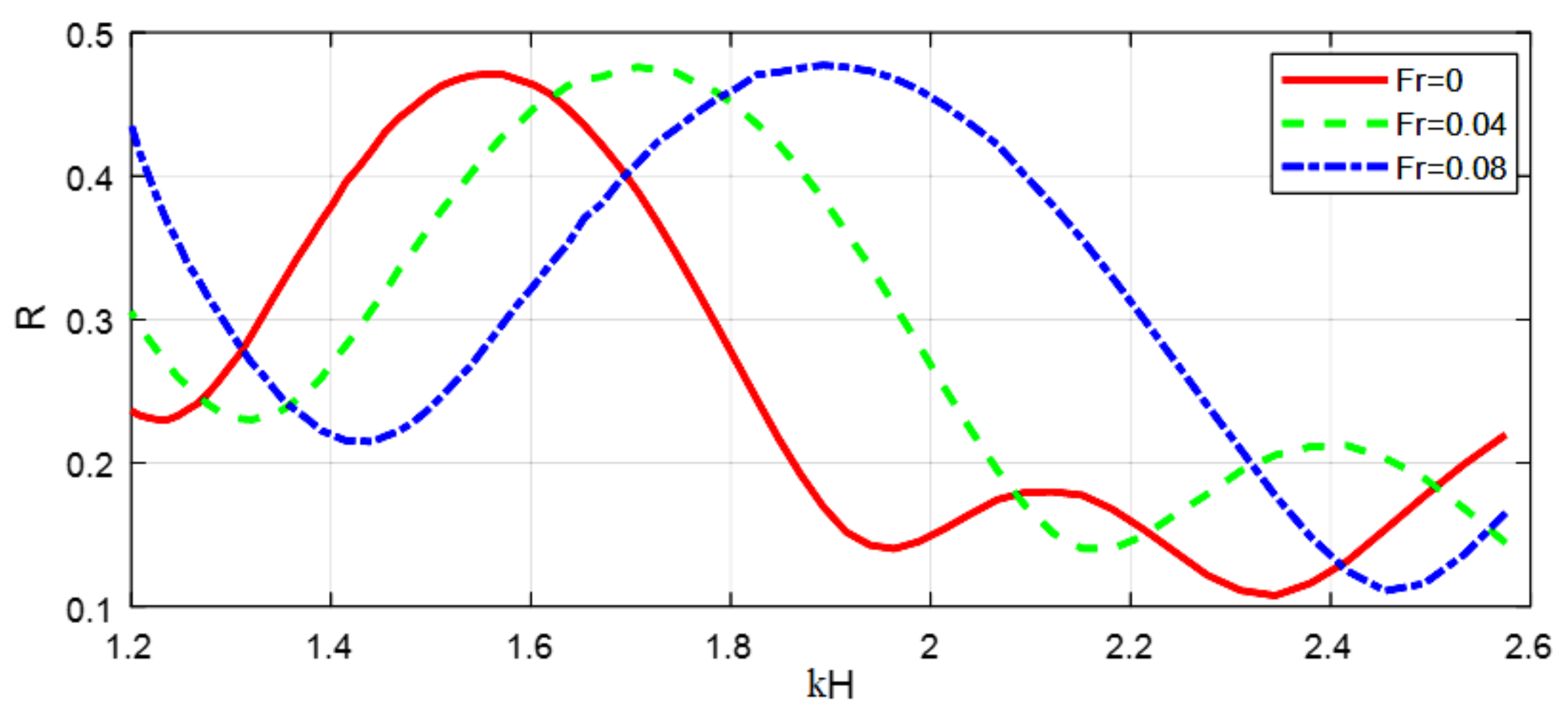
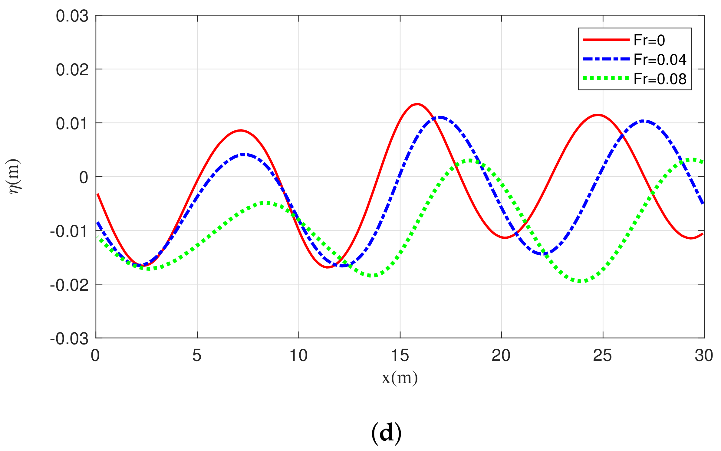
4.2.2. Effect of the Current
5. Conclusions
Author Contributions
Funding
Institutional Review Board Statement
Informed Consent Statement
Data Availability Statement
Conflicts of Interest
Abbreviations
| BEM | boundary element method |
| NWT | numerical wave tank |
References
- Brossard, J.; Chagdali, M. Experimental investigation of the harmonic generation by waves over a submerged plate. Coast. Eng. 2001, 42, 277–290. [Google Scholar] [CrossRef]
- Brossard, J.; Perret, G.; Blonce, L.; Diedhiou, A. Higher harmonics induced by a submerged horizontal plate and a submerged rectangular step in a wave flume. Coast. Eng. 2009, 56, 11–22. [Google Scholar] [CrossRef]
- Liu, C.; Huang, Z.; Tan, S. Nonlinear scattering of non-breaking waves by a submerged horizontal plate: Experiments and simulations. Ocean Eng. 2009, 36, 1332–1345. [Google Scholar] [CrossRef]
- Xie, Z.; Stoesser, T.; Yan, S.; Ma, Q.; Lin, P. A Cartesian cut-cell based multiphase flow model for large-eddy simulation of three-dimensional wave-structure interaction. Comput. Fluids 2020, 213, 104747. [Google Scholar] [CrossRef]
- El Aarabi, L.; Mouakkir, L.; Mordane, S. Numerical Modeling of the Wave-Structure Interaction Using the Boundary Element Method. Softw. Eng. Perspect. Intell. Syst. 2020, 1294, 292–303. [Google Scholar]
- Zou, Z.L.; Hu, P.C.; Fang, K.; Liu, Z. Boussinesq-type equations for wave-current interaction. Wave Motion 2013, 50, 655–675. [Google Scholar] [CrossRef]
- Ning, D.; Lin, H.; Teng, B.; Zou, Q. Higher harmonics induced by waves propagating over a submerged obstacle in the presence of uniform current. China Ocean Eng. 2014, 28, 725–738. [Google Scholar] [CrossRef]
- Ning, D.; Lin, H.; Teng, B.; Zou, Q. Study of interaction between wave-current and the horizontal cylinder located near the free surface. Appl. Ocean. Res. 2017, 67, 44–58. [Google Scholar]
- Lim, K.Y.; Madsen, O.S. An experimental study on near-orthogonal wave–current interaction over smooth and uniform fixed roughness beds. Coast. Eng. 2016, 116, 258–274. [Google Scholar] [CrossRef]
- Fan, C.M.; Chu, C.-N.; Sarler, B.; Li, T.H. Numerical solutions of waves-current interactions by generalized finite difference method. Eng. Anal. Bound. Elem. 2018, 100, 150–163. [Google Scholar] [CrossRef]
- Hsiao, Y.; Tsai, C.-L.; Chen, Y.-L.; Wu, H.-L.; Hsiao, S.-C. Simulation of wave-current interaction with a sinusoidal bottom using OpenFOAM. Appl. Ocean. Res. 2020, 94, 101998. [Google Scholar] [CrossRef]
- Rey, V.; Capobianco, R.; Dulou, C. Wave scattering by a submerged plate in presence of a steady uniform current. Coast. Eng. 2002, 47, 27–34. [Google Scholar] [CrossRef]
- Rey, V.; Touboul, J. Forces and moment on a horizontal plate due to regular and irregular waves in the presence of current. Appl. Ocean. Res. 2011, 33, 88–99. [Google Scholar] [CrossRef]
- Zhang, J.; Zhu, B.; Kang, A.; Yin, R.; Li, X.; Huang, B. Experimental and numerical investigation of wave-current forces on coastal bridge superstructures with box girders. Adv. Struct. Eng. 2020, 23, 1438–1453. [Google Scholar] [CrossRef]
- Ning, D.; Chen, L.; Lin, H.; Zou, Q.; Teng, B. Interaction mechanisms among waves, currents and a submerged plate. Appl. Ocean. Res. 2019, 91, 101911. [Google Scholar] [CrossRef]
- Errifaiy, M.; Naasse, S.; Chahine, C. Analytical determination of the reflection coefficient by the evanescent modes model during the wave-current-horizontal plate interaction. Comptes Rendus Mécanique 2016, 344, 479–486. [Google Scholar] [CrossRef]
- Naasse, S.; Errifaiy, M.; Chahine, C. Analytical study of the effect of the geometrical parameters during the interaction of regular wave-horizontal plate-current. Acta Oceanol. Sin. 2019, 38, 10–20. [Google Scholar] [CrossRef]
- Wrobel, L.C. The Boundary Element Method, Volume 1: Applications in Thermo-Fluids and Acoustics; John Wiley & Sons: Hoboken, NJ, USA, 2002. [Google Scholar]
- Lee, J.-J. Wave-induced oscillations in harbours of arbitrary geometry. J. Fluid Mech. 1971, 45, 375–394. [Google Scholar] [CrossRef]
- Dabsi, N. Modélisation Numérique des Oscillations Induites Dans un Port Sollicité par une Houle Incidente et Étude du Comportement d’un Navire Amarré; Université Hassan II, Faculté des Sciences Ben M’Sik: Casablanca, Morocco, 1998. [Google Scholar]
- Airy, G.B. Tides and Waves; B. Fellowes: London, UK, 1845. [Google Scholar]


Publisher’s Note: MDPI stays neutral with regard to jurisdictional claims in published maps and institutional affiliations. |
© 2021 by the authors. Licensee MDPI, Basel, Switzerland. This article is an open access article distributed under the terms and conditions of the Creative Commons Attribution (CC BY) license (https://creativecommons.org/licenses/by/4.0/).
Share and Cite
Akarni, H.; El Aarabi, L.; Mouakkir, L.; Mordane, S. Numerical Modeling of the Wave-Plate-Current Interaction by the Boundary Element Method. Fluids 2021, 6, 435. https://doi.org/10.3390/fluids6120435
Akarni H, El Aarabi L, Mouakkir L, Mordane S. Numerical Modeling of the Wave-Plate-Current Interaction by the Boundary Element Method. Fluids. 2021; 6(12):435. https://doi.org/10.3390/fluids6120435
Chicago/Turabian StyleAkarni, Hasna, Laila El Aarabi, Laila Mouakkir, and Soumia Mordane. 2021. "Numerical Modeling of the Wave-Plate-Current Interaction by the Boundary Element Method" Fluids 6, no. 12: 435. https://doi.org/10.3390/fluids6120435
APA StyleAkarni, H., El Aarabi, L., Mouakkir, L., & Mordane, S. (2021). Numerical Modeling of the Wave-Plate-Current Interaction by the Boundary Element Method. Fluids, 6(12), 435. https://doi.org/10.3390/fluids6120435