Abstract
An analytical model has been formulated to describe the generation of Hermite–Gaussian (HG) modes within Raman lasers through manipulation of the Stokes field’s optical axis deflection angle and its spatial offset relative to the pump field. This model predicts the dependence of HG modes’ oscillation on the angular deviation and off-axis distance between the optical axes of the pump and Stokes fields. Furthermore, an optical system has been engineered specifically for the generation of HG modes in a continuous-wave external cavity diamond Raman laser configuration. Experimental validation demonstrates strong concordance with theoretical predictions.
1. Introduction
The Stimulated Raman Scattering (SRS) effect is the third-order nonlinear effect of shifting the wavelength of conventional lasers to broaden the spectral range from deep ultraviolet to far infrared. Beyond wavelength versatility, SRS offers unique advantages, including automatic phase matching, cascaded output capability, and beam self-cleaning properties [1,2,3]. Raman lasers exhibit substantial applicability across multiple domains, including light detection and ranging (LIDAR) systems, laser guide stars for adaptive optics, atomic cooling experiments, and optical trapping technologies [4,5,6,7,8,9,10]. Compared to conventional population-inversion-based lasers, Raman lasers not only provide superior spectral flexibility but also facilitate single-longitudinal-mode operation due to the resonant enhancement in standing-wave cavities—a critical feature for applications such as optical trapping [11].
Over the past decade, the emergence of high-quality single-crystal chemical vapor deposition (CVD) diamond has revolutionized the design of crystalline Raman lasers. With its exceptional Raman shift, high Raman gain coefficient, and outstanding thermal properties, CVD diamond has become the predominant Raman gain medium in modern laser systems [12,13,14,15]. Diamond Raman lasers achieve high output power levels from ultraviolet to mid-infrared wavelength [16,17,18,19,20,21,22]. Consequently, diamond Raman lasers have attracted significant research attention.
Optimization of Raman laser resonators centers on sustaining high-power TEM00 mode operation. Empirical observations establish that the Raman gain of each transverse mode orders governs transverse mode competition dynamics and determines the Stokes threshold. In diamond Raman lasers, the Stokes gain as the function of transverse mode orders is predominantly determined by the intensity-weighted spatial overlap between the Stokes and pump fields within the crystal (also called effective area). The transverse Stokes mode that exhibits maximum effective area with the pump field will achieve optimal gain and consequently dominate the laser oscillation [23]. Previous research has generated HG mode outputs through adjusting of the effective areas between the pump and Stokes transverse modes [24,25,26,27]. However, there is little published research on mechanisms, as well as the theoretical model. Several studies have further explored the underlying mechanisms behind this phenomenon: Reference [23] derived a model describing the relationship between the off-axis displacement and Stokes threshold for each order transverse mode in the Raman laser by incorporating the ratio of the fundamental transverse mode Stokes threshold to that of higher-order HG modes [26] into the expression for the effective area between the Stokes and pump fields. However, it neglected the influence of the angular deviation between the pump and Stokes fields. While Reference [25] theoretically analyzed the influence of the angular deviation on the effective area for each transverse mode of Stokes, it did not consider the effect of the off-axis displacement between the pump and Stokes fields.
This study introduces a theoretical framework based on the external cavity Raman model [28], which quantitatively characterizes the joint effects of optical axis angular deviation and off-axis distance between pump and Stokes fields on both transverse mode formation and output Stokes power. The proposed model undergoes experimental validation through the design and construction of the external cavity diamond Raman laser.
2. Modeling
The seminal analytical model developed by Kitzler et al. in 2015 established the theoretical framework for characterizing power dynamics in continuous-wave external cavity Raman lasers [28]. However, this model incorporates a constraint through its assumption of perfect collinearity between the pump and Stokes propagation axes. This idealized configuration inherently neglects two critical geometric factors: (1) angular misalignment and (2) spatial offset between the pump and Stokes fields. In this study, an enhanced theoretical model that incorporates both angular and spatial non-collinearity effects is presented. This advancement facilitates more accurate modeling of practical diamond Raman laser systems where perfect alignment cannot be guaranteed.
Under paraxial approximation, the growth of the intracavity Stokes field and depletion of a single pass pump field are governed by the following two differential equations:
where the subscript P and S mean pump and Stokes fields, respectively, is intracavity intensity, represents the quantum defect of the inelastic Raman process, where is wavelengths, is the parasitic losses and is the Stokes gain coefficient.
In Reference [28], the pump beam is coincident with the z-axis (no angular deviation). The intensity distribution of TEM00 field is
Considering the Stokes beam has a TEMmn intensity profile, Equation (3) can be rewritten as
where and are the beam radius in the x- and y-directions of the pump and the Stokes, respectively.
To include the angular deviation and the distance between the Stokes and pump optical axis, a more detailed definition for Equation (4) is shown as
where , , and and represent the angular deviations between the optical axes of the Stokes and the pump in the x-and y-directions, respectively (as shown in Figure 1a). and , describing the distances between the optical axes of the Stokes and the pump in the x-and y-directions, are called off-axis distances (as represented in Figure 1b).
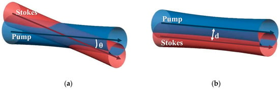
Figure 1.
Angular deviation and off-axis distance. (a) Angular deviation; (b) Off-axis distance.
In contrast to the formulation presented in Reference [28], this model incorporates both angular deviations () and off-axis distances () through the introduction of an effective area parameter. This parameter , defined as the inverse of the reciprocal overlap integral of the normalized fundamental and Stokes field profiles [29], is expressed as
Similar to Reference [28], in the case of double-pass pump, Equation (6) is combined and integrated to solve Equation (1):
where the variable α is passive losses of the Stokes in the cavity, T is the transmissivity of the output mirror to Stokes, L is the crystal length, is the pump power, is the Stokes output power, and is the gain coefficient describing the Raman gain in the focusing system [30]. , defined as the spatial integral of the reciprocal overlap of the normalized pump and Stokes intensity profiles, quantifies the degree of spatial mode overlap between the pump and Stokes intensity.
The proposed model enables quantitative prediction of Stokes thresholds for transverse modes of arbitrary orders (m, n), incorporating both angular deviations (, ) and off-axis distances (, ) as input parameters. In the cavity, the transverse mode with the lowest threshold power (which simultaneously exhibits the highest gain due to its maximal overlap with the gain structure) will oscillate first and dominate the output [26]. It should be noted that, in contrast to Reference [31]—which describes the generation of Ince–Gaussian (IG) modes in cylindrically symmetric resonators—the present model explicitly addresses the condition in which cylindrical symmetry is absent. Since non-cylindrically symmetric resonators are prevalent in most practical Raman laser cavities, including linear cavities with imperfect angular alignment, the proposed model remains general and applicable to a wide range of experimental configurations. Furthermore, in the absence of cylindrical symmetry, the tangential (T) and sagittal (S) planes become independent; consequently, angled HG modes do not participate in mode competition [32]. For this reason, the HG distribution considered in the model is restricted to the x- and y-directions.
3. The Experimental Setup
The experimental configuration of the external cavity diamond Raman laser is depicted in Figure 2. The pump beam was supplied by a narrow-linewidth Yb-doped fiber laser operating at 1064 nm, exhibiting a maximum continuous-wave output power of 80 W and a beam quality factor (M2) of 1.15. Subsequent to the pump source, two free-space optical isolators were employed to block back-reflection. The pump beam size was adjusted via a telescopic system (lenses L1 and L2) and a focusing lens (L3) to optimize mode matching with the Stokes beam within the diamond gain medium. Polarization alignment of the pump beam relative to the diamond’s <111> crystallographic orientation, requisite for maximizing Raman gain [33], was adjusted using a half-wave plate (HWP). The Raman resonator comprised two plano-concave mirrors (M1 and M2, possessing curvature radii of 50 mm and 75 mm, respectively). M1 featured coatings exhibiting high transmission (>91.3%) at the pump wavelength (1064 nm) and high reflectivity (99.95%) at the Stokes wavelength (1240 nm). M2 functioned as the Stokes output coupler (OC), with high-reflectivity coatings at both 1064 nm (99.9%) and 1240 nm (99.97%). The low-transmittance output coupler was selected to provide a high-Q cavity, which enabled stable output of all transverse mode patterns for reliable beam characterization. Both cavity mirrors were mounted on a 120 mm × 120 mm translation stage with a positioning accuracy of 0.01 mm, facilitating off-axis displacement of the Stokes field. To enable precise quantification of the off-axis distance, a 650 nm semiconductor reference laser was co-aligned and mounted on the translation stage. The position of this reference beam, captured externally by a beam analyzer (CCD2, DataRay, Monterey, CA, USA), was utilized to measure the off-axis displacement. The Raman medium was a 7 mm × 2 mm × 2 mm CVD diamond (Type IIa, Element Six), oriented for propagation along a <110> direction and featuring anti-reflection coatings (R < 0.2%) at both 1064 nm and 1240 nm. The crystal was positioned at the resonator focus within a water-cooled copper mount. The calculated Stokes beam waist radius within the diamond was 52 µm, with distances of 48 mm to M1 and 72.5 mm to M2. Following the Raman cavity, the output Stokes beam and residual pump radiation were collimated using a focusing lens (L4). Beam profile characterization was subsequently performed using a beam analyzer (CCD1, DataRay, Monterey, CA, USA) mounted on a 120 mm × 120 mm guide rail.
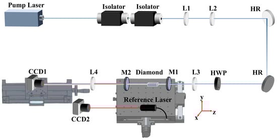
Figure 2.
Schematic diagram of the external cavity diamond Raman laser experimental setup. HR, high reflectivity mirror; HWP, half-wave plate; CCD1 and 2, beam analyzer; L1–L4, focusing lens.
4. Results and Discussion
This section presents the validation results of the theoretical model alongside corresponding numerical simulations. Due to the geometric symmetry of the linear cavity and the orthogonal alignment of its optical elements, the ABCD ray-transfer matrices remain identical in both the tangential and sagittal planes (T-S symmetry). Consequently, model validation was conducted exclusively along a single transverse direction without loss of generality, thereby optimizing experimental efficiency while maintaining theoretical rigor.
4.1. Angular Deviation
The angles of mirrors M1 and M2 were adjusted in the x-direction to vary , thereby generating high-order transverse Stokes modes (as shown in Figure 3). The threshold power for each HG mode was determined by gradually reducing the pump power until the beam spot captured on CCD1 transitioned from a stable, continuous pattern to an intermittent or flickering appearance, with the power at this transition point recorded as the corresponding mode threshold. Note that the observed TEM30 mode in Figure 3d existed in a regime of mode competition with the TEM20 mode. By documenting the spot size coordinates at opposing termini of the guide rail, was calculated through the ABCD matrix. The comparison between theoretical and experimental results at the same value is shown in Table 1. The observed discrepancies between experimental and theoretical results are primarily attributed to the spatially random birefringence distribution within the diamond crystal, which critically modulates the Raman gain [34]. According to the established thermal model for external-cavity diamond Raman lasers [35], the estimated thermal focal length in our system exceeds 28 m, an effect that can therefore be neglected in the present analysis. Regarding experimental uncertainties, the CCD, power meter, guide rail, and translation stage used in the measurements have specified accuracies of ±0.006 mm, ±1 W, ±0.05 mm, and ±0.01 mm, respectively. Furthermore, the angular deviation is subject to an uncertainty originating from the combined limits of CCD1 and the guide rail, which propagates through the ABCD transfer matrix to yield an angular error of ±0.01°. When these uncertainties are propagated through the model, the resulting predicted threshold variation remains about ±0.17 W. It is noteworthy that the predicted TEM20 mode at occurs near the TEM20-TEM30 boundary, consistent with the observed mode competition in Figure 3d.
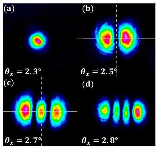
Figure 3.
The Stokes HG mode profile at different . (a) TEM00; (b) TEM10; (c) TEM20; (d) TEM30.

Table 1.
Measured and calculated Stokes thresholds and HG mode as a function of .
Figure 4 shows the Stokes threshold as the function of for TEM00 to TEM40. The squares marked with the labels are the measured data. For , the dominant mode is TEM00. As increases, especially when , the threshold differentials between transverse modes progressively diminish, and Stokes emission shifts to higher-order modes. The convergence of thresholds is caused by reduced differences in among modes, as shown in Figure 5. This results from shorter effective interaction lengths at larger , attenuating the impact of modal profile differences. Consequently, Raman gains become more uniform, intensifying mode competition—consistent with Reference [25].
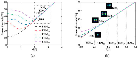
Figure 4.
Relationship between the Stokes threshold of the first five TEMm0 mode and ((b) is a magnified view of (a)). Among these data points, K00 to K30, respectively, show the measured Stokes threshold of TEM00 to TEM30 under the corresponding in Table 1.
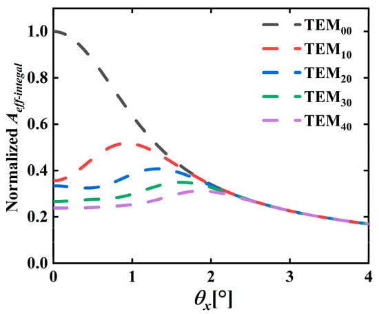
Figure 5.
Relationship between the of the first five TEMm0 mode and the pump mode under different in diamond.
The influence of and on the transverse mode with the minimum Stokes threshold is quantified in Figure 6. The parameter space exhibits a notable characteristic: the fundamental transverse mode (TEM00) dominates across most regions, irrespective of and variations. Higher-order modes (TEMm0 and TEM0n) emerge only under specific angular adjustments. Figure 6 reveals that at fixed , increasing elevates the order m of the TEMm0 mode with the minimum Stokes threshold, concurrently raising the Stokes threshold. Interestingly, when is not too small, the changes in will lead the TEM00 mode to hold the minimum threshold. For elevated values, transition boundaries shift toward higher (Figure 6b). T-S symmetry indicates analogous behavior in TEM0n-dominated regimes.
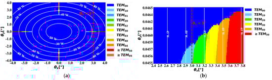
Figure 6.
Relationship between , and the minimum Stokes threshold modes of the first six orders ((b) is a magnified view of (a)). The white contour lines represent the changes in the minimum Stokes threshold, and the red dotted line corresponds to the position analyzed in Figure 7.
To elucidate the factors contributing to the predominant TEM00 mode, Figure 7 presents an analysis of variation between Stokes and pump fields for the first six transverse modes within the crystal as a function of , with (Corresponding to the red dotted line in Figure 6). The results demonstrate a progressive decrease in for all modes as increases. Furthermore, certain HG modes exhibit transient convergence in their under these conditions. Crucially, beyond a specific threshold, the of the TEM00 mode surpasses that of the TEM30 mode, thereby enabling TEM00 to dominate the oscillation process. This behavior originates from different pump-Stokes overlapping geometries under varying deflection conditions. When the Stokes field undergoes unidirectional angular deflection ( or ), higher-order transverse modes (TEMm0 or TEM0n) with one-dimensional intensity distributions demonstrate enhanced the effective overlap with the pump field due to their elongated mode profiles along the deflection axis. In contrast, angular deflection of and results in substantially degraded for two-dimensional higher-order modes (TEMmn, ), as their more dispersed intensity distributions exhibit inferior mode matching compared to TEM00.
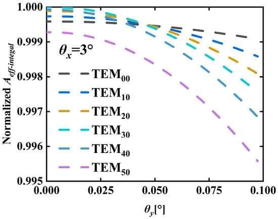
Figure 7.
Relationship between the of the first six TEMm0 modes and the pump mode within the diamond for different values when .
4.2. Off-Axis Distance
The Raman cavity mounting stage was adjusted to introduce off-axis displacement along the x-direction after optimizing M1 and M2 for minimal angular deviation (). Starting from the TEM20 mode—observed at the TEM20/TEM10 boundary and used as the reference where the model predicted —reversing the displacement direction enabled sequential mode transitions from TEM20 to TEM00 and eventually to the TEM10 mode on the opposite side. The changes in off-axis distance and Stokes threshold were recorded and compared with model predictions in Table 2, showing good agreement.
Table 2.
Measured and calculated Stokes thresholds and HG mode as a function of dx.
Figure 8 shows the relationship between off-axis displacement (normalized as ) and Stokes thresholds for the first five transverse modes. Increasing progressively shifts the dominant mode from TEM00 to higher orders while raising thresholds. In contrast to angular deviations, off-axis displacement induces no convergence of thresholds among different modes. This absence of threshold degeneracy facilitates stable oscillation of higher-order transverse modes under controlled displacement conditions.
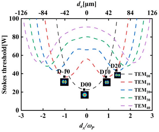
Figure 8.
Relationship between the Stokes threshold of the first five TEMm0 modes and . The data points D-10~D20 respectively represent the measured Stokes threshold of the corresponding modes in Table 2.
To better understand the impact of off-axis displacement on the Stokes threshold of transverse modes, we introduced the dimensionless ratio (with ) as a measure of the relative pump-Stokes beam waists. Figure 9 presents the Stokes threshold dependence on for the first five TEMm0 modes at discrete values. Under small pump waists (), the Stokes thresholds of different transverse modes exhibit pronounced fluctuations with , arising from the property of Hermite polynomials [26] and the consequent variations in the . Conversely, expanded pump waists () significantly suppress these threshold oscillations. This stabilization occurs because the becomes progressively insensitive to intensity profile variations as increases.
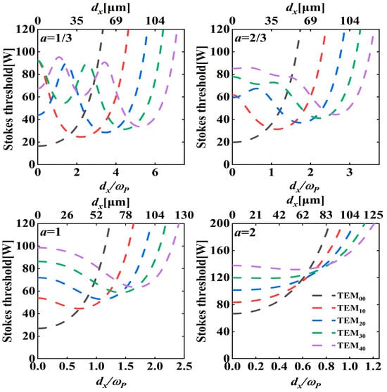
Figure 9.
Relationship between the Stokes threshold of the first five TEMm0 modes and under different value.
To address the two-dimensional off-axis configuration, Figure 10 illustrates the dependence of dominant transverse modes on and . Note that the black contour lines mean the minimum Stokes threshold. Due to limitations of the computational cost, analysis is restricted to transverse modes of order . Therefore, all higher-order transverse modes are subsumed within the 5th-order transverse mode, collectively denoted as “≥TEM50”. Owing to the T-S symmetry, Figure 10 demonstrates symmetric threshold and mode distributions, where increasing and elevates the mode orders n and m, respectively, accompanied by higher Stokes thresholds. In contrast to Reference [36], our results show that two-dimensional HG modes emerge under two-dimensional off-axis conditions, as opposed to one-dimensional modes, due to the broken cylindrical symmetry in our model assumption.
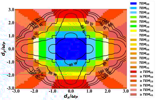
Figure 10.
Relationship between , and the minimum Stokes threshold mode of the first five orders. The black contour lines represent the changes in the minimum Stokes threshold.
In order to study the composite effects caused by off-axis distance and angular deviation, Figure 11 demonstrates the relationship between , and the lowest Stokes threshold modes of the first five orders. Similar to Figure 6, larger angular deflection expands TEM00 dominance while shrinking higher-order regions, showing that mode control via off-axis displacement requires minimal angular deviation, while increasing can recover TEM00 operation from higher-order modes with higher Stokes thresholds. Thus, optimal power output requires fundamental mode operation at minimal threshold, necessitating threshold monitoring.
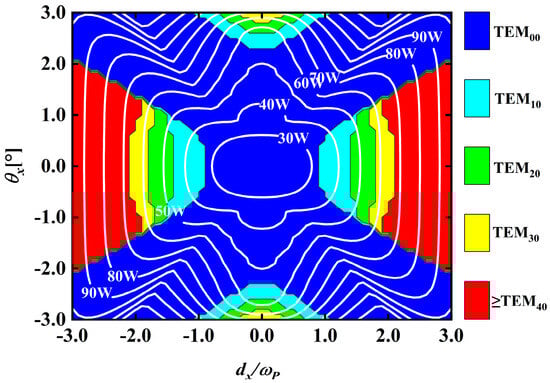
Figure 11.
Relationship between , and the lowest Stokes threshold modes of the first five orders. The white contour lines represent the changes in the minimum Stokes threshold.
5. Conclusions
This study presents an analytical model for generating high-order Hermite–Gaussian (HG) modes in external-cavity diamond Raman lasers through controlled off-axis displacement and angular deviations. The experimental results show that the model can predict the Raman laser threshold close to the measured value according to the input angular deviation and off-axis distance and infer the HG mode with the minimum Stokes threshold. It should be noted that the model presented assumes that the thermal lens induced in the diamond does not significantly change the pump and Stokes waist sizes; consequently, the T-S cavity symmetry is preserved. This symmetry may be broken under high-power operation or in the presence of significant thermal effects.
The model quantitatively describes how angular deviations and off-axis displacements affect Stokes thresholds and the lowest-threshold transverse mode. Large angular deviations cause threshold convergence to TEM00 with strong mode competition due to reduced effective interaction length, while off-axis displacements allow flexible HG mode generation via x-y displacement combinations. Notably, the Stokes threshold exhibits pronounced fluctuations with when , whereas a larger suppresses threshold variations and restricts the dominant mode range. Importantly, reverting to TEM00 does not guarantee optimal low-threshold operation, necessitating threshold evaluation. It should be noted that the model does not account for the cylindrical symmetry of involved fields. According to Reference [32], a two-dimensional off-axis displacement that preserves cylindrical symmetry can only generate one-dimensional transverse modes rotated by the corresponding angle in a cylindrically symmetric cavity. In contrast, the generation of the two-dimensional transverse modes illustrated in Figure 10 relies on the absence of cylindrical symmetry in the system. In order to verify the basic principle of the model, the cavity design with extremely high Q value is adopted in this study. The model itself does not limit the output coupling rate, and its theoretical framework is fully applicable to the case of higher transmission rate. Future work will focus on further verifying the power prediction ability of the model under the typical parameters of optimized power output (such as T = 1–10%) and applying it to the optimal design of laser efficiency.
The model provides a systematic approach for generating high-order HG modes in solid-state Raman lasers via angular and spatial control. These HG modes hold promising applications in fields such as precision measurement [37] and coherent communication [38,39]. Moreover, they offer a pathway to vortex beam generation, enabling high-power, narrow-linewidth vortex emission with the wavelength versatility in diamond Raman lasers [23,25,40]. Furthermore, the framework supports quantitative analysis of pump–Stokes power relationships across transverse modes and extends to cascaded Stokes fields, enabling systematic study of how spatial offsets affect output mode structures in cascaded Stokes systems.
Author Contributions
Conceptualization, Z.Z. and M.L.; methodology, Z.Z.; software, Z.Z.; validation, Z.Z.; formal analysis, Z.Z.; investigation, Z.Z. and M.L.; data curation, Z.Z.; writing—original draft preparation, Z.Z.; writing—review and editing, X.Y., Z.Z., and M.L.; supervision, X.Y., Y.F., W.C., D.C. and Y.S. All authors have read and agreed to the published version of the manuscript.
Funding
This research was funded by National Natural Science Foundation of China (12473080, U25A20509, 62505058), National Key Research and Development Program of China (2024YFE0206000, 2024YFB3613800).
Data Availability Statement
The data that support the findings of this study are available from the corresponding author upon reasonable request.
Conflicts of Interest
The authors declare no conflicts of interest.
References
- Penzkofer, A.; Laubereau, A.; Kaiser, W. High Intensity Raman Interactions. Prog. Quantum Electron. 1979, 6, 55–140. [Google Scholar] [CrossRef]
- Murray, J.T.; Austin, W.L.; Powell, R.C. Intracavity Raman Conversion and Raman Beam Cleanup. Opt. Mater. 1999, 11, 353–371. [Google Scholar] [CrossRef]
- Feng, Y. (Ed.) Raman Fiber Lasers; Springer Series in Optical Sciences; Springer International Publishing: Cham, Switzerland, 2017; Volume 207. [Google Scholar]
- Lux, O.; Sarang, S.; Williams, R.J.; McKay, A.; Mildren, R.P. Single Longitudinal Mode Diamond Raman Laser in the Eye-Safe Spectral Region for Water Vapor Detection. Opt. Express 2016, 24, 27812–27820. [Google Scholar] [CrossRef]
- Carlson, C.G.; Dragic, P.D.; Kirk Price, R.; Coleman, J.J.; Swenson, G.R. A Narrow-Linewidth, Yb Fiber-Amplifier-Based Upper Atmospheric Doppler Temperature Lidar. IEEE J. Sel. Top. Quantum Electron. 2009, 15, 451–461. [Google Scholar] [CrossRef]
- Yang, X.; Kitzler, O.; Spence, D.J.; Bai, Z.; Feng, Y.; Mildren, R.P. Diamond Sodium Guide Star Laser. Opt. Lett. 2020, 45, 1898–1901. [Google Scholar] [CrossRef]
- Wineland, D.J.; Itano, W.M. Laser Cooling of Atoms. Phys. Rev. A 1979, 20, 1521–1540. [Google Scholar] [CrossRef]
- Yamamoto, R.; Kobayashi, J.; Kuno, T.; Kato, K.; Takahashi, Y. An Ytterbium Quantum Gas Microscope with Narrow-Line Laser Cooling. New J. Phys. 2016, 18, 023016. [Google Scholar] [CrossRef]
- Curtis, J.E.; Koss, B.A.; Grier, D.G. Dynamic Holographic Optical Tweezers. Opt. Commun. 2002, 207, 169–175. [Google Scholar] [CrossRef]
- Nishigata, Y.; Lee, C.Y.; Miyamoto, Y.; Miyamoto, K.; Chen, Y.-F.; Omatsu, T. Optical Vortex Pumped Solid-State Raman Laser: Solid State Lasers XXVI: Technology and Devices 2017. In Solid State Lasers XXVI; SPIE: Bellingham, WA, USA, 2017. [Google Scholar] [CrossRef]
- Lux, O.; Sarang, S.; Kitzler, O.; Spence, D.J.; Mildren, R.P. Intrinsically Stable High-Power Single Longitudinal Mode Laser Using Spatial Hole Burning Free Gain. Optica 2016, 3, 876–881. [Google Scholar] [CrossRef]
- Mildren, R.P. Intrinsic Optical Properties of Diamond. In Optical Engineering of Diamond; Mildren, R.P., Rabeau, J.R., Eds.; Wiley: Hoboken, NJ, USA, 2013; pp. 1–34. [Google Scholar]
- Friel, I.; Geoghegan, S.L.; Twitchen, D.J.; Scarsbrook, G.A. Development of High Quality Single Crystal Diamond for Novel Laser Applications. In Proceedings of the Optics and Photonics for Counterterrorism and Crime Fighting VI and Optical Materials in Defence Systems Technology VII, Toulouse, France, 20–23 September 2010; Lewis, C., Burgess, D., Zamboni, R., Kajzar, F., Heckman, E.M., Eds.; SPIE: Bellingham, WA, USA, 2010; p. 783819. [Google Scholar]
- Chang, X.; Gao, W.; An, J.; Chen, H.; Liu, Z.; Qi, Z.; Li, C.; Ding, J.; Li, W.; Wang, K.; et al. Optical-Grade Diamond: Characteristics, Synthesis, and Recent Research Progress. Funct. Diam. 2025, 5, 2476690. [Google Scholar] [CrossRef]
- Functional Diamond Editors. Diamond Research: Highlights from 2023. Funct. Diam. 2024, 4, 2374566. [Google Scholar] [CrossRef]
- Granados, E.; Spence, D.J.; Mildren, R.P. Deep Ultraviolet Diamond Raman Laser. Opt Express 2011, 19, 10857–10863. [Google Scholar] [CrossRef]
- Mildren, R.P.; Butler, J.E.; Rabeau, J.R. CVD-Diamond External Cavity Raman Laser at 573 nm. Opt. Express 2008, 16, 18950–18955. [Google Scholar] [CrossRef]
- Bai, Z.; Williams, R.J.; Kitzler, O.; Sarang, S.; Spence, D.J.; Mildren, R.P. 302 W Quasi-Continuous Cascaded Diamond Raman Laser at 1.5 Microns with Large Brightness Enhancement. Opt. Express 2018, 26, 19797–19803. [Google Scholar] [CrossRef]
- Sabella, A.; Piper, J.A.; Mildren, R.P. Diamond Raman Laser with Continuously Tunable Output from 3.38 to 3.80 Μm. Opt. Lett. 2014, 39, 4037–4040. [Google Scholar] [CrossRef]
- Antipov, S.; Sabella, A.; Williams, R.J.; Kitzler, O.; Spence, D.J.; Mildren, R.P. 12 kW Quasi-Steady-State Diamond Raman Laser Pumped by an M2 = 15 Beam. Opt. Lett. 2019, 44, 2506. [Google Scholar] [CrossRef]
- Chen, H.; Cui, Y.; Li, X.; Zhang, B.; Cai, Y.; Ding, J.; Qi, Y.; Yan, B.; Wang, Y.; Lu, Z.; et al. High-Power Dual-Wavelength Intracavity Diamond Raman Laser. Funct. Diam. 2023, 3, 2282527. [Google Scholar] [CrossRef]
- Tan, W.; Wang, Y.; Chen, P.; Chen, R.; Zhu, S.; Yin, H.; Li, Z.; Chen, Z.; Dai, S. High Average Power Nanosecond Pulsed Single Longitudinal Mode Diamond Raman Laser in the 1.6 Μm Waveband. Funct. Diam. 2024, 4, 2423623. [Google Scholar] [CrossRef]
- Lee, C.-Y.; Chang, C.-C.; Cho, C.-Y.; Tuan, P.-H.; Chen, Y.-F. Generation of Higher Order Vortex Beams From a YVO4/Nd:YVO4 Self-Raman Laser via Off-Axis Pumping With Mode Converter. IEEE J. Select. Top. Quantum Electron. 2015, 21, 318–322. [Google Scholar] [CrossRef]
- An, J.; Bai, Z.; Zhu, Z.; Wang, Y.; Lu, Z. Experimental Demonstration of Intracavity Multiaxial Geometric Mode Structure Manipulation. Appl. Phys. Lett. 2024, 124, 061103. [Google Scholar] [CrossRef]
- Chen, H.; Bai, Z.; Chen, J.; Li, X.; Zhu, Z.-H.; Wang, Y.; Omatsu, T.; Mildren, R.P.; Lu, Z. Diamond Raman Vortex Lasers. ACS Photonics 2024, 12, 864–869. [Google Scholar] [CrossRef]
- Chen, Y.F.; Huang, T.M.; Kao, C.F.; Wang, C.L.; Wang, S.C. Generation of Hermite-Gaussian Modes in Fiber-Coupled Laser-Diode End-Pumped Lasers. IEEE J. Quantum Electron. 1997, 33, 1025–1031. [Google Scholar] [CrossRef]
- Xuan, C.; Zhou, Y.; Yang, X.; Ma, Y.; Rao, A.S.; Omatsu, T.; Bai, Z.; Wan, Y.; Wen, J.; Yusufu, T. Generation of High-Order Laguerre-Gaussian Modes from an Optical Vortex Pumped Diamond Raman Laser. Laser Photonics Rev. 2024, 18, 2400081. [Google Scholar] [CrossRef]
- Kitzler, O.; McKay, A.; Spence, D.J.; Mildren, R.P. Modelling and Optimization of Continuous-Wave External Cavity Raman Lasers. Opt. Express 2015, 23, 8590–8602. [Google Scholar] [CrossRef]
- Spence, D.J. Spatial and Spectral Effects in Continuous-Wave Intracavity Raman Lasers. IEEE J. Select. Top. Quantum Electron. 2015, 21, 134–141. [Google Scholar] [CrossRef]
- Boyd, G.; Johnston, W.; Kaminow, I. Optimization of the Stimulated Raman Scattering Threshold. IEEE J. Quantum Electron. 1969, 5, 203–206. [Google Scholar] [CrossRef]
- Liu, T.; Sheng, Q.; Geng, J.; Zhan, D.; Fu, S.; Zhu, Z.; Shi, W.; Yao, J. Oscillating Mode Analyzation of Off-Axis Pumped Laser via Fox-Li Method. Acta Opt. Sin. 2025, 46, 0414001. [Google Scholar] [CrossRef]
- Sheng, Q.; Zhan, D.; Geng, J.; Liu, T.; Shi, C.; Fu, S.; Shi, W.; Yao, J. Very-High-Order Two-Dimensional Hermite—Gaussian Mode Laser Based on Off-Axis Pumping and Astigmatic Cavity. Chin. J. Laser 2025, 52, 1015001. [Google Scholar] [CrossRef]
- Sabella, A.; Piper, J.A.; Mildren, R.P. 1240 nm Diamond Raman Laser Operating near the Quantum Limit. Opt. Lett. 2010, 35, 3874–3876. [Google Scholar] [CrossRef]
- Kitzler, O.; Spence, D.J.; Mildren, R.P. Generalised Theory of Polarisation Modes for Resonators Containing Birefringence and Anisotropic Gain. Opt. Express 2019, 27, 17209–17220. [Google Scholar] [CrossRef]
- Ding, J.; Li, Y.; Chen, H.; Cai, Y.; Bai, Z.; Qi, Y.; Yan, B.; Wang, Y.; Lu, Z. Thermal Modeling of an External Cavity Diamond Raman Laser. Opt. Laser Technol. 2022, 156, 108578. [Google Scholar] [CrossRef]
- Shen, Y.; Meng, Y.; Fu, X.; Gong, M. Wavelength-Tunable Hermite–Gaussian Modes and an Orbital-Angular-Momentum-Tunable Vortex Beam in a Dual-off-Axis Pumped Yb:CALGO Laser. Opt. Lett. 2018, 43, 291–294. [Google Scholar] [CrossRef] [PubMed]
- Du, J.; Li, W.; Wen, R.; Li, G.; Zhang, P.; Zhang, T. Precision Measurement of Single Atoms Strongly Coupled to the Higher-Order Transverse Modes of a High-Finesse Optical Cavity. Appl. Phys. Lett. 2013, 103, 083117. [Google Scholar] [CrossRef]
- Ndagano, B.; Mphuthi, N.; Milione, G.; Forbes, A. Comparing Mode-Crosstalk and Mode-Dependent Loss of Laterally Displaced Orbital Angular Momentum and Hermite–Gaussian Modes for Free-Space Optical Communication. Opt. Lett. 2017, 42, 4175–4178. [Google Scholar] [CrossRef]
- Pang, K.; Song, H.; Zhao, Z.; Zhang, R.; Song, H.; Xie, G.; Li, L.; Liu, C.; Du, J.; Molisch, A.F.; et al. 400-Gbit/s QPSK Free-Space Optical Communication Link Based on Four-Fold Multiplexing of Hermite–Gaussian or Laguerre–Gaussian Modes by Varying Both Modal Indices. Opt. Lett. 2018, 43, 3889–3892. [Google Scholar] [CrossRef]
- Ohtomo, T.; Chu, S.-C.; Otsuka, K. Generation of Vortex Beams from Lasers with Controlled Hermite- and Ince-Gaussian Modes. Opt. Express 2008, 16, 5082–5094. [Google Scholar] [CrossRef]


Disclaimer/Publisher’s Note: The statements, opinions and data contained in all publications are solely those of the individual author(s) and contributor(s) and not of MDPI and/or the editor(s). MDPI and/or the editor(s) disclaim responsibility for any injury to people or property resulting from any ideas, methods, instructions or products referred to in the content. |
© 2026 by the authors. Licensee MDPI, Basel, Switzerland. This article is an open access article distributed under the terms and conditions of the Creative Commons Attribution (CC BY) license.